Corbin Russwin PED5000 Series PED5200(A)(HC)(M107) Wide Stile Rim All Standard Trim Installation Instructions_FM577
Open the original PDF document
View PDFInstallation Instructions

PED5200 Series - Standard, Fire Rated, & Windstorm Rated
Rim Exit Devices With All Standard Trim

This product can expose you to lead which is known to the state of California to cause cancer and birth defects or other reproductive harm. For more information go to www. P65warnings.ca.gov.
WARNING
Attention Installer: Improper installation may result in damage to the product and void the factory warranty.
For installation assistance contact Corbin Russwin
1-800-543-3658 • techsupport.corbinrusswin@assaabloy.com
Copyright © 2023, ASSA ABLOY Access and Egress Hardware Group, Inc. All rights reserved. Reproduction in whole or in part without the express written permission of ASSA ABLOY Access and Egress Hardware Group, Inc. is prohibited. FM577 1/23
Rim Exit Devices With All Standard Trim
Installation Instructions

Screw Chart
| SCREW |
TOTAL QTY
SUPPLIED |
WHERE USED |
|---|---|---|
|
#10-24 X 3/4" FLAT HEAD
MACHINE SCREW |
4 |
(4) CHASSIS
CORNER MOUNTING HOLES (METAL DOOR) |
|
#10 X 1-1/4" FLAT HEAD
WOOD SCREW |
4 |
(4) CHASSIS
CORNER MOUNTING HOLES (WOOD DOOR) |
|
1/4"-20 X 5/8" FLAT HEAD
MACHINE SCREW |
2 |
(2) CHASSIS
INNER MOUNTING HOLES (METAL DOOR, FIRE RATED) |
|
#10-24 X 3/4" ROUND HEAD
MACHINE SCREW |
4 |
(2) REAR MOUNTING PLATE
(METAL DOOR) (2) 649 STRIKE INNER MOUNTING HOLES |
| #10 X 1-1/4" ROUND HEAD WOOD SCREW | 2 |
(2) REAR MOUNTING PLATE
(WOOD DOOR) |
|
#10-24 X 3/4" OVAL HEAD
MACHINE SCREW |
2 |
(2) 649 STRIKE
OUTER MOUNTING HOLES (METAL FRAME) |
| #10 X 1-1/4" OVAL HEAD WOOD SCREW | 2 |
(2) 649 STRIKE
OUTER MOUNTING HOLES (WOOD FRAME) |
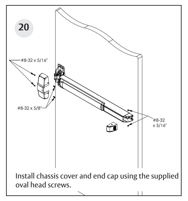
| #8-32 X 5/16" W/ #6 OVAL HEAD MACHINE SCREW | 4 |
(2) CHASSIS COVER
(2) END CAP |
| #8-32 X 5/8" W/ #6 OVAL HEAD MACHINE SCREW | 2 |
(2) CHASSIS COVER
RAIL SIDE |
|
1/4"-20 X 2-3/8" KNURLED FLAT HEAD
MACHINE SCREW |
2 |
(2) EXIT TRIM
(IF USED) |
Rim Exit Devices With All Standard Trim
Installation Instructions
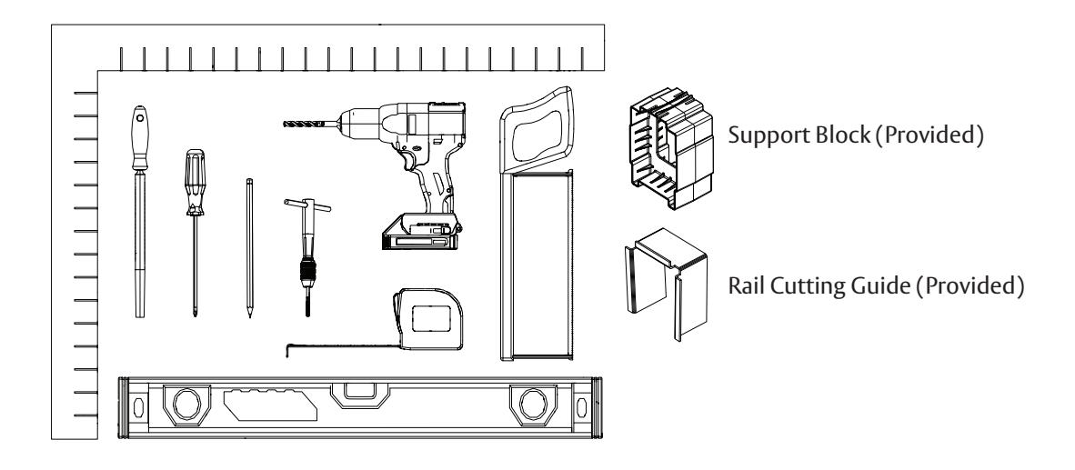
Tools Needed
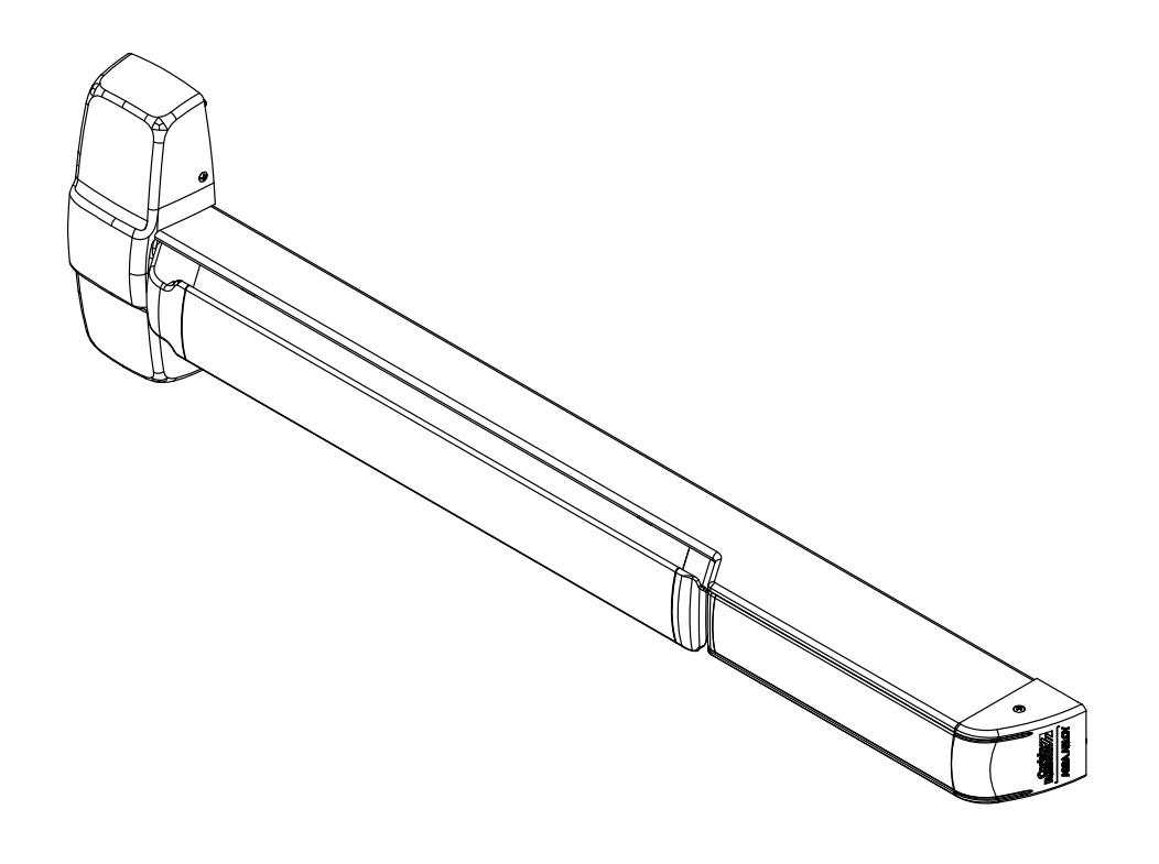
PED5200 & PED5200 A Rim Exit Device Exploded View
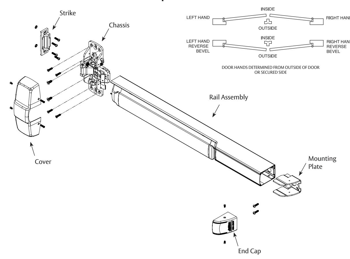
Rim Exit Devices With All Standard Trim
Installation Instructions

PED5200 M107 & PED5200 A Rim Exit Device Exploded View
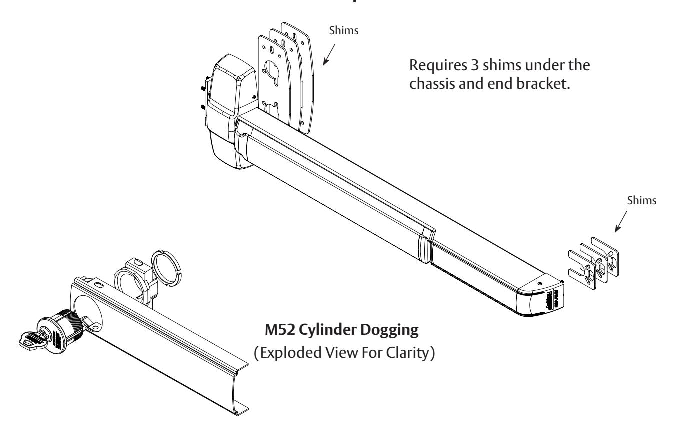
PED5200 HC & PED5200 A HC Rim Exit Device
(Not Shown)
Requires 2 shims under the chassis and end bracket.

Before installation:
- 1. Install mullion, if used.
- 2. Fit and hang door.
- 3. Check the box's label for the size of the exit device.
- 4. For wood doors, use wood screws and prep accordingly.
The surface of the door where the exit device is to be applied must be flush. Clear away any raised projections to allow exit device to rest on the flat surface of the door. If shim kit is required, contact your distributor.
Note: Please refer to trim and other installation instructions provided in the box.
Rim Exit Devices With All Standard Trim
Installation Instructions
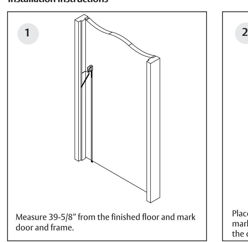
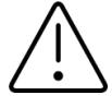
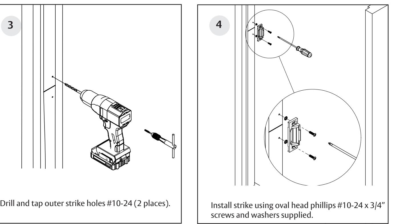
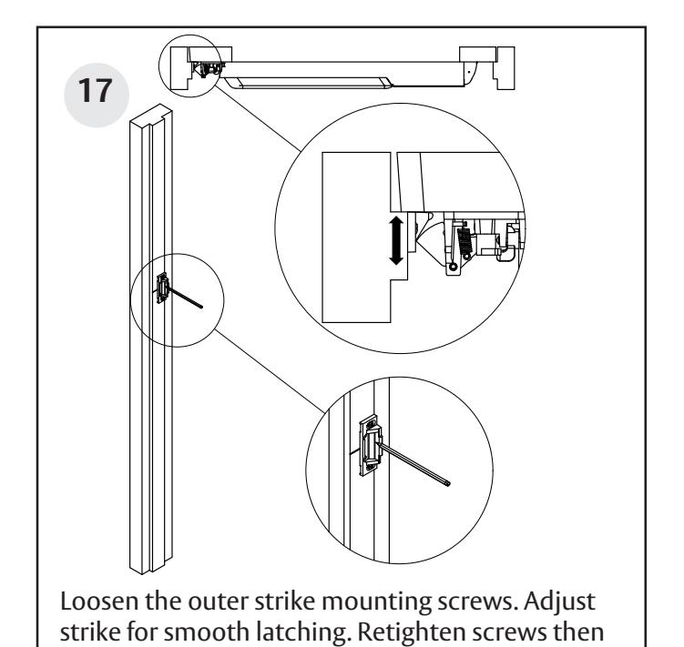
Place strike against frame, centered on the line marked in Step 1. With the strike pressed against the closed door, trace upper and lower strike slots.
Rim Exit Devices With All Standard Trim
Installation Instructions
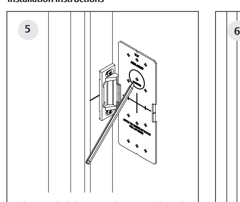
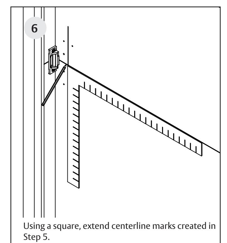
Place supplied plastic template against the strike. Mark centerlines and mounting holes per device function.
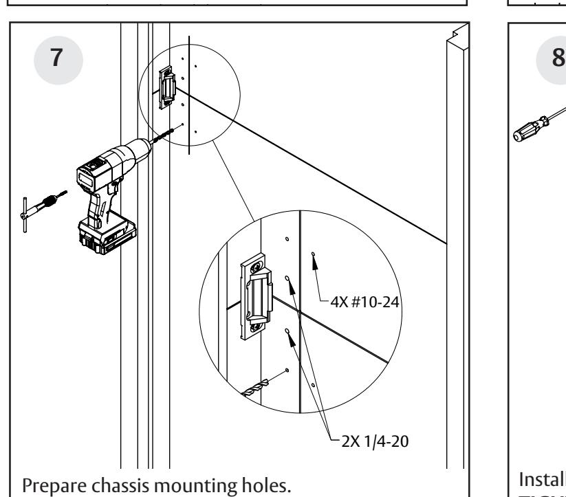
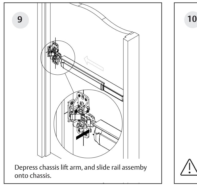
Install chassis mounting screws. DO NOT FULLY TIGHTEN SCREWS. If using thumbpiece trim/pull, reference steps 20b & 20c before proceeding.
FM577 1/23 For installation assistance contact Corbin Russwin 1-800-543-3658 • techsupport.corbinrusswin@assaabloy.com
• 2X 1/4-20 and 4X #10-24 Thread.
and Egress Hardware Group, Inc. is prohibited.
• Refer to supplied trim template as needed.
Rim Exit Devices With All Standard Trim
Installation Instructions
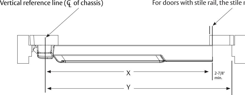
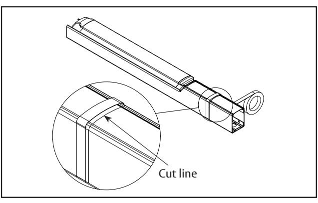
Rail cutting guide
If the rail doesn't need to be cut, continue to page 9, step 9. If the rail must be cut, follow these steps on page 7 and 8:
Refer to the individual exit device installation instructions for rail cutting requirements / restrictions. Instructions will vary based on device type and options.
• Determine cut off dimension "X" by subtracting 2-7/8" from dimension "Y". Mark cut off point on mounting rail. (See below.)
Do not cut closer than 1-5/8" from the the front edge of the rail insert.
| Information for Cutting Rails | |||
|---|---|---|---|
| Rail Sizes | Door Widths | ||
| Standard | Minimum | ||
| W032 | 32" | 24" | |
| W036 (Std.) | 36" | 33" | |
| W042 | 42" | 37" | |
| W048 | 48" | 43" | |
For doors with stile rail, the stile must overlap by 5/16" min.
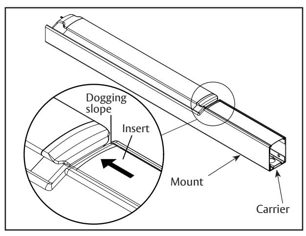
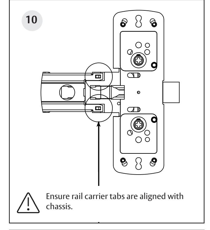
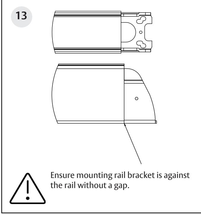
A. Ensure there isn't a gap between the insert and the dogging slope, and the carrier is flush with the mount.
Reproduction in whole or in part without the express written permission of ASSA ABLOY Access
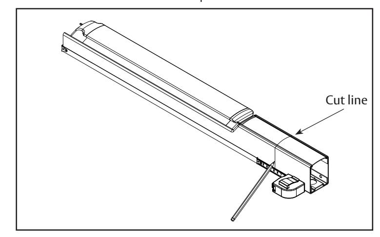
B. Mark rail at the required cut length.
FM577 1/23
and Egress Hardware Group, Inc. is prohibited.
Rim Exit Devices With All Standard Trim
Installation Instructions
Rail cutting guide, continued.

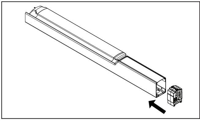
C. Ensure plastic insert support is installed under the cut line.
D. Wrap the rail and insert in masking tape, as shown.
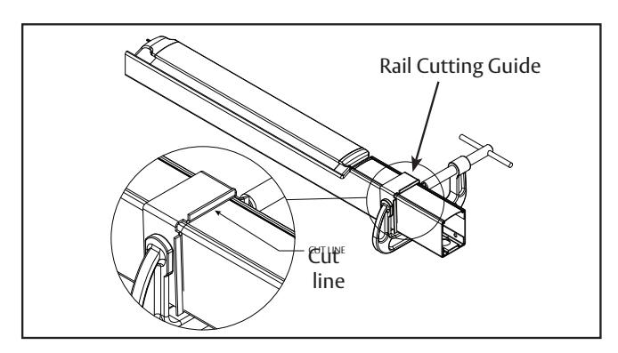
E. Place the rail cutting guide over the masking tape and align it with the cut line. Clamp the cut guide to the rail using a C-clamp.
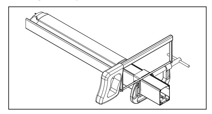
F. Using a hack saw with a new blade or a chop saw with a metal cutting blade, cut the rail, ensuring that the blade stays pressed against the rail cutting guide.
G. Deburr and smooth all cut edges with a file.
Rim Exit Devices With All Standard Trim
Installation Instructions


FM577 1/23
and Egress Hardware Group, Inc. is prohibited.
Reproduction in whole or in part without the express written permission of ASSA ABLOY Access
Rim Exit Devices With All Standard Trim
Installation Instructions
Rim Exit Devices With All Standard Trim
Installation Instructions

Rim Exit Devices With All Standard Trim
Installation Instructions
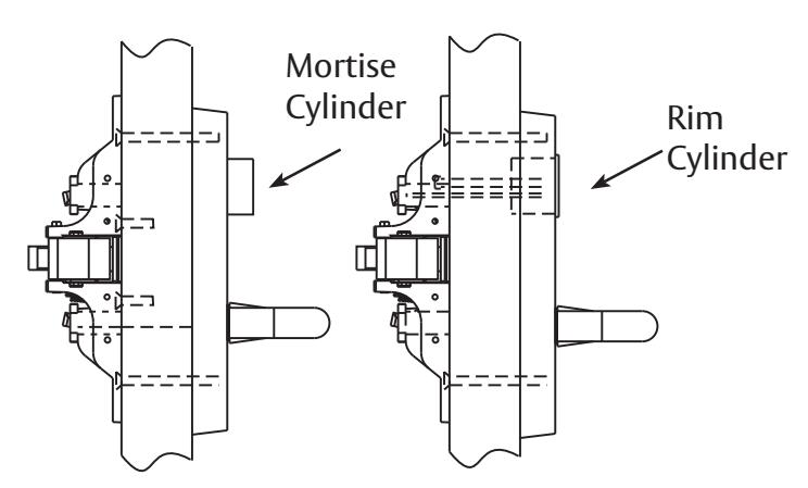
20a Rim cylinder mounting screw holes (if applicable) Trim mounting screw holes If 800 & 900 Series Exit Trim is used (See instruction sheet and template packed with trim.)
- Attach trim using the two (2) 1/4" 20 x 2-3/8" Phillips flat head machine screws through the appropriate mounting holes in the chassis.
- For rim cylinder functions, install cylinder through the trim using the two (2) #10-24 x 1-7/8" with #8 Phillips flat head machine screws through the appropriate mounting holes in the chassis, ensuring cylinder tail piece engages with the hub.
Rim Exit Devices With All Standard Trim

Installation Instructions
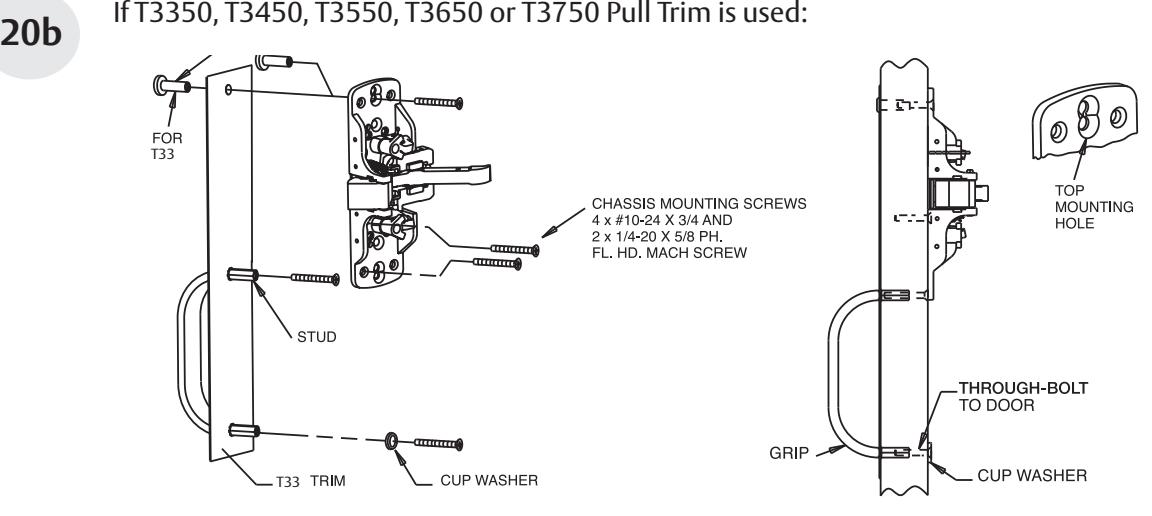
- Prepare the door with the provided template.
- Position the trim on the door with 1/4-20 x 5/8" machine screws as shown, using cup washer to thru bolt the bottom.
20c If T3357, T3457, T3557, T3657 or T3757 Pull Trim is used:
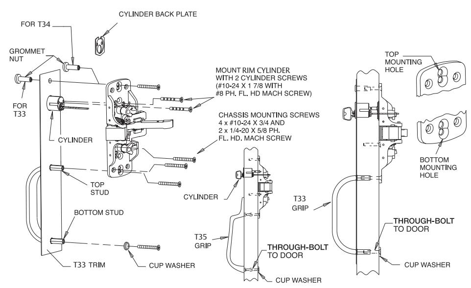
- Thru-bolt grommet nut throught the top chassis mounting hole.
- Thru-bolt top stud to bottom chassis mounting hole.
- Thru-bolt bottom stud through cup washer.
- Thru-bolt Sargent cylinder to chassis thru trim. If screw is too long, break off at notches as needed.
Rim Exit Devices With All Standard Trim
Installation Instructions

22 (M91) Latch Bolt Monitoring Adjustment
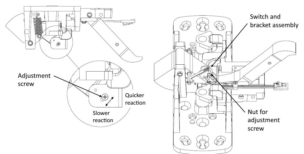
- Loosen adjustment screw and nut.
- Rotate switch.
- Tighten adjustment screw and nut.
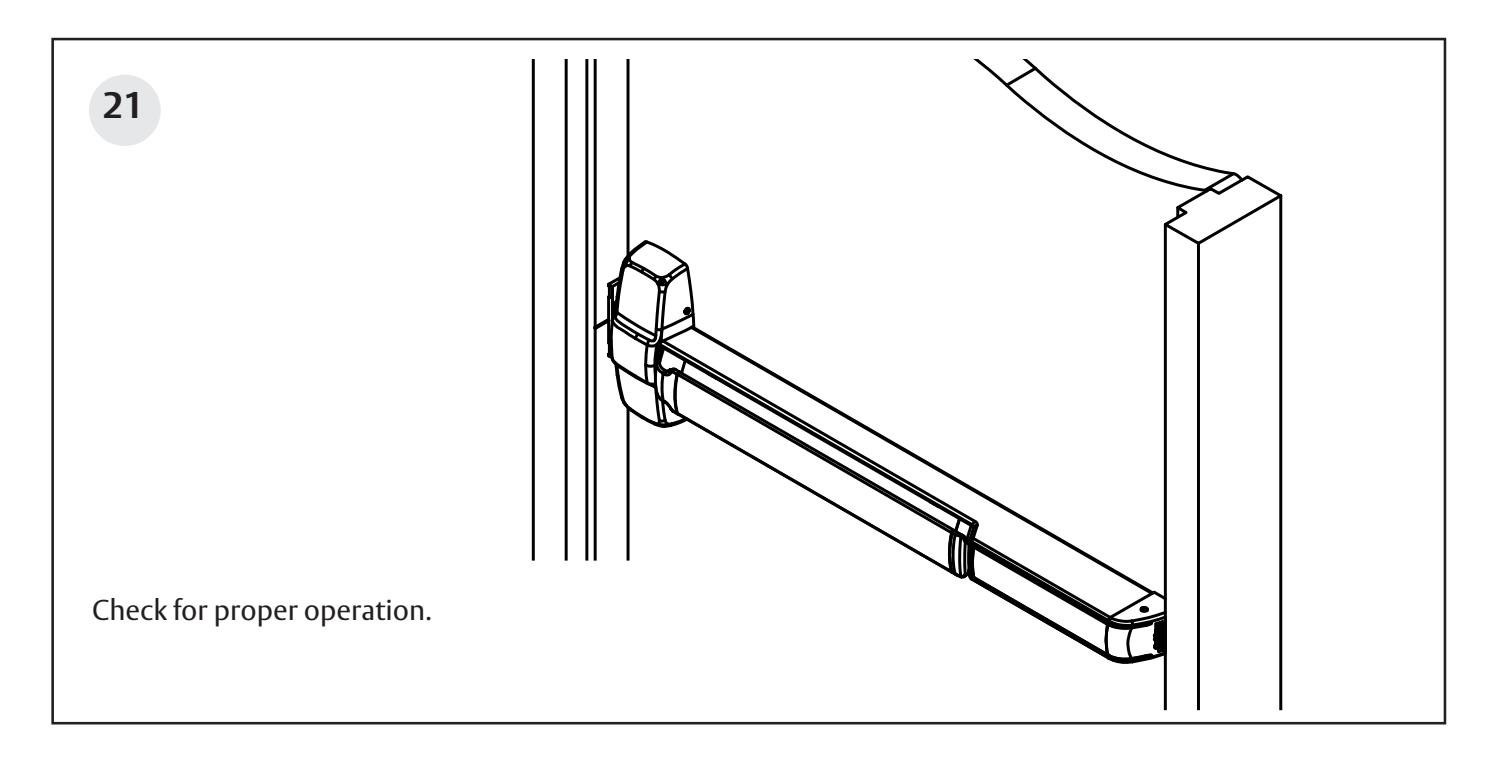
- Check operation.
For more information scan the QR code.

Rim Exit Devices With All Standard Trim
Installation Instructions

and Egress Hardware Group, Inc. is prohibited.