Corbin Russwin PED4000 Series PED4800(A) Narrow Stile CVR Aluminum and Metal Doors Installation Instructions_FM582
Open the original PDF document
View PDFInstallation Instructions

PED4800 Series (AD, MD, and A MD)
Narrow Stile Concealed Vertical Rod Exit Devices

This product can expose you to lead which is known to the state of California to cause cancer and birth defects or other reproductive harm. For more information go to www. P65warnings.ca.gov.
1-800-543-3658 • techsupport.corbinrusswin@assaabloy.com
Copyright © 2023 ASSA ABLOY Access and Egress Hardware Group, Inc. All rights reserved. Reproduction in whole or in part without the express written permission of ASSA ABLOY Access and Egress Hardware Group, Inc. is prohibited. Patent pending and/or patent www.assaabloydss.com/patents.

Attention Installer: Improper installation may result in damage to the product and void the factory warranty.
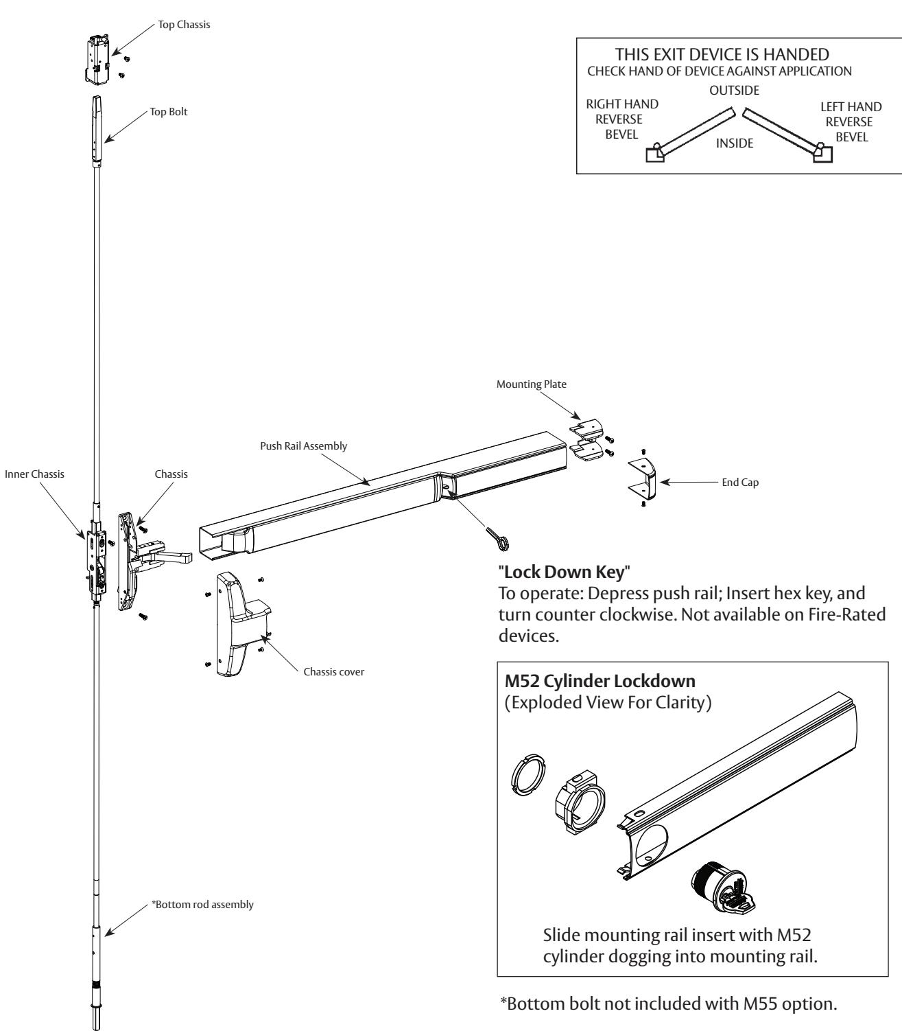
Narrow Stile Concealed Vertical Rod Exit Device
Installation Instructions

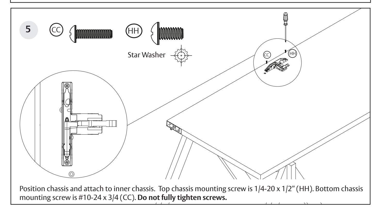
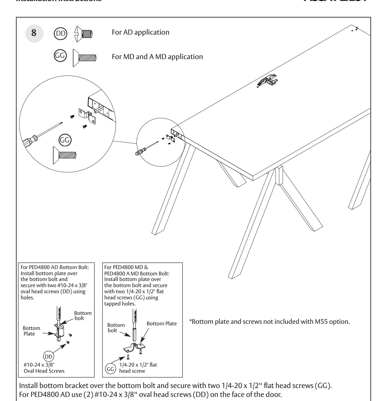
Screws used for PED4800 AD, PED4800 MD, and PED4800 A MD, Exit Device Installation
| SCREW |
TOTAL QTY
SUPPLIED |
WHERE USED | ||
|---|---|---|---|---|
| HH |
1/4"-20 X 1/2" ROUND HEAD
MACHINE SCREW |
1 |
(1) CHASSIS
TOP MOUNTING HOLE |
|
| CC |
#10-24 X 3/4" ROUND HEAD
MACHINE SCREW |
3 |
(1) CHASSIS TO INNER CHASSIS
BOTTOM MOUNTING HOLE (2) REAR MOUNTING PLATE |
|
| DD |
#10-24 X 3/8" OVAL HEAD
MACHINE SCREW |
4 |
(2) TOP CASE
(2) BOTTOM PLATE (IF AD) |
|
| GG |
1/4"-20 X 1/2" FLAT HEAD
MACHINE SCREW |
2 |
(2) BOTTOM PLATE
(MD OR FIRE RATED) |
|
| EE |
#10-24 X 1/2" U'CUT FLAT HEAD
MACHINE SCREW |
5 |
(1) INNER CHASSIS
TOP MOUNTING HOLE (2) 640 OR 650 STRIKE, TOP (METAL FRAME) (2) 640 OR 650 STRIKE, BOTTOM (METAL FRAME) |
|
|
#10 X 1-1/4 FLAT HEAD
WOOD SCREW |
2 |
(2) 650 STRIKE, TOP
(WOOD FRAME) (2) 650 STRIKE, BOTTOM (WOOD FRAME) |
||
|
1/4"-20 X 2" FLAT HEAD
MACHINE SCREW W/ANCHOR |
2 |
(2) 606 BOTTOM STRIKE
(FIRE RATED) |
||
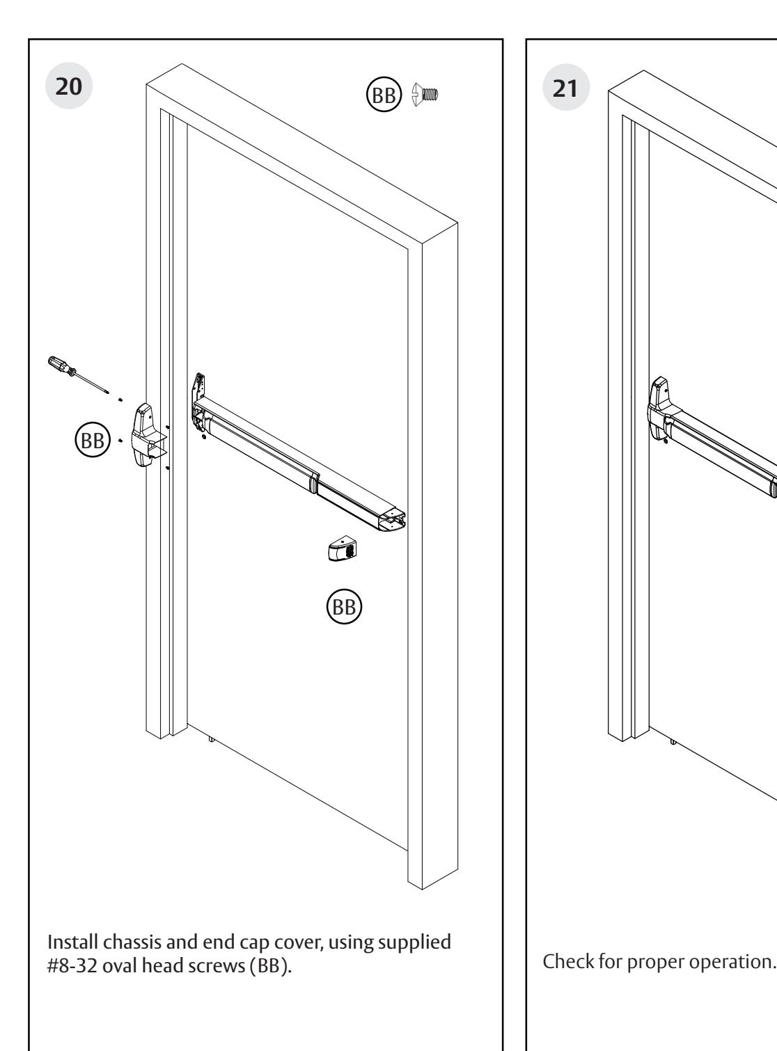
| BB |
#8-32 X 5/16" W/ #6 OVAL HEAD
MACHINE SCREW |
4 |
(2) CHASSIS COVER
FRAME SIDE (2) END CAP |
|
|
#8-32 X 5/8" W/ #6 OVAL HEAD
MACHINE SCREW |
2 |
(2) CHASSIS COVER
RAIL SIDE |
||
|
1/4"-20 X 2-3/8" KNURLED FLAT HEAD
MACHINE SCREW |
2 |
(2) EXIT TRIM
(IF USED) |
||
Narrow Stile Concealed Vertical Rod Exit Device
Installation Instructions

Equipment Needed
Tools
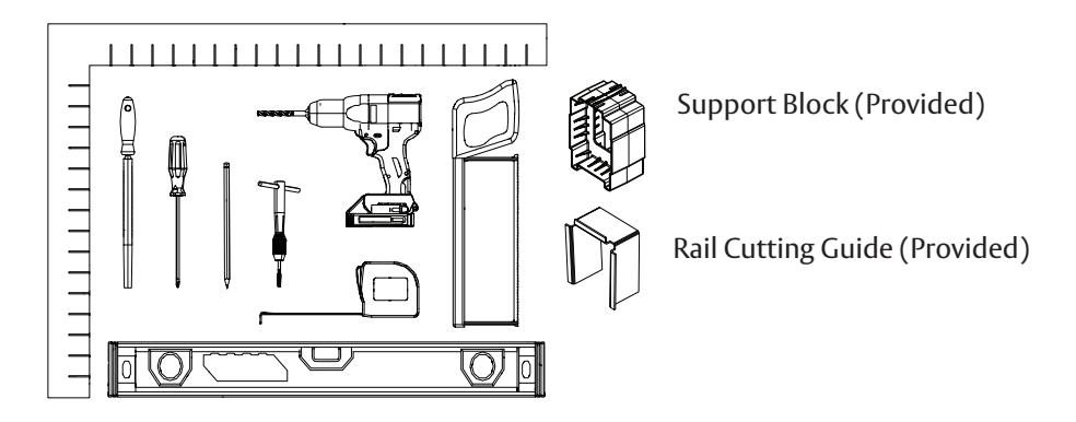
Strike Packs
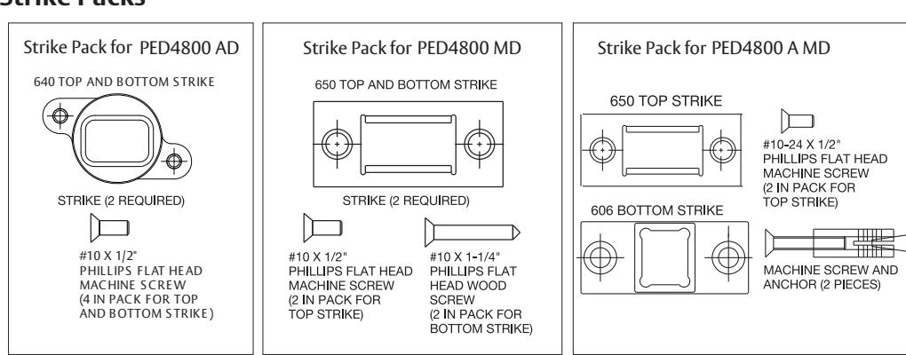
*Bottom Strike kits are not included with M55 option.

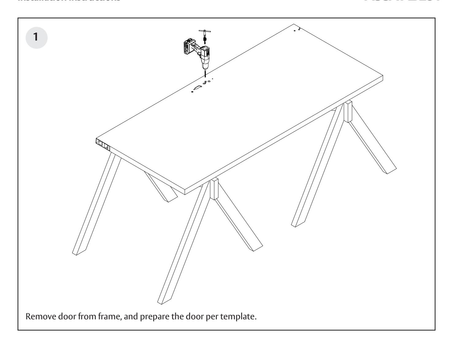
Before installation:
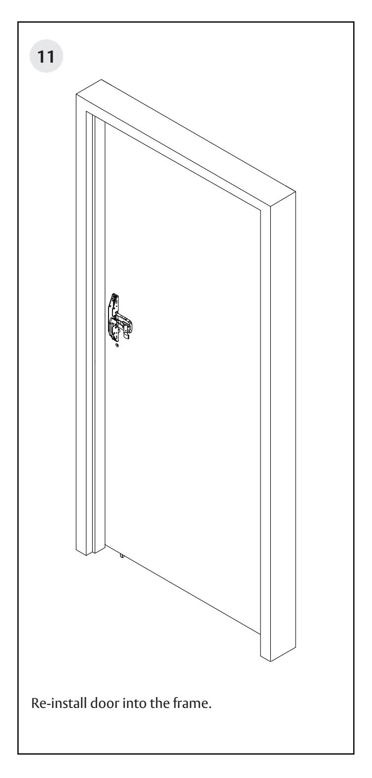
- 1. Fit and hang door.
- 2. Check the box's label for the size of the exit device.

The surface of the door where the exit device is to be applied must be flush. Clear away any raised projections to allow exit device to rest on the flat surface of the door. If shim kit is required, contact your distributor.
Note: Please refer to trim and other installation instructions provided in the box.
Narrow Stile Concealed Vertical Rod Exit Device

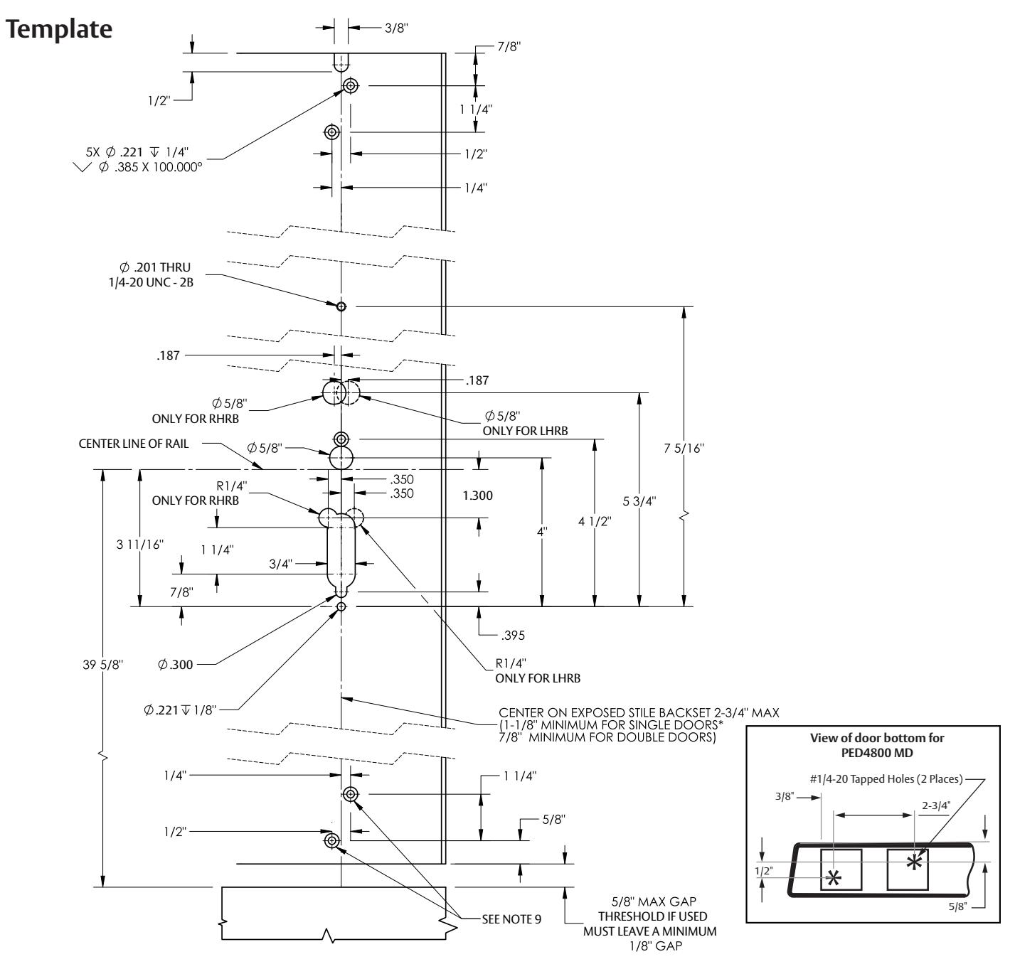
- LS: DOOR PREPARATION SHOWN FOR INSIDE DOOR ONLY. IF OUTSIDE PULL AND/OR OUTSIDE CONTROL IS USED, SEE APPROPRIATE DOOR TEMPLATE FOR OUTSIDE DOOR PREP. *MIN BACKSET FOR SINGLE DOOR IS BASED ON 1/2" FRAME STOP, LARGER FRAME STOPS REQUIRE LARGER BACKSET. SURFACE OF DOOR WHERE EXIT DEVICE IS TO BE APPLIED, MUST BE FLUSH. WE RECOMENDED THAT ALL TAPPED HOLES BE DRILLED AND TAPPED IN FIELD.
- TOLERANCE ALL FRACTIONAL DIMENSIONS ±1/64". BOTTOM AND TOP STRIKES MUST BE USED, SEE STRIKE TEMPLATE NO. MEDT6. SEE TEMPLATE NO. MEDIT FOR AUX CONTROL IF REQ'D. FOR DEVICES WITH NO BOTTOM ROD, HOLES FOR BOTTOM CASE ARE NOT REQUIRED.
Narrow Stile Concealed Vertical Rod Exit Device
Installation Instructions
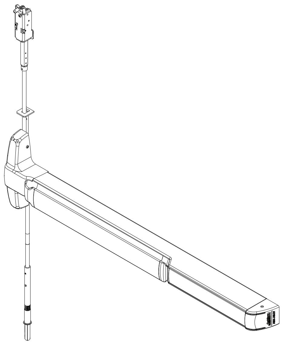
Product Overview

Narrow Stile Concealed Vertical Rod Exit Device
Installation Instructions

Patent pending and/or patent www.assaabloydss.com/patents.
Narrow Stile Concealed Vertical Rod Exit Device
Narrow Stile Concealed Vertical Rod Exit Device
Installation Instructions

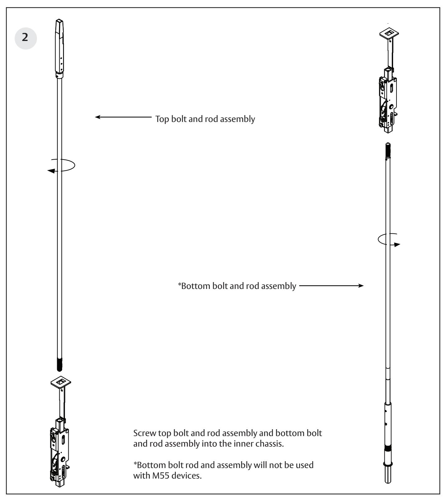
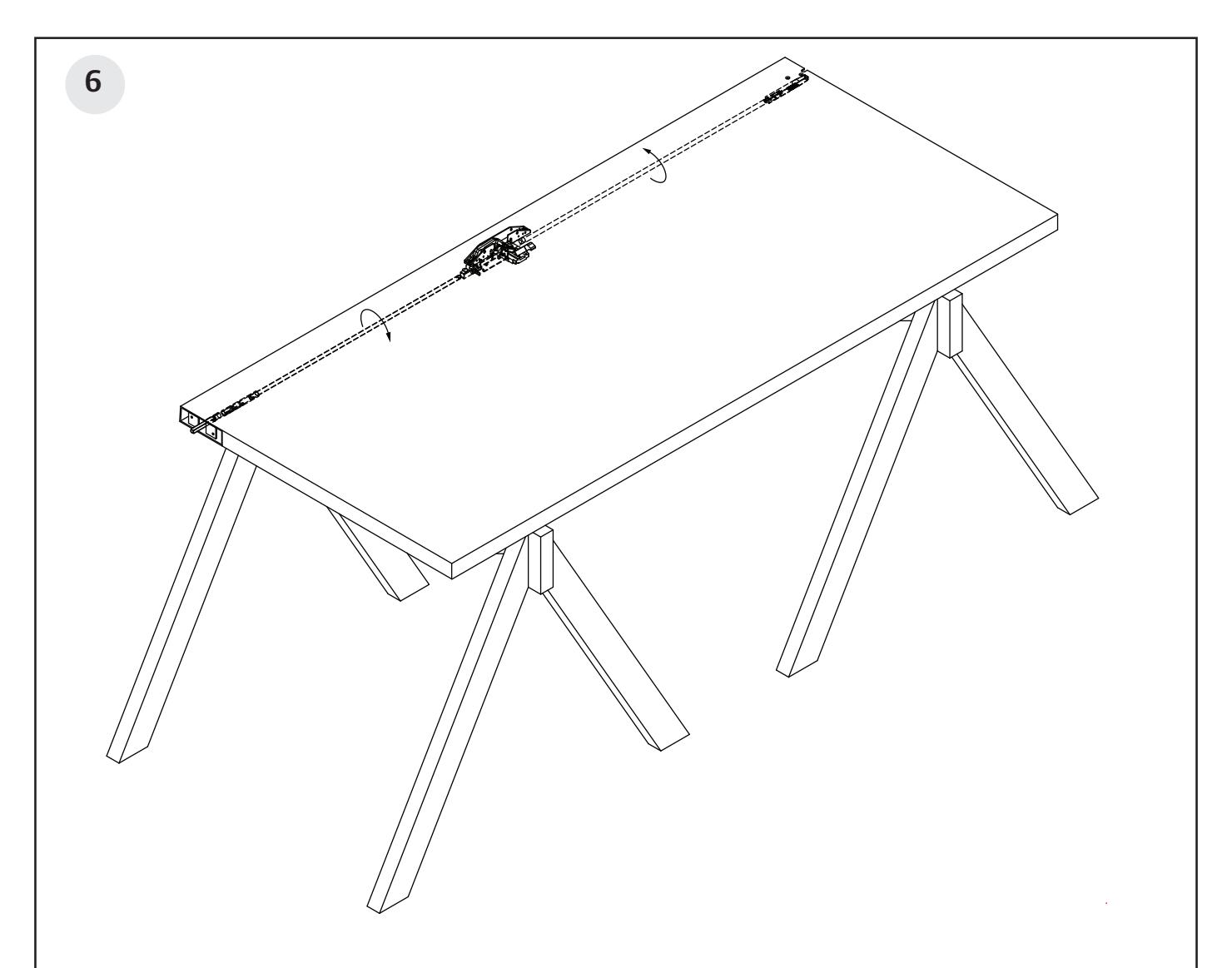
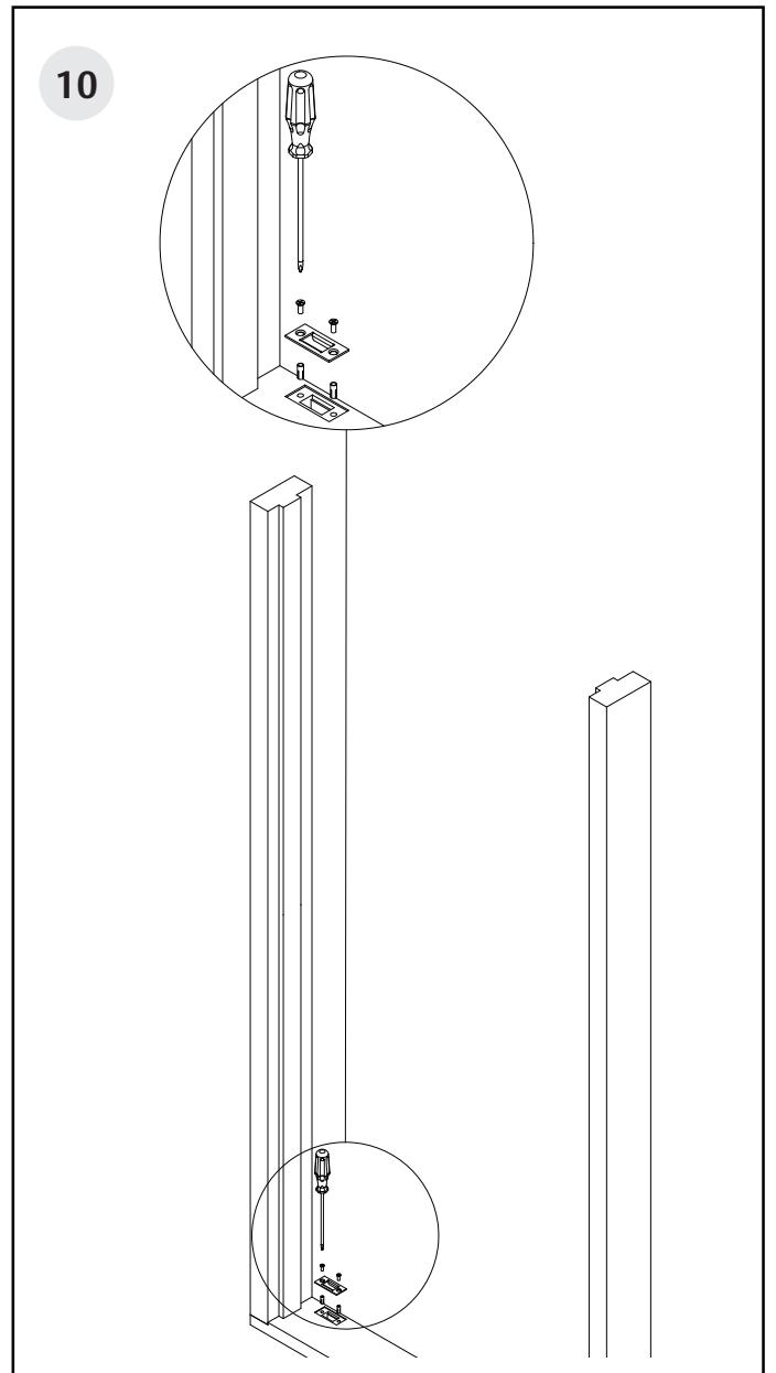
Feed rod and inner chassis assembly into the door. Ensure teeth face down and top bolt teeth are opposite the inside door prep.
Patent pending and/or patent www.assaabloydss.com/patents.
Narrow Stile Concealed Vertical Rod Exit Device
Installation Instructions

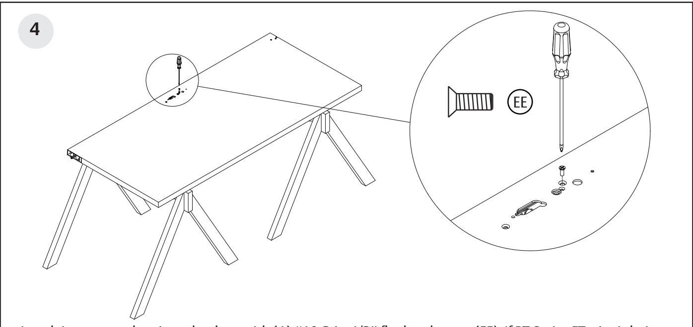
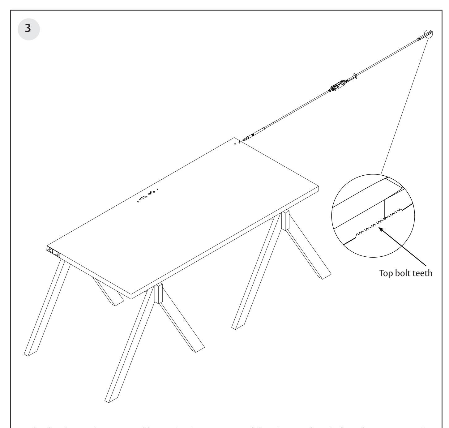
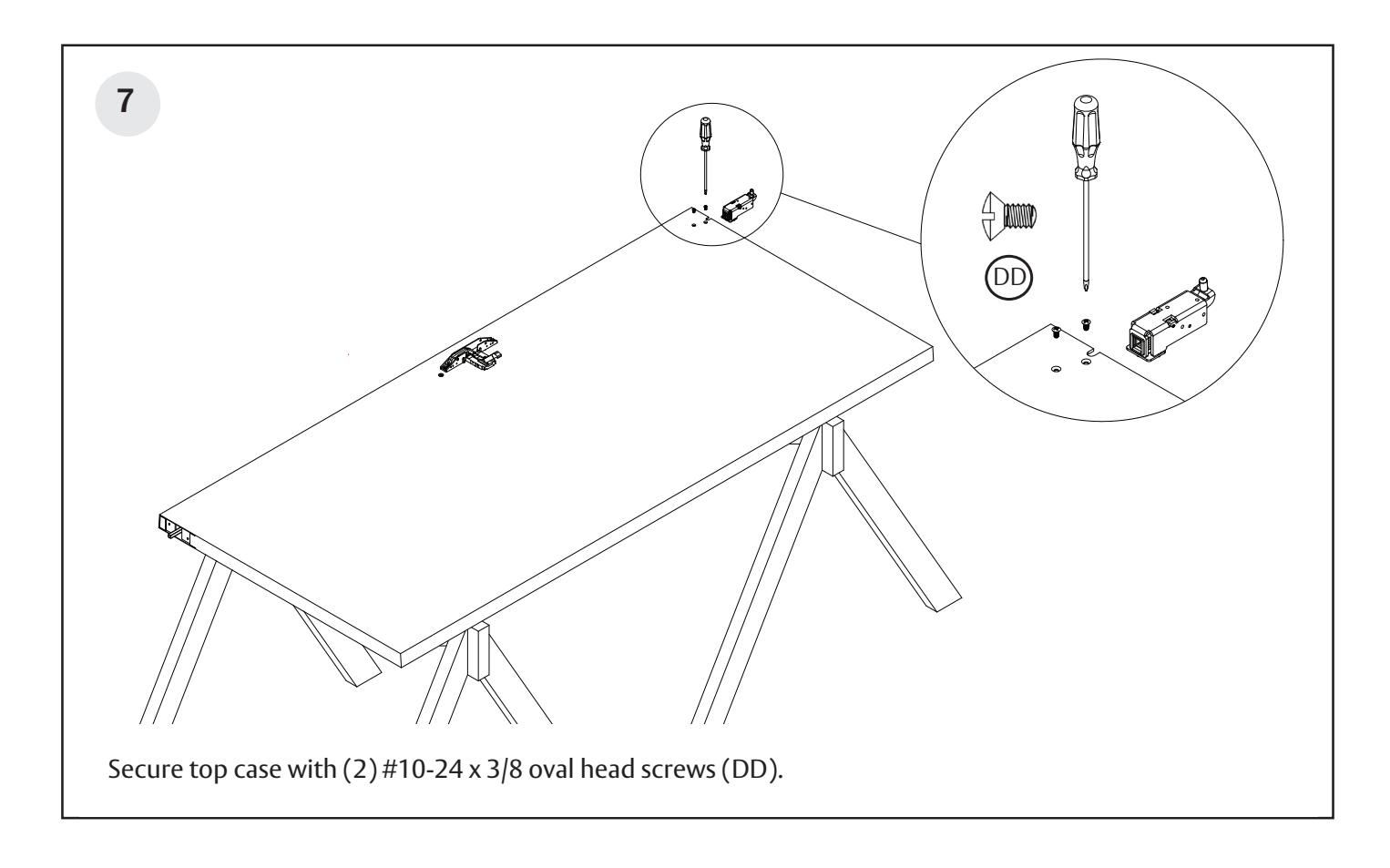
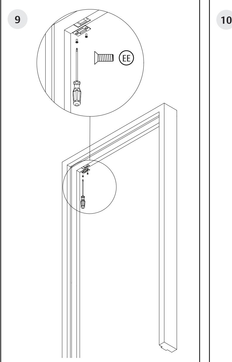
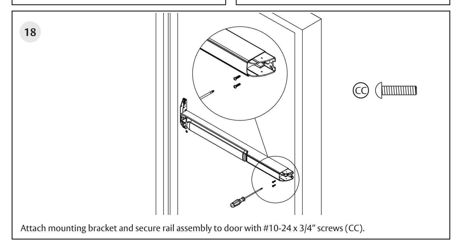
Attach inner case chassis to the door with (1) #10-24 x 1/2" flat head screw (EE). If PT Series ET trim is being used, it must be installed at this point. See trim installation instructions.
Narrow Stile Concealed Vertical Rod Exit Device
Installation Instructions

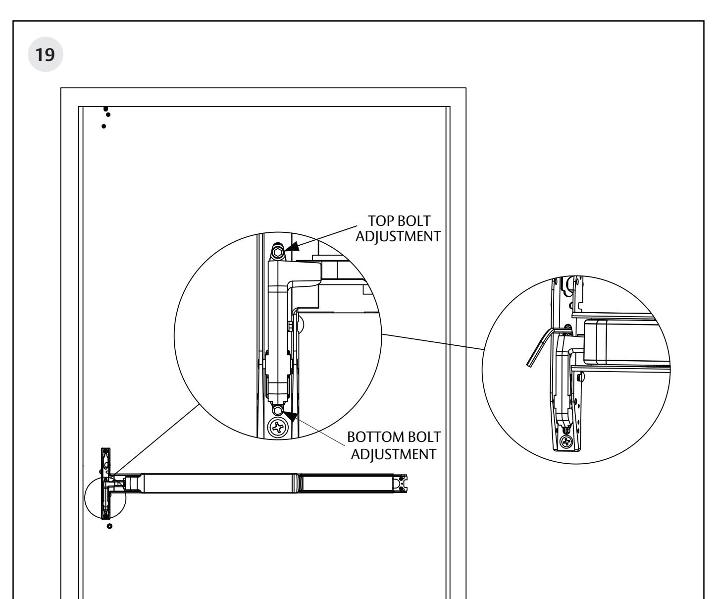
Adjusting the top bolt and rod assembly
- 1/8" gap or less between door top and frame: Rotate bolt to make it even with the top of the door.
- 1/8" gap or greater: Bolt must extend above the door, equal to the gap, minus 1/8".
Adjusting the bottom bolt and rod assembly (Not needed for NB exit devices)
- 1/8" gap or less between door bottom and high point: Rotate bolt to make it even with the top of the door.
- 1/8" gap or greater: Bolt must extend below the door, equal to the gap, minus 1/8".
Note: Rod must be retracted while adjusting bolt projection. Depress chassis lift arm to retract top bolt and rod assembly.
Narrow Stile Concealed Vertical Rod Exit Device
Installation Instructions

11
Narrow Stile Concealed Vertical Rod Exit Device

Narrow Stile Concealed Vertical Rod Exit Device

- For PED4800 MD & PED4800 A MD: Attach 650 strike to frame with (2) #10-24 x 1/2" flat head screws (EE).
- For PED4800 AD: Attach 640 strike to frame with (2) #10-24 x 1/2" flat head screws (EE).
- For PED4800 MD & PED4800 A MD: Attach 650 bottom strike to floor with anchors and supplied fasteners.
- For PED4800 A MD: Attach 606 bottom strike to floor with anchors and supplied fasteners.
- For PED4800 AD: Attach 640 strike to threshold with supplied fasteners.
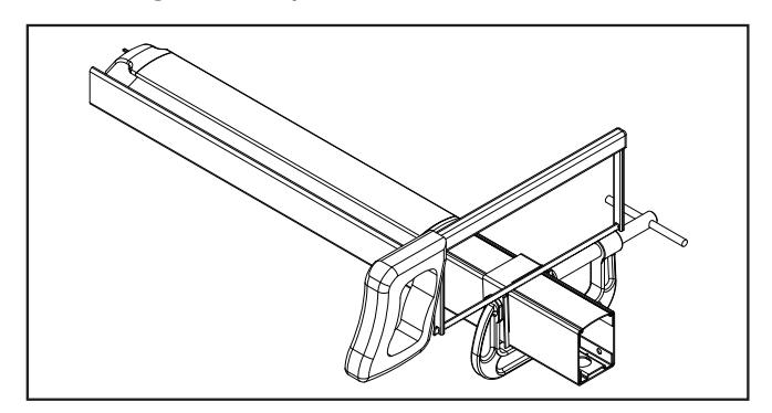
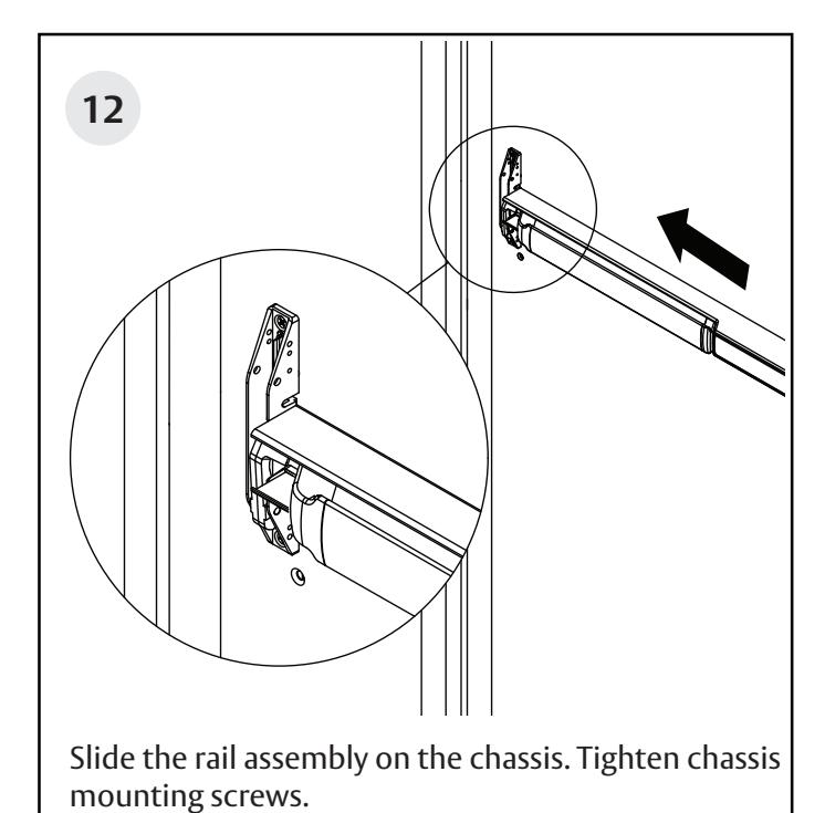
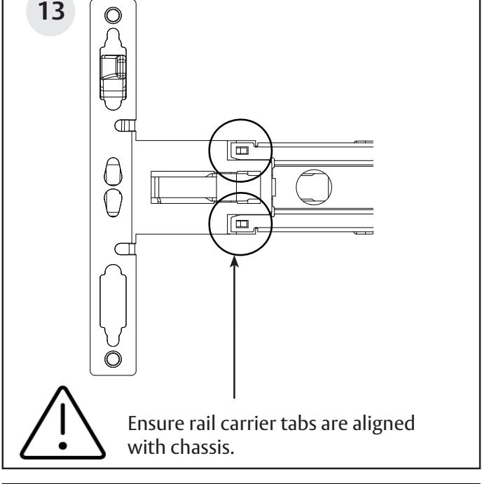
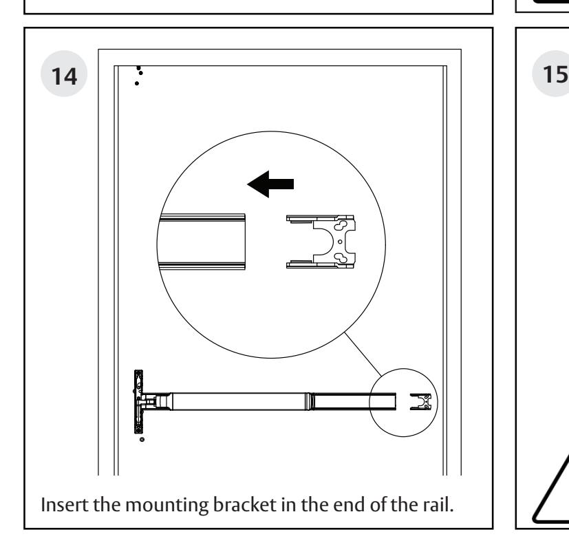
Narrow Stile Concealed Vertical Rod Exit Device

Narrow Stile Concealed Vertical Rod Exit Device
Installation Instructions
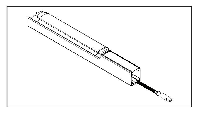
Rail cutting guide
If the rail doesn't need to be cut, continue to page 17, step 12. If the rail must be cut, follow these steps on page 15 and 16:
Refer to the individual exit device installation instructions for rail cutting requirements / restrictions. Instructions will vary based on device type and options.
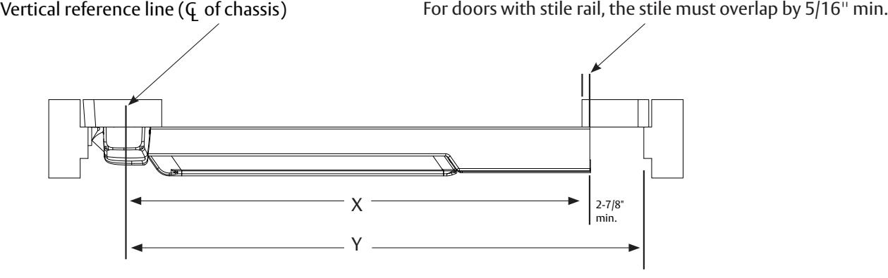
• Determine cut off dimension "X" by subtracting 2-7/8" from dimension "Y". Mark cut off point on mounting rail. (See below.)
| Information for Cutting Rails | |||||
|---|---|---|---|---|---|
| Door Widths | |||||
| Rail Sizes | Standard | Minimum | |||
| W032 | 32" | 24" | |||
| W036 (Std.) | 36" | 33" | |||
| W042 | 42" | 37" | |||
| W048 | 48" | 43" | |||
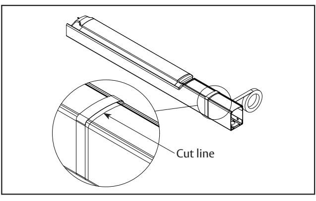
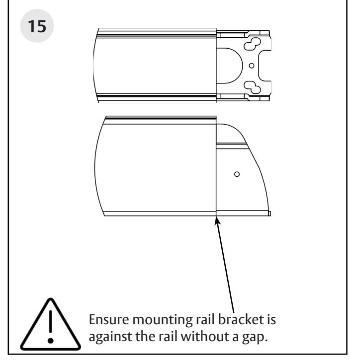
Do not cut closer than 1-5/8" from the the front edge of the rail insert.
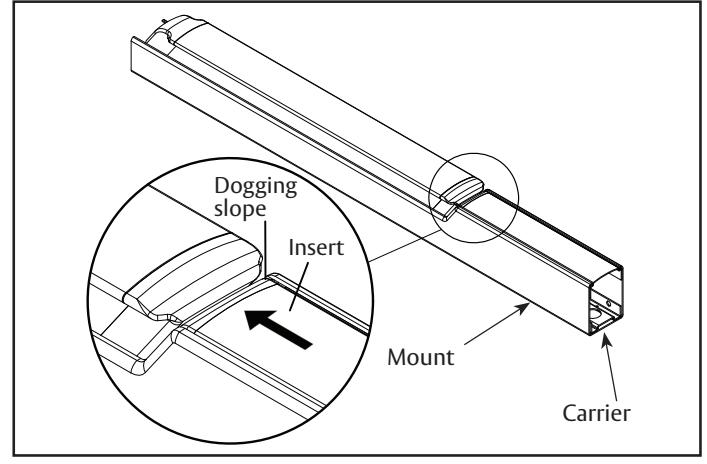
A. Ensure there isn't a gap between the insert and the dogging slope, and the carrier is flush with the mount.
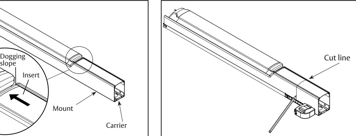
B. Mark rail at the required cut length.
Narrow Stile Concealed Vertical Rod Exit Device
Installation Instructions
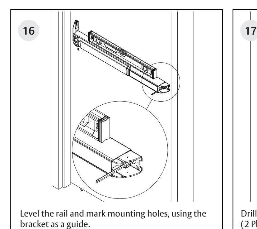
Rail cutting guide, continued.

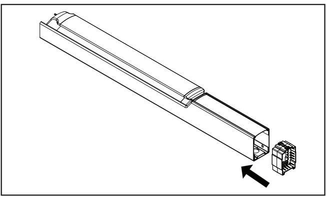
C. Ensure plastic insert support is installed under the cut line.
D. Wrap the rail and insert in masking tape, as shown.
E. Place the rail cutting guide over the masking tape and align it with the cut line. Clamp the cut guide to the rail using a C-clamp.
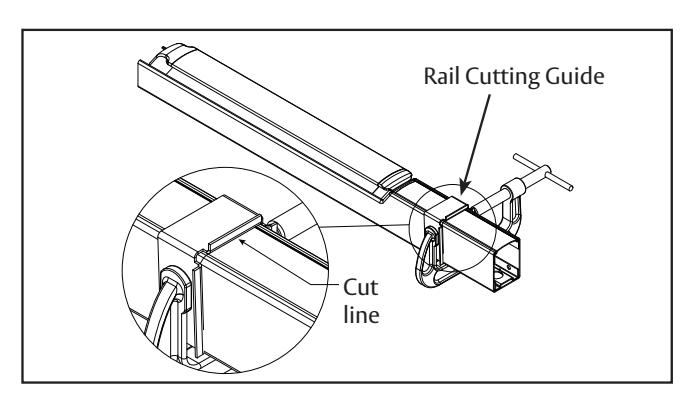
F. Using a hack saw with a new blade or a chop saw with a metal cutting blade, cut the rail, ensuring that the blade stays pressed against the rail cutting guide.
G. Deburr and smooth all cut edges with a file.
Narrow Stile Concealed Vertical Rod Exit Device


Narrow Stile Concealed Vertical Rod Exit Device

Narrow Stile Concealed Vertical Rod Exit Device
Installation Instructions
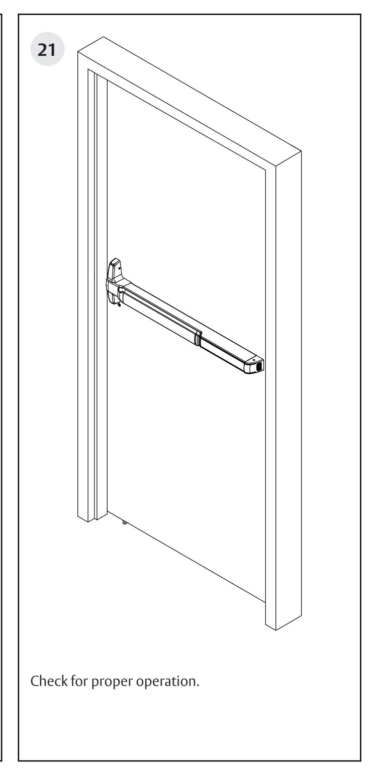
If adjustments are needed, before closing the door check the following:
- Push rail in to retract bolts.
- Bolts stay retracted (hold back).
- Bolts release when the door closes. The button inside the top of the door hits the frame.
- The bolt engages with the strike 1/4" 5/16".
For final adjustment, close door to adjust.
• Use 5/32" Allen wrench to adjust projection. Turn clockwise to adjust the bolt back into the door. Turn counter clockwise to extend the bolt.
19