Corbin Russwin Museo Mortise Lock Installation Instructions
Open the original PDF document
View PDF

MORTISE LOCK INSTALLATION INSTRUCTIONS
MUSEO DESIGNER TRIM
FM 601 Rev. C (10/18)


This product can expose you to lead which is known to the state of California to cause cancer and birth defects or other reproductive harm. For more information go to www.P65warnings.ca.gov.
08/2018

TABLE OF CON TENTS:
|
DOOR P
RE PARATION |
1 |
|---|---|
|
LOCK
AN DIN G |
2 |
|
FULL WORK
IN G TRIM |
|
|
SE
CT ION AL R & L E SCU TCH EON |
3
6 |
|
HALF
WORK IN G TRIM |
|
|
SE
CT ION AL |
8 |
|
R &
L E SCU TCH EON |
10 |
| FULL DUMMY TRIM | |
|
SE
CT ION AL |
12 |
|
R &
L E SCU TCH EON |
13 |
|
HALF
DUMMY TRIM |
|
|
SE
CT ION AL |
14 |
|
R &
L E SCU TCH EON |
15 |
|
SE
CON DARY TRIM ATTACH MENT |
|
|
EMERGE
NCY K EY P LATE |
16 |
LOCK H AN DIN G IS CRITICAL TO ENSU RE LOCK FUNCT ION S P ROPERLY

DOOR P REPARATION :
| TEMPLATE | |
|---|---|
|
FULL WORK
IN G TRIM : |
|
|
LOCK
-BOD Y P RE P |
T3104
6 |
|
SE
CT ION AL NO AD DIT ION AL P RE P RE QUIRE D BE YON |
D T3104
6 |
|
R &
L E SCU TCH EON |
T3104
7 |
|
HALF
WORK IN G TRIM : |
|
|
LOCK
-BOD Y P RE P |
T3116
2 |
|
SE
CT ION AL NO AD DIT ION AL P RE P RE QUIRE D BE YON |
D T3116
2 |
|
R &
L E SCU TCH EON |
T3116
4 |
|
FULL DUMMY TRIM
: |
|
|
SE
CT ION AL |
T3116
3 |
|
R &
L E SCU TCH EON |
T306
51 |
|
HALF
DUMMY TRIM : |
|
|
SE
CT ION AL |
T3116
3 |
|
R &
L E SCU TCH EON |
T306
52 |
ALL W ORK IN G TRIM M UST F IRST BE P REPARED FOR THE LOCK-BODY THEN FOR THE TRIM
ALL TEMPLATES CAN BE F OU ND AT WWW.CORBIN RU SSW IN .COM
IN STALLATION IN ST RU CT IONS
MUSEO Trim Instructions FM 601 Rev. C (10/18)

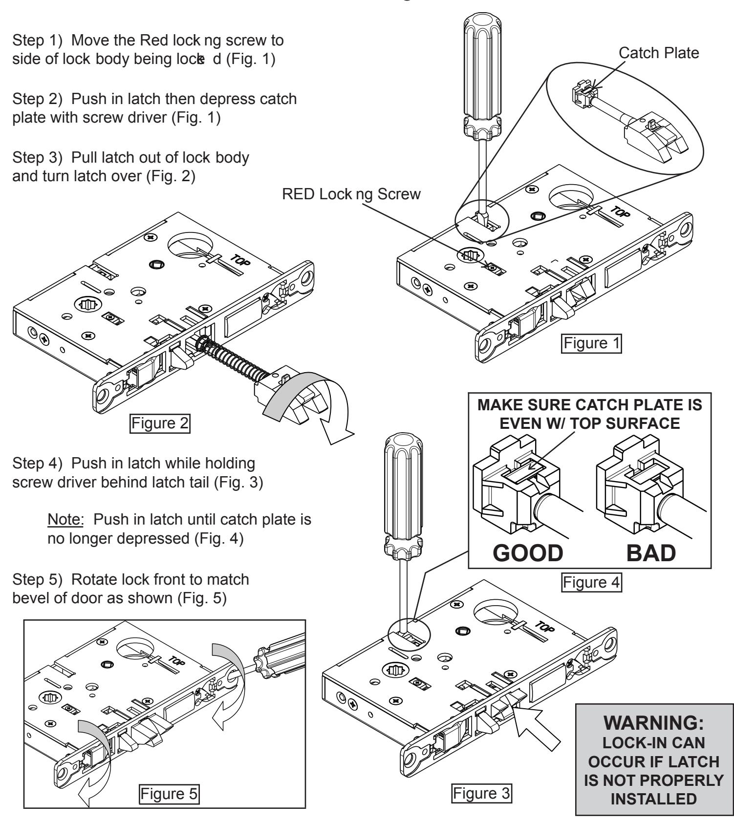
Mortise Lock Handing Instructions

FULL W ORK IN G TRIM IN STALLATION
SE CT ION AL:
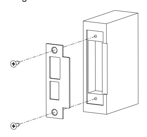
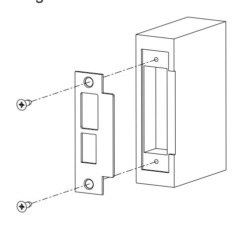
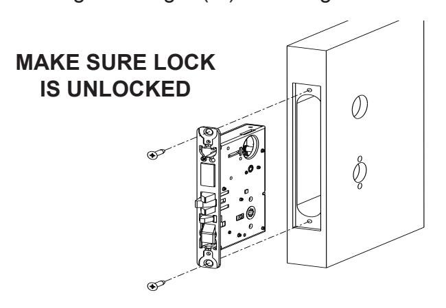
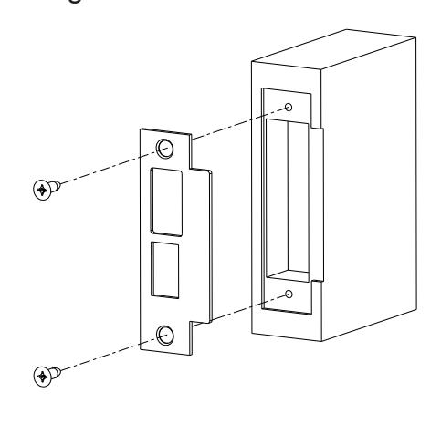
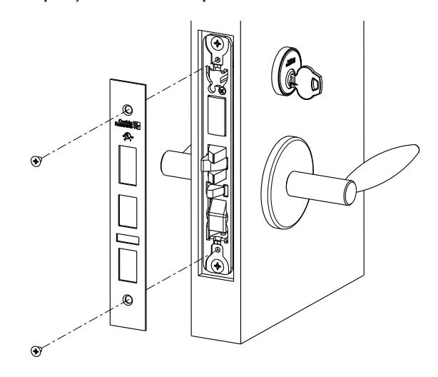
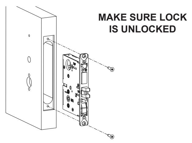
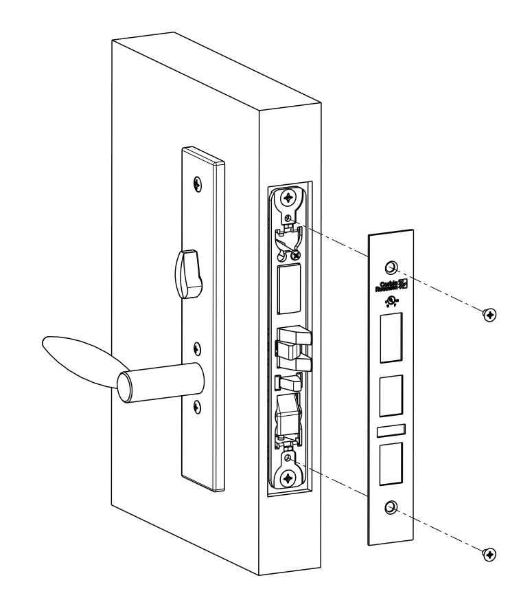
Step 1) Install strike with shorter ( 3/4") mounting screws
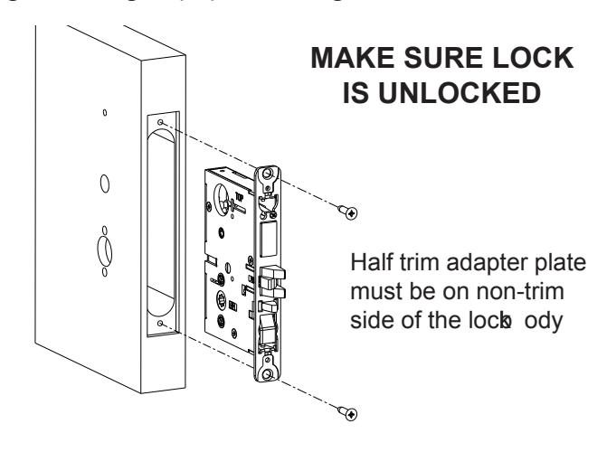
Step 2) Insert mortise lock into door and hand tighten longer ( 1") mounting screws

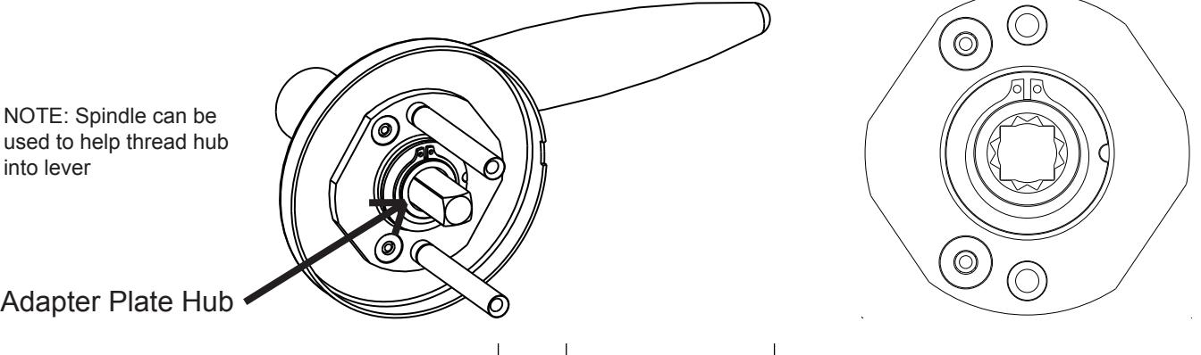
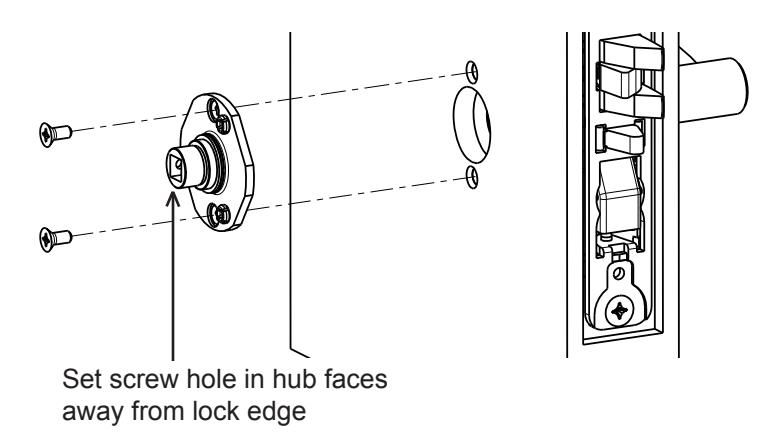
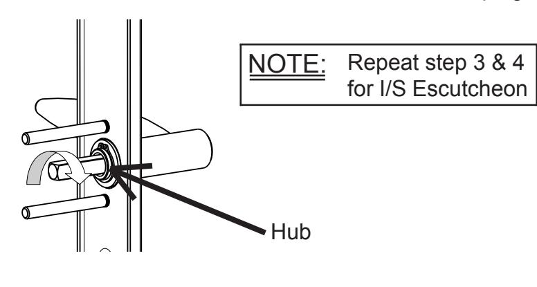
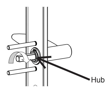
Step 3) Thread adapter plate hub into lever and fully tighten
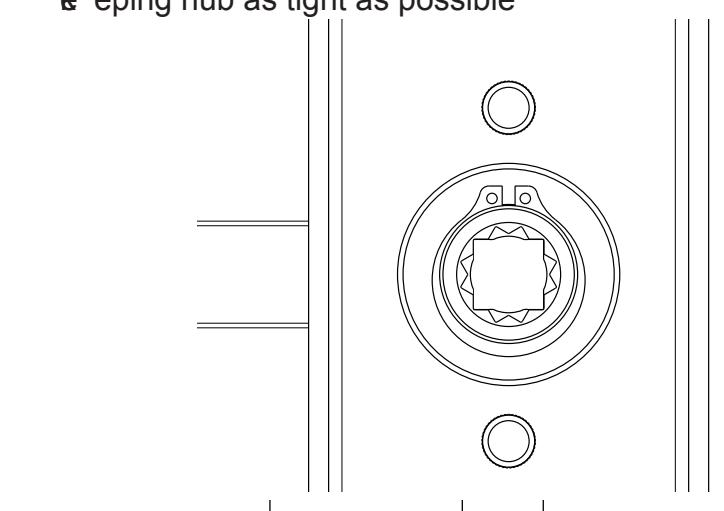
Step 4) Align adapter plate hub with square hole in lever; ke eping hub as tight as possible
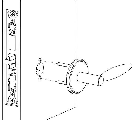
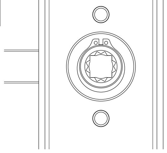
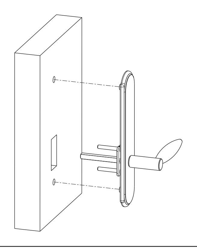
Step 5) Install O/S trim assembly

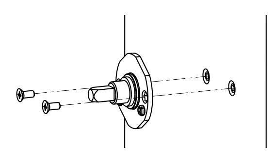
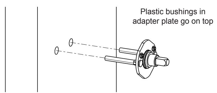
Step 6) Install I/S adapter plate

Lever Lever
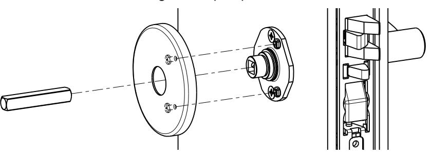
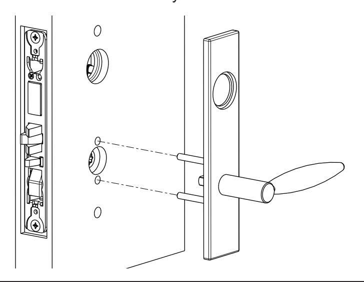
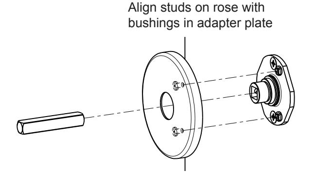
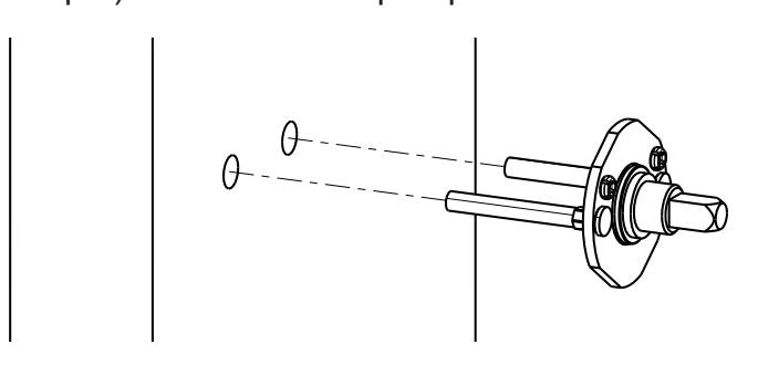
Step 7) Install I/S spindle and rose
Align studs on rose with bushings in adapter plate
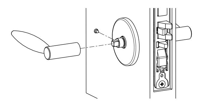
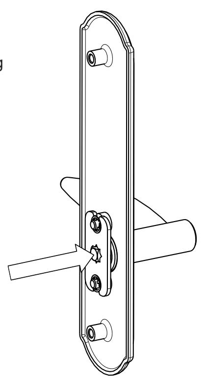
Step 8) Install I/S lever with set screw

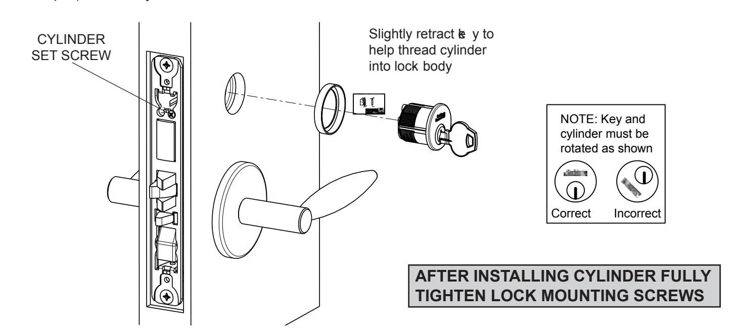
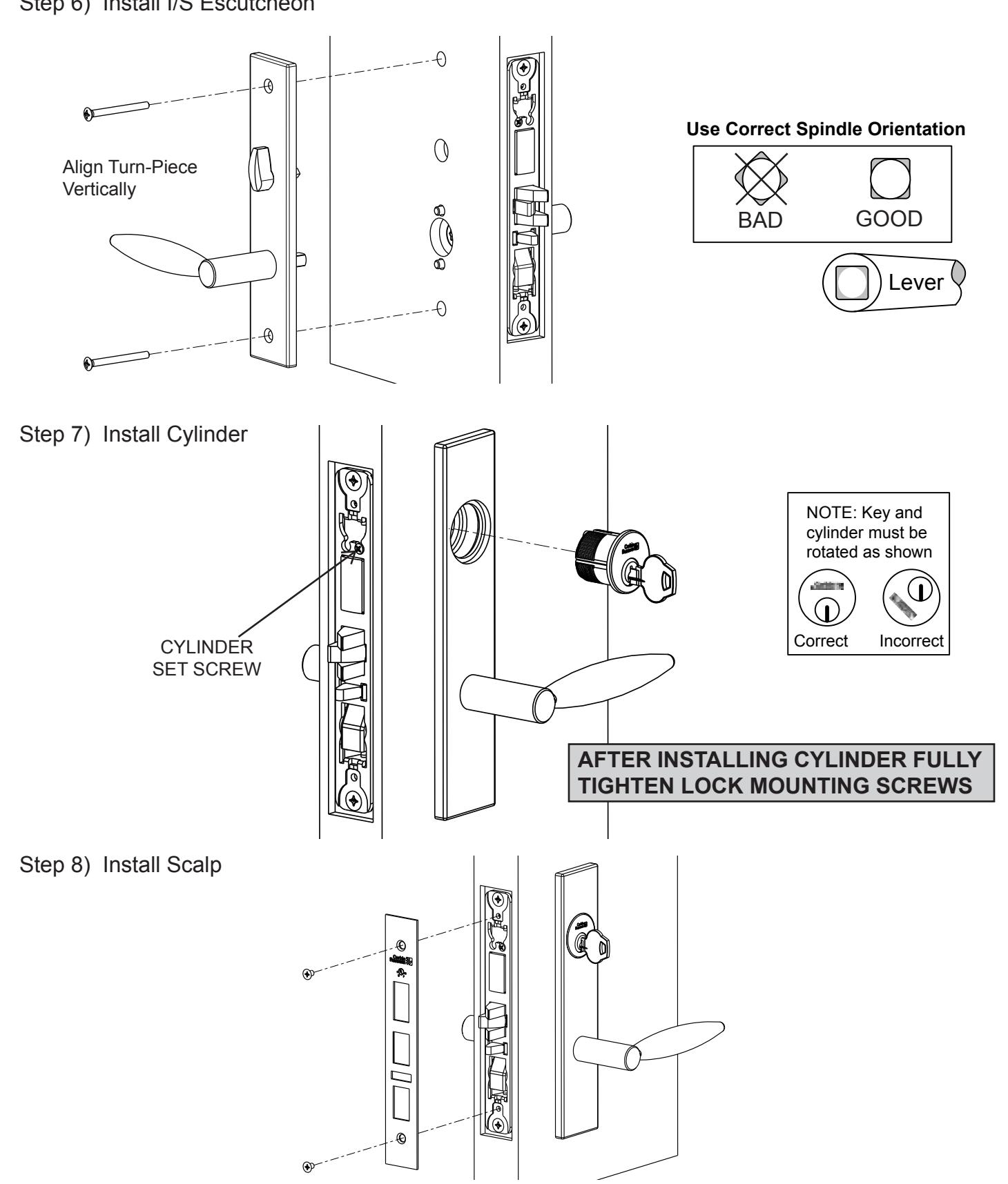
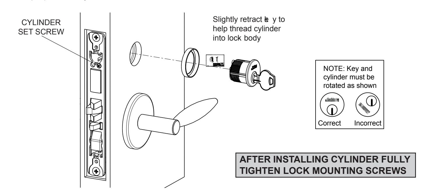
Step 9) Install cylinder and secure with set screw
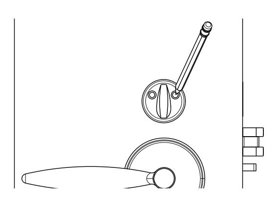
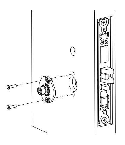
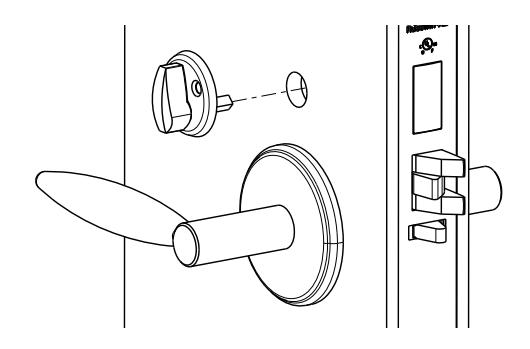
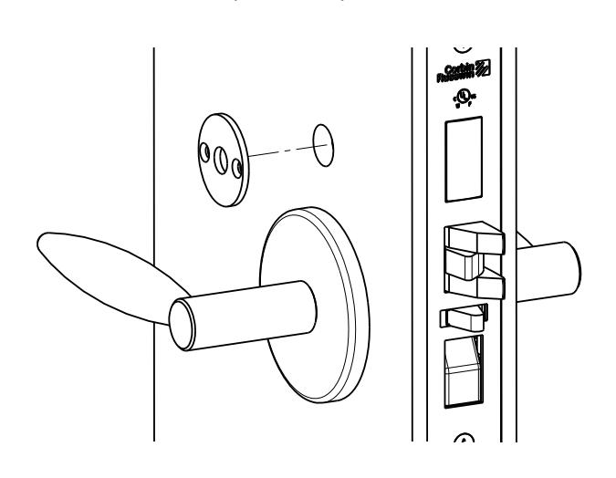
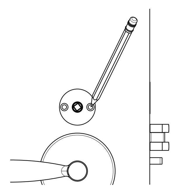
Step 10) Mark turn-piece mounting holes and drill two .110" ( BIT # 35) holes where marke d
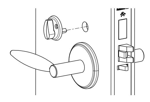
Step 11) M ount turn-piece
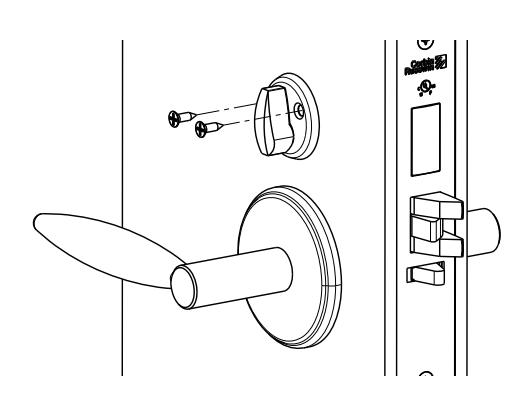
Step 12) Install scalp


R & L ESCUTCHEON:
Step 1) Install strike with shorter (3/4") mounting screws
Step 2) Insert mortise lock into door and hand tighten longer (1") mounting screws
Step 3) Thread hub into lever and fully tighten
Step 4) Align hub with square hole in lever; be eping hub as tight as possible
Step 5) Install O/S trim assembly
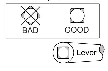
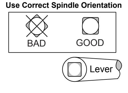
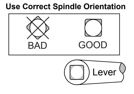
Use Correct Spindle Orientation
INSTALLATION INSTRUCTIONS

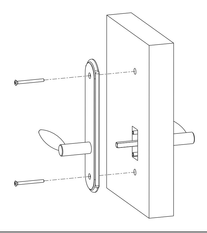
Step 6) Install I/S Escutcheon

HALF WORKING TRIM INSTALLATION
SECTIONAL:
Step 1) Install strike with shorter (3/4") mounting screws
Step 3) Install I/S adapter plate
Step 5) Install I/S lever with set screw
Step 2) Insert mortise lock into door and hand tighten longer (1") mounting screws
Step 4) Install spindle and rose

Step 6) Install cylinder and secure with set screw
Step 7) M ark turn-piece mounting holes and drill two .110" ( BIT # 35) holes where marke d
Step 8) M ount turn-piece Step 9) Install scalp


R & L ESCUTCHEON:
Step 1) Install strike with shorter (3/4") mounting screws
Step 3) Thread hub into lever and fully tighten
Step 5) Install I/S Escutcheon
Step 2) Insert mortise lock into door and hand tighten longer (1") mounting screws
Step 4) Align hub with square hole in lever; eping hub as tight as possible


Step 6) Install cylinder and secure with set screw
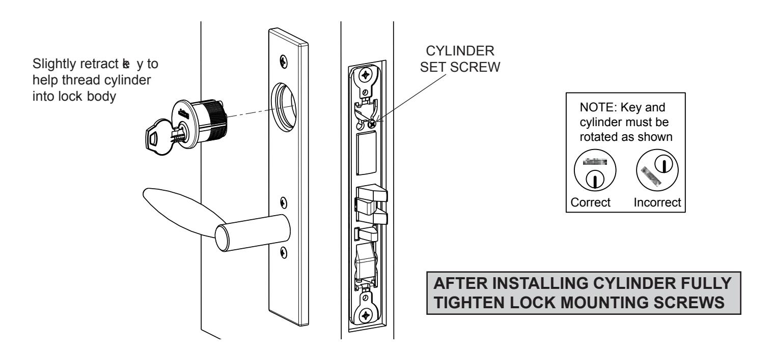
Step 7) Install scalp

FULL DUMMY TRIM IN STALLATION
SE CT ION AL:
Step 1) Install O/S adapter plate Step 2) Install I/S adapter plate
Step 3) Install rose onto both adapter plates

Step 4) Install both levers with set screw

R & L E SCU TCHEON :
Step 1) Insert spindle into hub and rotate lever CW until tight

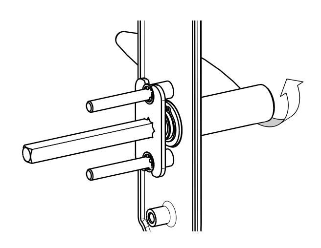
NOTE: Repeat step 1 & 2 for I/S Escutcheon
Step 3) Install O/ S Escutcheon Step 4) Install I/ S Escutcheon

HALF DUMMY TRIM IN STALLATION
SE CT ION AL:
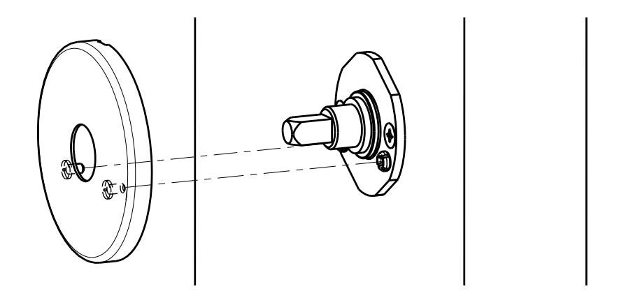
Step 1) Install adapter plate
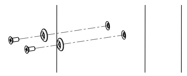
Step 2) Install mounting screws and washers
Step 3) Install rose onto adapter plate
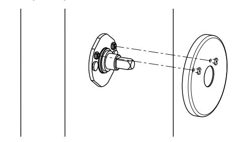
Align studs on rose with bushings in adapter plate
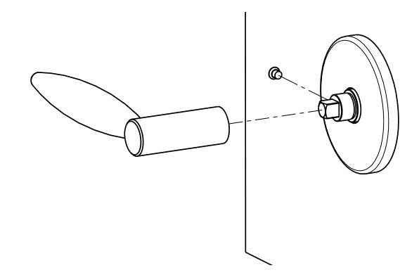
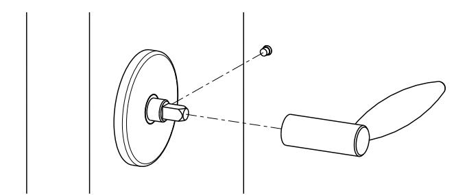
Step 4) Install lever with set screw

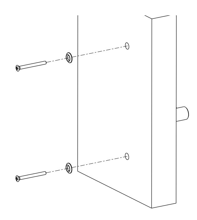
R & L E SCU TCHEON :
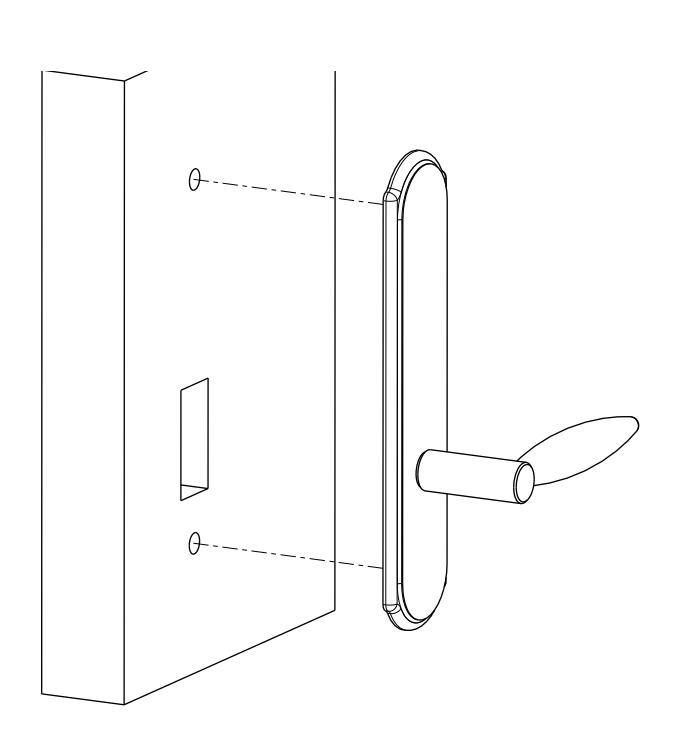
Step 1) H old O/S escutcheon on door Step 2) Install mounting screws and washers
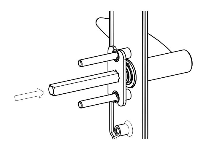
NOTE: Re-hand the lever, if necessary, by pushing spindle out of dummy plate and rotating lever

SE CON DARY TRIM IN STALLATION
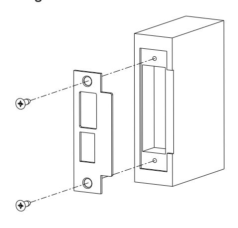
EMERGENCY KEY PLATE:
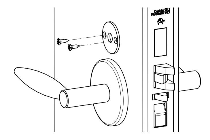
Step 1) M ark emergency ke y mounting holes and drill two .110" (BIT #35) holes where marke d
Step 2) M ount emergency ke y plate
In US: Corbin Russwin, Inc. 225 Episcopal Road Berlin, CT 06037-4004 www.corbinrusswin.com
Technical Product Support:
Phone: 888-607-5703 Fax: 800-659-7293
In Canada: ASSA ABLOY Door Security Solutions Canada 160 Four Valley Drive Vaughan, ON, L4K 4T9
www.assaabloy.ca


In U.S.: Corbin Russwin, Inc. 225 Episcopal Road Berlin, CT 06037 USA Phone: 800-543-3658
Technical Product Support:
Phone: 888-607-5703 In Canada: ASSA ABLOY Door Security Solutions Canada 160 Four Valley Drive Vaughan, Ontario, Canada L4K 4T9
Phone: 800-461-3007