Corbin Russwin Mortise Lock Inspire Roseless Trim Installation Instructions
Open the original PDF document
View PDF

MORTISE LOCK INSTALLATION INSTRUCTIONS
INSPIRETM ROSELESS DESIGNER TRIM
FM 340 Rev. 10/18


INSPIRE TM Mortise Trim Instructions FM 340 Rev. 10/18

TABLE OF CONTENTS:
| DOOR PREPARATION | 1 |
|---|---|
| ML2000 LOCK HANDING | 2 |
| FULL WORKING TRIM (STD) | 3 |
| HALF WORKING TRIM (M30) | 6 |
| FULL DUMMY TRIM (ML2070) | 8 |
| HALF DUMMY TRIM (ML2050) | 9 |
| CYLINDER / TURN-PIECE | 10 |
WARNING
This product can expose you to lead which is known to the state of California to cause cancer and birth defects or other reproductive harm. For more information go to www.P65warnings.ca.gov.
08/2018
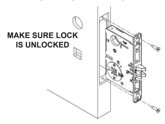
LOCK HANDING IS CRITICAL TO ENSURE LOCK FUNCTIONS PROPERLY
INSPIRETM Mortise Trim Instructions FM 340 Rev. 10/18

DOOR PREPARATION:
| TEMPLATE | |
|---|---|
| FULL WORKING TRIM: | T31183 |
| HALF WORKING TRIM: | T31184 |
| FULL DUMMY TRIM: | T31186 |
| HALF DUMMY TRIM: | T31187 |
ALL TEMPLATES CAN BE FOUND AT WWW.CORBINRUSSWIN.COM/Library/Templates
INSPIRETM Mortise Trim Instructions FM 340 Rev. 10/18

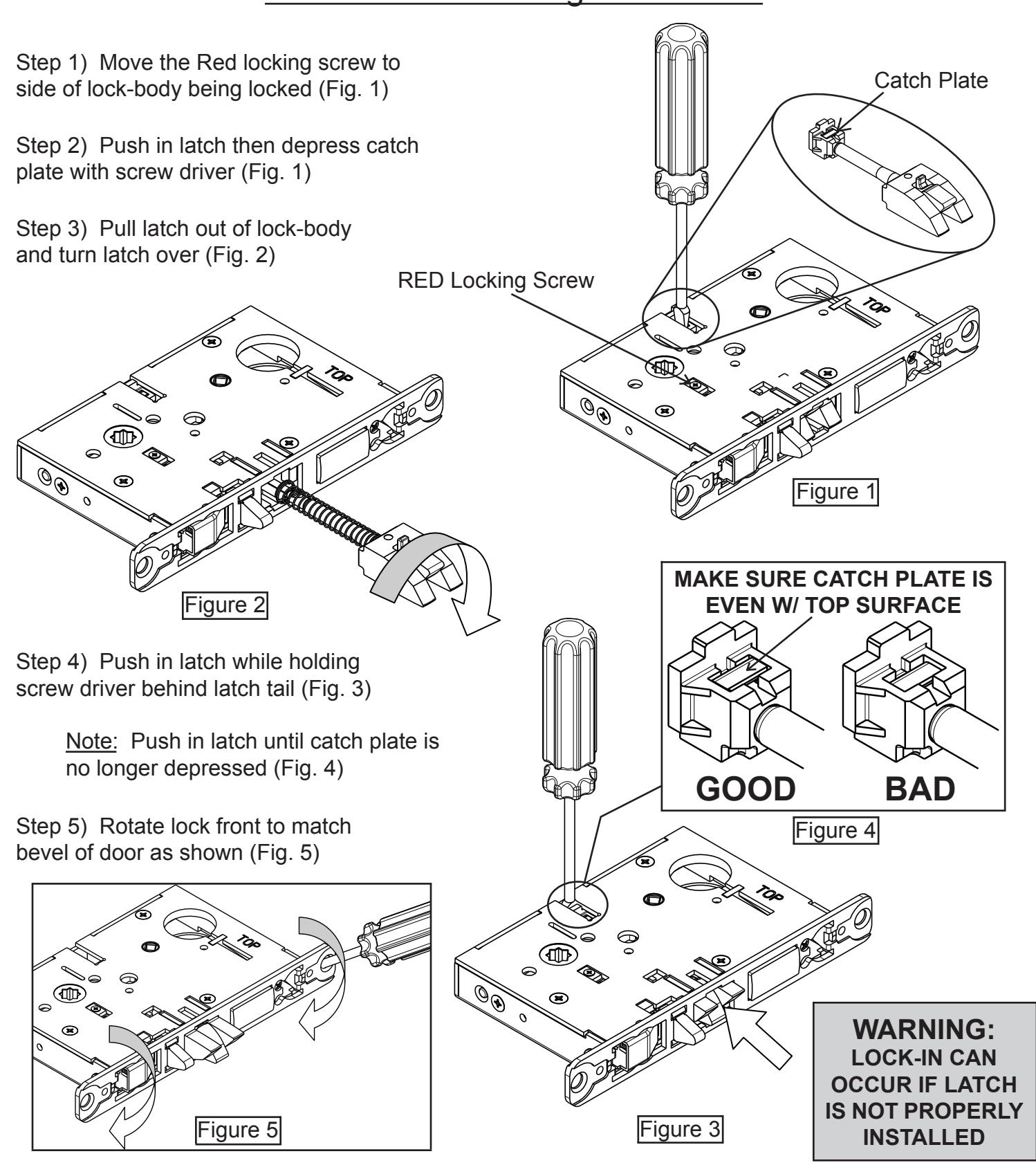
Mortise Lock Handing Instructions

FULL TRIM (STD) INSTALLATION
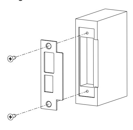
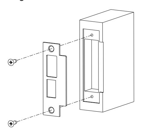
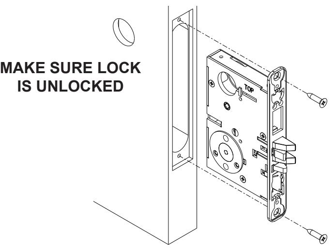
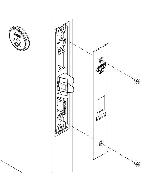
Step 1) Install strike with shorter 3/4" mounting screws
Step 2) Insert mortise lock into door and hand tighten longer 1" mounting screws
Step 3) Install spacer blocks on both sides of lock-body with 1/4" Fillister Head Screws
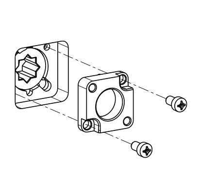
Note: Align tabs on spacer with cutouts on lock-body
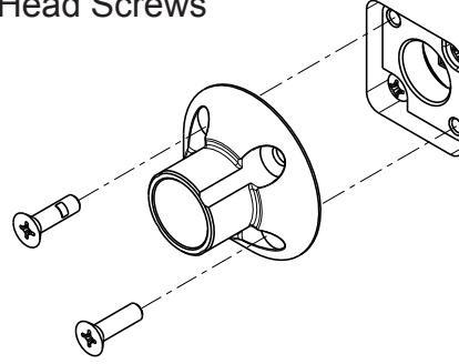
Step 4) Install adapter plates on both sides of door using 1/2" Flat Head Screws
INSPIRETM Mortise Trim Instructions FM 340 Rev. 10/18
Keypad ribbon cable
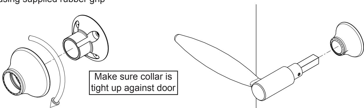
Step 5) Thread collar onto both sides of door using supplied rubber grip
Step 6) Install O/S Lever
Step 7) Install I/S spindle and adjustment bolt
Step 9) Rotate both levers individually and make sure both levers return. If either lever binds, remove I/S lever and un-thread adjustment bolt 1/2 turn.
INSPIRETM Mortise Trim Instructions FM 340 Rev. 10/18

Step 10) If the lock function calls for a cylinder or turn-piece proceed to cylinder and turn-piece instructions on page 10. Otherwise proceed to next step
Step 11) Install scalp using 3/16" Flat Head Screws

HALF TRIM (M30) INSTALLATION
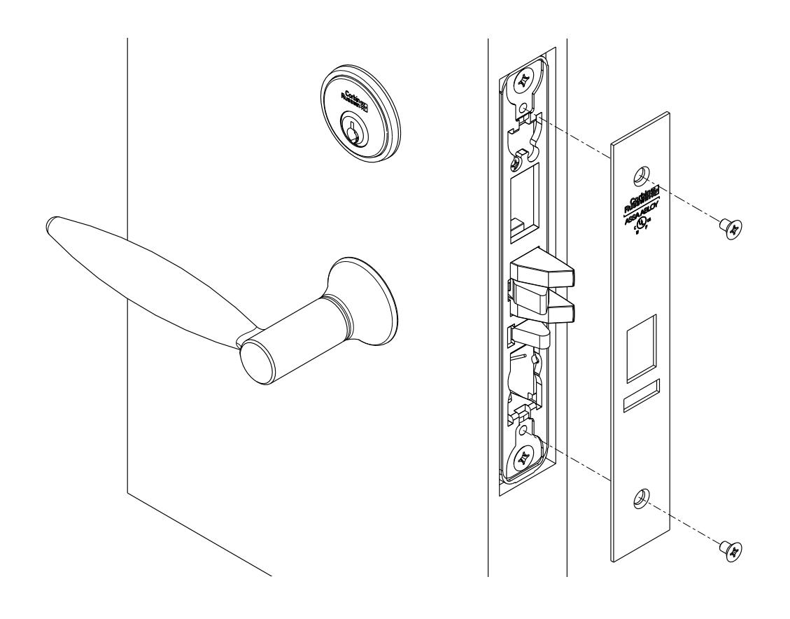
Step 1) Install strike with shorter (3/4") mounting screws
tighten longer (1") mounting screws
Step 2) Insert mortise lock into door and hand
Step 3) Install spacer block on trim side of
lock-body with 1/4" Fillister Head Screws
Align tabs on spacer with cutouts on lock-body
Step 4) Install adapter plate on trim side of door using 1/2" Flat Head Screws
Step 5) Thread collar on trim side of door using supplied rubber grip
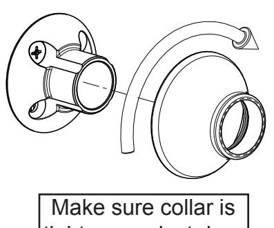
tight up against door
INSPIRETM Mortise Trim Instructions FM 340 Rev. 10/18
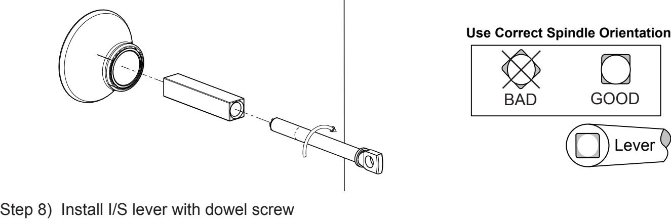
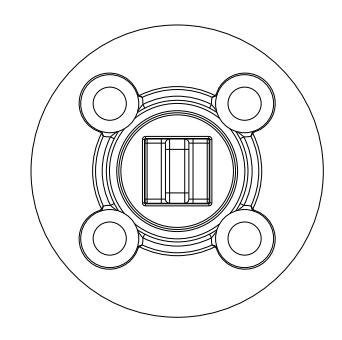
Step 6) Install I/S spindle and adjustment bolt
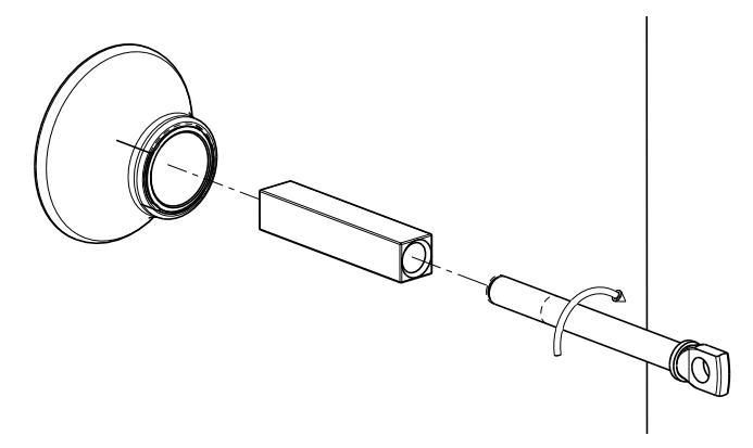
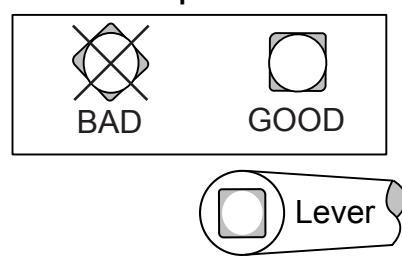
Use Correct Spindle Orientation
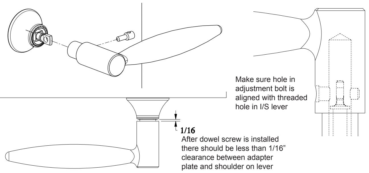
Step 7) Install I/S lever with dowel screw
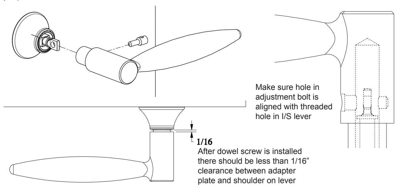
Step 8) Rotate both levers individually and make sure both levers return. If either lever binds, remove I/S lever and un-thread adjustment bolt 1/2 turn.
Step 10) If the lock function calls for a cylinder or turn-piece proceed to cylinder and turn-piece instructions on page 10. Otherwise proceed to next step
Step 11) Install scalp using 3/16" Flat Head Screws
INSPIRETM Mortise Trim Instructions FM 340 Rev. 10/18

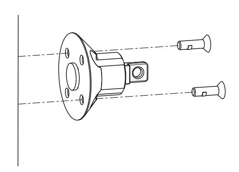
FULL DUMMY TRIM (ML2070) INSTALLATION
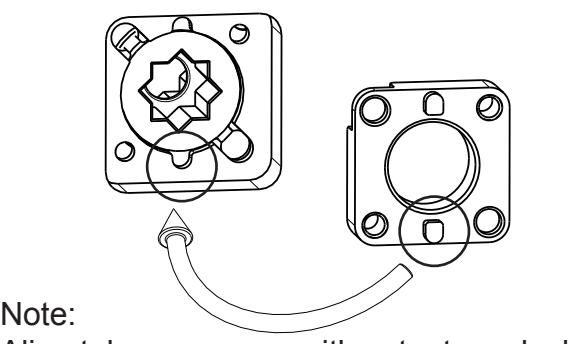
Step 1) Insert dummy spindle into both adapter plates
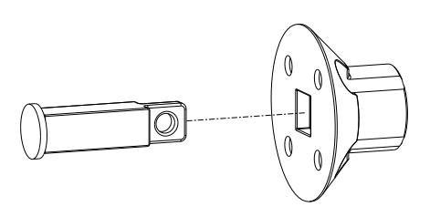
Make sure dummy spindle is aligned as shown
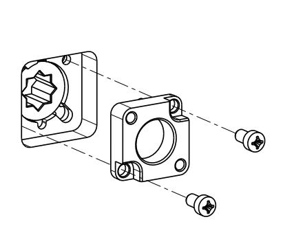
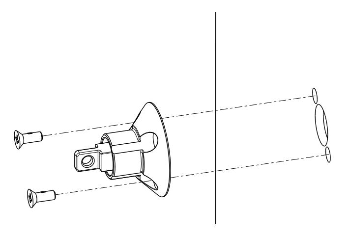
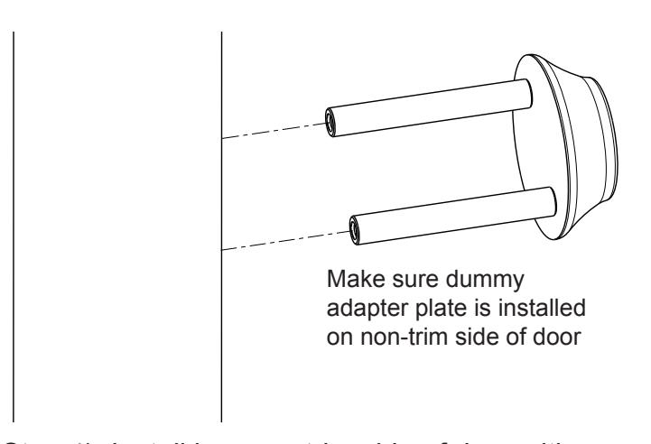
Step 2) Install adapter plate assemblies
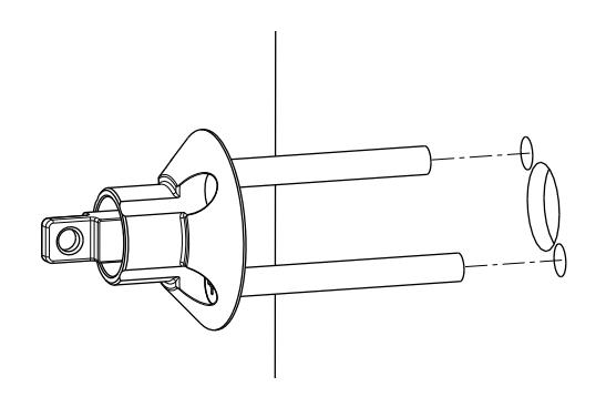
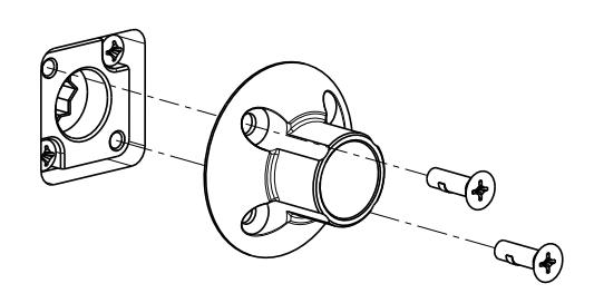
Step 3) Thread collar on both sides of door
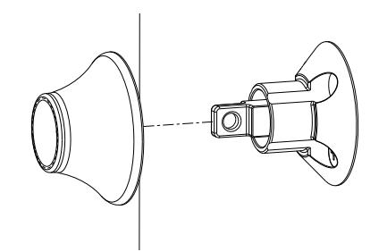
Make sure collar is tight up against door
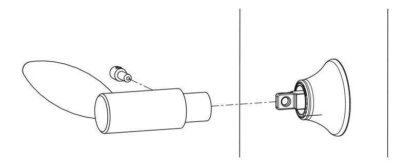
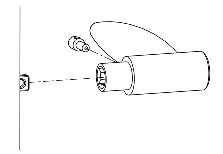
Step 4) Install lever on both sides of door with dowel screws

HALF DUMMY TRIM (ML2050) INSTALLATION
Step 1) Insert dummy spindle into adapter plate
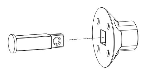
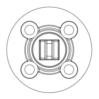
Make sure dummy spindle is aligned as shown
Step 2) Install adapter plate assemblies
Step 3) Thread collar on trim side of door Step 4) Install lever on trim side of door with dowel screw
Make sure collar is tight up against door
INSPIRE TM Mortise Trim Instructions FM 340 Rev. 10/18

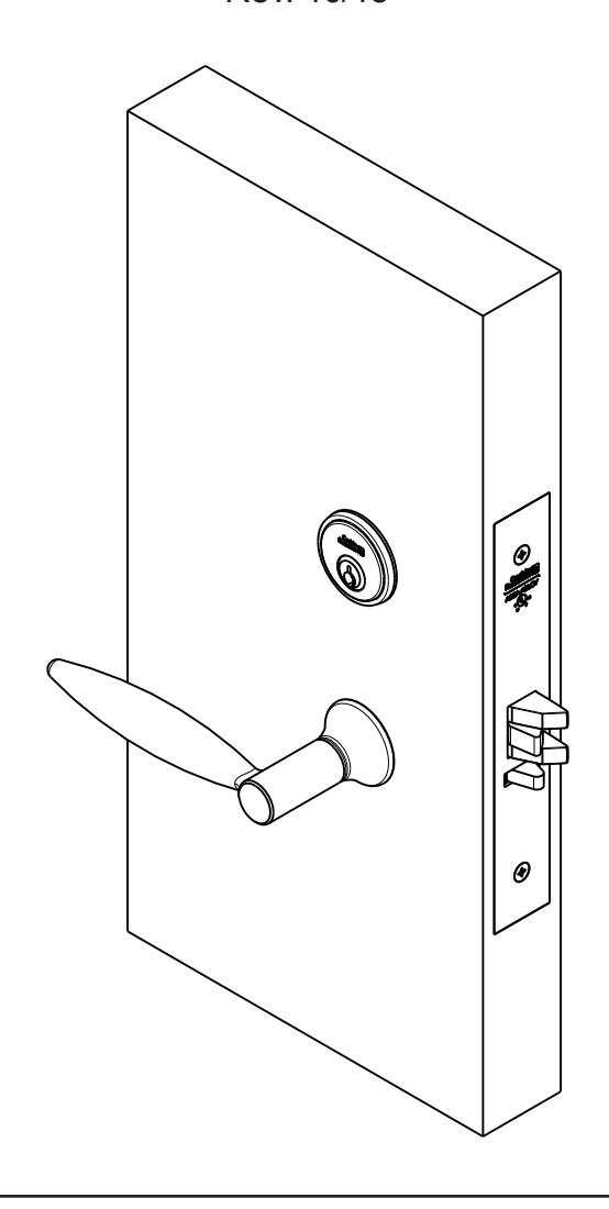
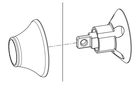
CYLINDER AND TURN-PIECE INSTALL
Cylinder Install:
- Push cylinder collar over cylinder then thread cylinder into lock-body
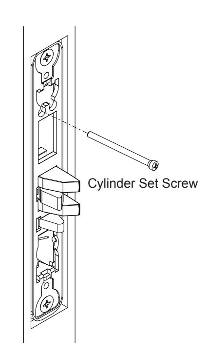
- Secure cylinder with set screw
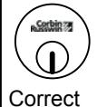
NOTE: Key and cylinder must be rotated as shown


- If cylinder will not thread into lock loosen lock mounting screws
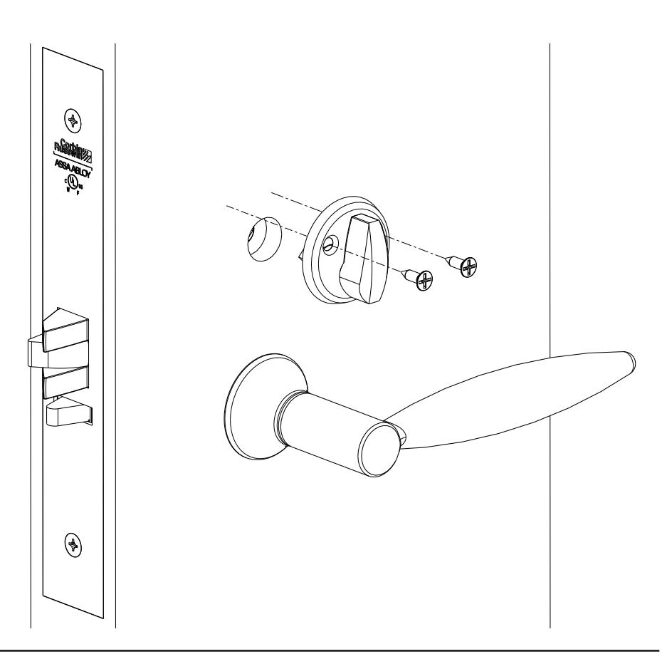
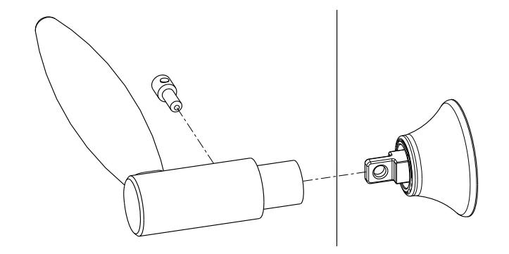
Turn-Piece Install:
- Mark turn-piece mounting holes then drill two .110" holes where marked
- Make sure turn-piece is vertical when lock is unlocked