Corbin Russwin MP9800 Series Multi-Point Lock Installation Instructions
Open the original PDF document
View PDFMP9800 Series Multi-Point Lock Installation Instructions
® ASSA ABLOY ®
with MELR Option (Electric Latch Retraction) MP9800 Series Multi-Point Lock with MELR Option (Electric Latch Retraction)

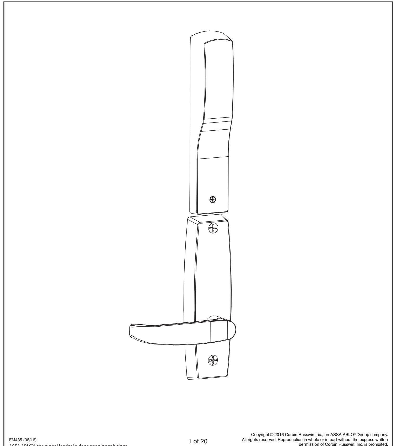
with MELR Option (Electric Latch Retraction)

Table of Contents
| 1 | Warnings | 2 |
|---|---|---|
| 2 | General Description3 | |
| 3 | Hardware Specifications | 3 |
| 4 | Electronic Specifications | 3 |
| 5 | Parts Breakdown | 4 |
| 6 | Installation Instructions5-8 | |
| 7 | Wiring Diagrams9-10 | |
| 8 |
Mechanical Operational Check
10 |
|
| 9 |
Electrical Operational Check
11-18 |
1 Warnings

Changes or modifications to this unit could void the user's authority to operate the equipment. ALWAYS disconnect power before making any electrical or mechanical adjustments to the system. Observe precautions for handling electrostatic sensitive devices.
This device complies with Part 15 of the FCC Rules. Operation is subject to the following two conditions:
- (1) This device may not cause harmful interference, and
- (2) This device must accept any interference received, including interference that may cause undesired operation.

Note: This equipment has been tested and found to comply with the limits for a Class B digital device, pursuant to Part 15 of the FCC Rules. These limits are designed to provide reasonable protection against harmful interference in a residential installation.
This equipment generates, uses and can radiate radio frequency energy and if not installed and used in accordance with the instructions, may cause harmful interference to radio communications. However, there is no guarantee that the interference will not occur in a particular installation. If this equipment does cause harmful interference to radio or television reception, which can be determined by turning the equipment off and on, the user is encouraged to try to correct the interference by one or more of the following measures:
- Reorient or relocate the receiving antenna
- Increase the separation between the equipment and receiver
- Connect the equipment into an outlet on a circuit different from that to which the receiver is connected
- Consult the dealer or an experienced TV technician for help
This Class B digital apparatus complies with Canadian ICES-003.
Cet appareil numérique de la classe B est conforme avec la norme NMB-003 du Canada.
The term "IC:" before the radio certification number only signifies that Industry Canada technical specifications were met. This Class B digital apparatus meets all requirements of the Canadian Interference Causing Equipment Regulations.
Cet appareillage numérique de la classe B répond à toutes les exigences de l'interférence canadienne causant des règlements d'équipement. L'opération est sujette aux deux conditions suivantes:
- (1) ce dispositif peut ne pas causer l'interférence nocive, et
- (2) ce dispositif doit accepter n'importe quelle interférence reçue, y compris l'interférence qui peut causer l'opération peu désirée.

Important: Any retroit or other field modification to a fire rated opening can potentially impact the fire rating of the opening, and Corbin Russwin Inc. makes no representations or warranties concerning what such impact may be in any specific situation. When retrofitting any portion of an existing fire rated opening, or specifying and installing a new fire-rated opening, please consult with a code specialist or local code official (authority having jurisdiction) to ensure compliance with all applicable codes and ratings
with MELR Option (Electric Latch Retraction)

2 General Description
The Corbin Russwin stand alone MP9800 x MELR series multi point lock is designed to automatically retract the rods, concealed within the door.
1. Functions
The MP9800 x MELR can be configured to work in either of two modes:
POWER MODE (see Section 9: Electrical Operation, Section I: POWER MODE)
The device is not energized when locked. When electrified, the device will retract and remain in the retracted position until power is removed. Power is typically applied through a relay triggered by an access control device.
TIMER MODE (see Section 9: Electrical Operation, Section II: TIMER MODE)
The device is always energized and retraction is triggered by a momentary or maintain switch.
In TIMER MODE:
When the timer circuit is closed using a momentary switch, the device retracts, remains retracted for a set duration, and releases. The duration of the retraction is set through an onboard timer setting.When the timer circuit is closed using a maintain switch, the device retracts. The device releases when the contact is opened.

2. Important:
Caution: Disconnect all input power before servicing. Installer must be a trained and experienced service person. Wiring must comply with applicable local electrical codes, ordinances and regulations.
3. Installation Notes
Earth Ground: Required for electrostatic discharge (ESD) protection, unless already grounded through the metal door and frame.
Tools Required - (Same for all Series Products)
- Phillips screw driver
- Drill with bits
- Slotted screw driver
- #8-32 tap & drill (for metal door applications)
3 Hardware Specifications 4 Electronic Specifications
All Access 600 Multi Point Locks
- Fire rated devices available
- UL and CUL listed for use on Fire Doors
- Multi point lock furnished for 1-3/4" doors
- Wire from EAC Panel to door must be shielded with a drain terminated at EAC Panel controller
12VDC System
• 12VDC MELR Draw= 850mA
24VDC System
• 24VDC MELR Draw = 700mA

Wire Gauge Charts
|
Total
One-Way |
Load Current @ 12VDC | |||||||
|---|---|---|---|---|---|---|---|---|
|
Length of
Wire Run (ft) |
1/4A | 1/2A | 3/4A | 1A | 1-1/4A | 1-1/2A | 2A | 3A |
| 100 | 20 | 18 | 16 | 14 | 14 | 12 | 12 | 10 |
| 150 | 18 | 16 | 14 | 12 | 12 | 12 | 10 | — |
| 200 | 16 | 14 | 12 | 12 | 10 | 10 | — | — |
| 250 | 16 | 14 | 12 | 10 | 10 | 10 | — | — |
| 300 | 16 | 12 | 12 | 10 | 10 | — | — | — |
| 400 | 14 | 12 | 10 | — | — | — | — | — |
| 500 | 14 | 10 | 10 | — | — | — | — | — |
| 750 | 12 | 10 | — | — | — | — | — | — |
| 1,000 | 10 | — | — | — | — | — | — | — |
| 1,500 | 10 | — | — | — | — | — | — | — |
|
Total
One-Way |
Load Current @ 24VDC | |||||||
|---|---|---|---|---|---|---|---|---|
|
Length of
Wire Run (ft) |
1/4A | 1/2A | 3/4A | 1A | 1-1/4A | 1-1/2A | 2A | 3A |
| 100 | 24 | 20 | 18 | 18 | 16 | 16 | 14 | 12 |
| 150 | 22 | 18 | 16 | 16 | 14 | 14 | 12 | 10 |
| 200 | 20 | 18 | 16 | 14 | 14 | 12 | 12 | 10 |
| 250 | 18 | 16 | 14 | 14 | 12 | 12 | 12 | 10 |
| 300 | 18 | 16 | 14 | 12 | 12 | 12 | 10 | — |
| 400 | 18 | 14 | 12 | 12 | 10 | 10 | — | — |
| 500 | 16 | 14 | 12 | 10 | 10 | — | — | — |
| 750 | 14 | 12 | 10 | 10 | — | — | — | — |
| 1,000 | 14 | 10 | 10 | — | — | — | — | — |
| 1,500 | 12 | 10 | — | — | — | — | — | — |
with MELR Option (Electric Latch Retraction)

5 Parts Breakdown
MP9800 x MELR Series
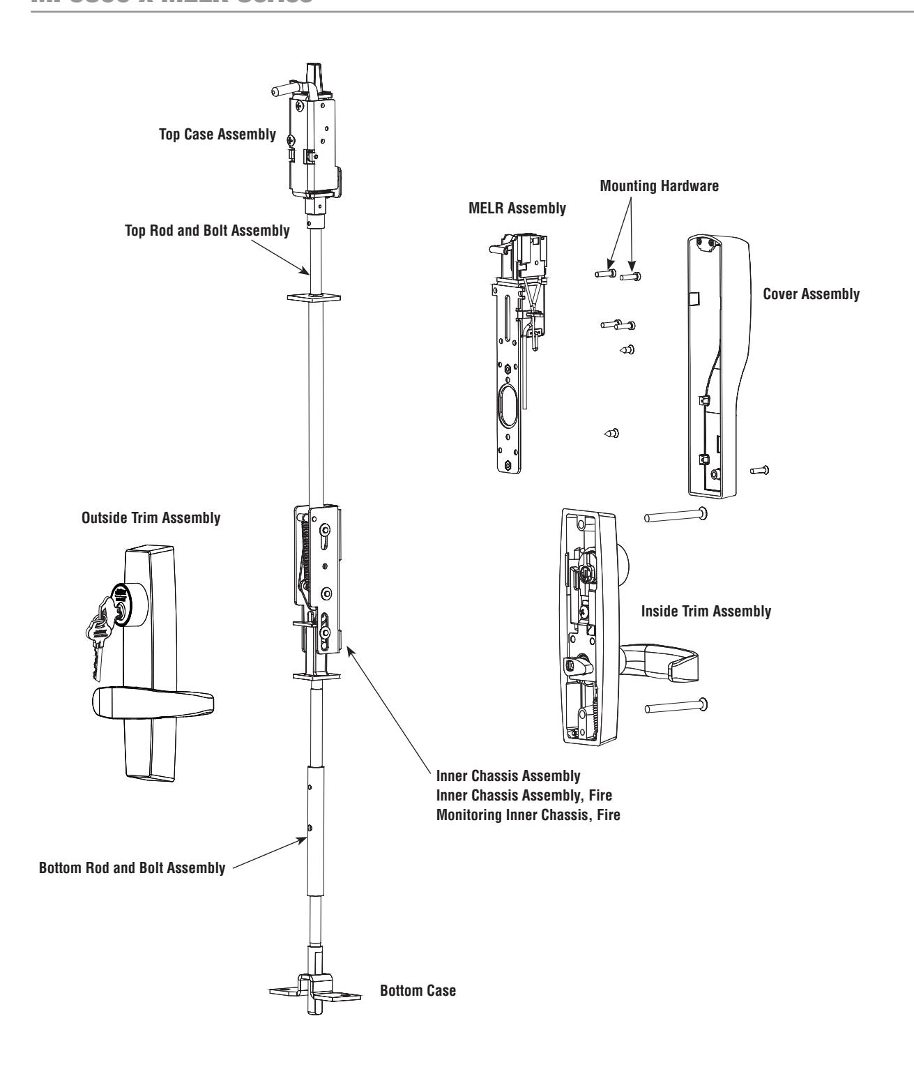
with MELR Option (Electric Latch Retraction)

6 Installation Instructions
A) Door Preparation
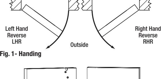
1. Verify Hand and Bevel of Door -(Figure 1)
- Check hand of door. The Multi-Point lock may be handed.
- Door should be fitted and hung.
- Verify box label for size of the Multi-Point lock, function and hand.
- Change hand if necessary.
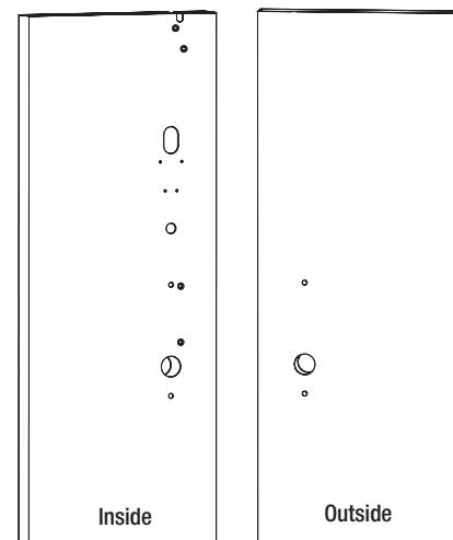
2. Door Preparation
If door is not pre-drilled, prepare door according to the appropriate template. Refer to templates at www.corbinrusswin.com. (Figure 2).
• Metal door (Steel & MPAD): FM438
- Templates: T31242
• Wood door (MPWD): FM436
- Templates: T31243
Inside

B) Rod and Top Case Installation
- 1. Refer to instruction sheet FM438 for rod and inner case installation on metal doors.
- 2. Refer to instruction sheet FM436 for rod and inner case installation on wood doors. (Figure 3).
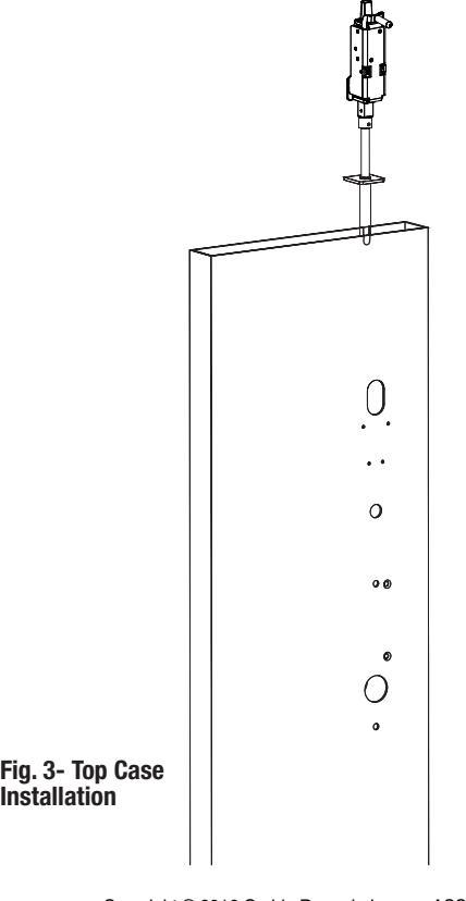
Installation
with MELR Option (Electric Latch Retraction)

6 Installation Instructions - con't
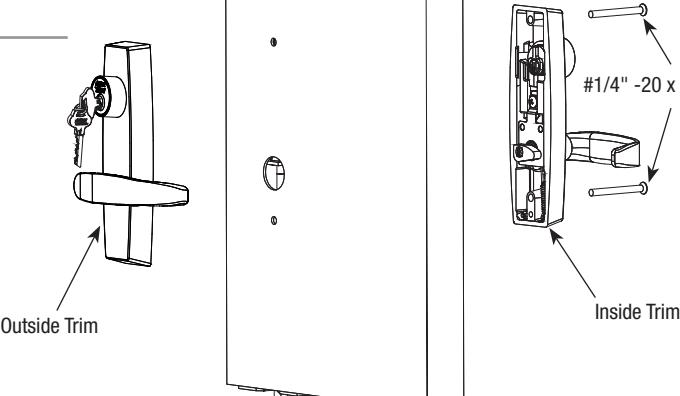
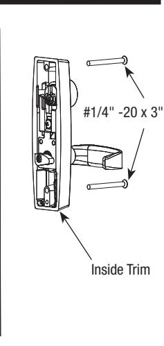
C) Install Outside and Inside Trim
Install Trim
- 1. Mount inside trim lever to outside trim lever using (2) # 1/4" -20 x 3" Phillips oval head machine screws. (Figure 4).
- 2. Feed wire through the through hole and attach the outside exit trim to the door.
Wire Hole
Fig. 5a
Mark Vertical Centerline
Fig. 4
Centerline
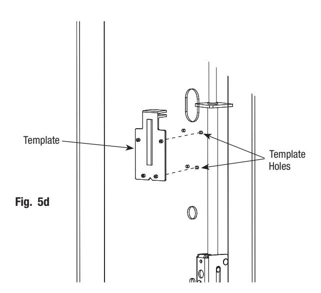
D) Preparation of MELR Mounting Holes (If Required)

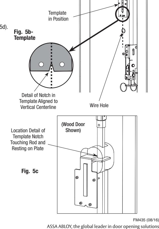
Important: If the manufacturer has not pre-drilled the door, prepare the door per instructions below, using plastic template included with the device. Screw hole orientation is not affected by handing. (See Figures 5a-5d). If the door is pre-drilled by the manufacturer, continue to instructions on the following page.
- 1. Mark vertical centerline of slot and wire hole on door. (See Figure 5a).
- 2. Mount template onto plate as shown. For wood doors, ensure the template notch is touching the rod to provide lateral positioning. (See Figure 5c).
- 3. Check that template is square to door. (See Figure 5b).
- 4. Using template bushings as a guide, drill (4) 1/16" holes. (See Figure 5d).
- 5. Remove template.
- 6. For metal door, increase 1/16" pilot holes to #29 (.136) and tap for #8-32.
Copyright © 2016 Corbin Russwin Inc., an ASSA ABLOY Group company. All rights reserved. Reproduction in whole or in part without the express written permission of Corbin Russwin, Inc. is prohibited.
with MELR Option (Electric Latch Retraction)

6 Installation Instructions - con't
E) Installation of MELR Assembly
1. Install the upper left mounting screw, #8 - 32 x 5/8" Fillister head for metal door and #8 x 5/8" self tapping wood screw for wood doors. (See Figure 6a).

Note: Leave the screw loose enough to slide the MELR assembly on.
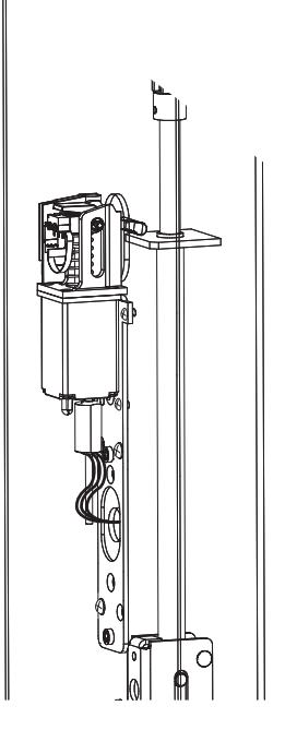
- 2. Snake the wire through the MELR assembly.
- 3. Slide the mounting bracket of the MELR assembly underneath the installed screw and secure in place.

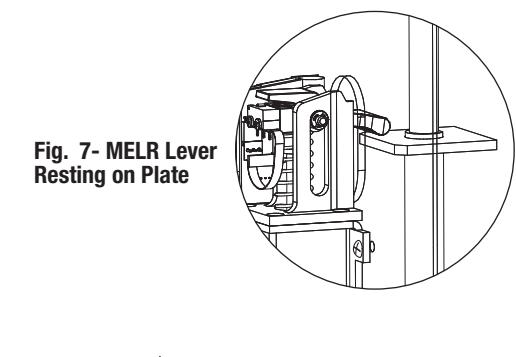
IMPORTANT: Ensure MELR retraction lever is resting on plate. (Fig. 7).
4. Completely tighten the upper left mounting screw.

IMPORTANT: Be careful not to pinch or disconnect the wires located in that area.
- 5a. Install the remaining (3) #8-32 x 5/8" Fillister mounting screws on metal doors. (See Figure 6b.)
- 5b. Install the remaining (3) #8 x 5/8" self tapping wood screws on wood doors. (See Figure 6b.)
- 6. Install (2) 1/4"self-tapping screws on either diagonal, one above molex connector and one below. (Figure 8).
- 7. Connect the 8-pin molex connectors.


1/4" Self-Tapping Screw

#8 - 32 x 5/8" Fillister Head Machine Screw
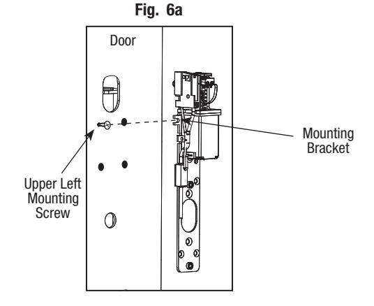
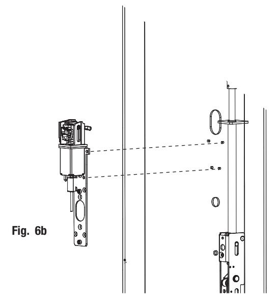
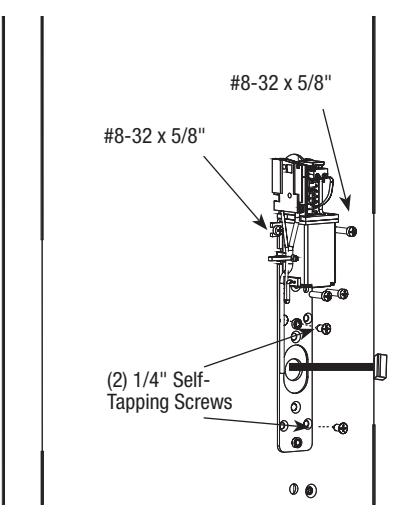
Fig. 8
with MELR Option (Electric Latch Retraction)

6 Installation Instructions - con't
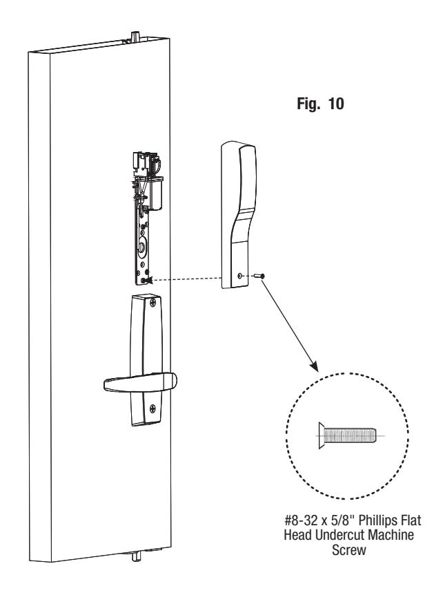
F) Installation of Inside Escutcheon
- 1. Position escutcheon against door by hooking the top edge on the top of the MELR assembly. Again, verify that no wires are being pinched.
- 2. Mount inside escutcheon assembly to plate using (1) #8-32 x 5/8" Phillips lat head undercut machine screw. (Figure 10).

with MELR Option (Electric Latch Retraction)


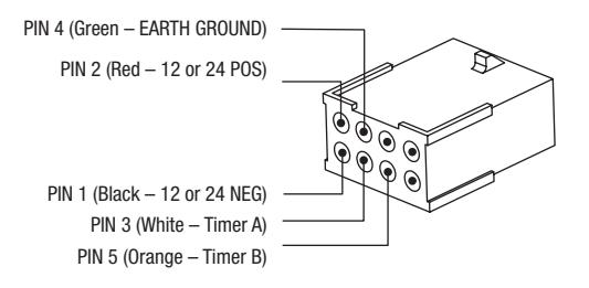
7 Wiring Diagrams
| Product | 8 PIN CONNECTOR | |||||
|---|---|---|---|---|---|---|
|
1-Black
2-Red 3-White 4-Green 5-Orange |
||||||
|
ACCESS CONTROL DEVICES: MP9800 x MELR ElectroLynx Wire
Color / Function Assignments |
||||||
|
Corbin Russwin
MP9800 xMELR |
NEG | POS | Timer A | EGND | Timer B | |
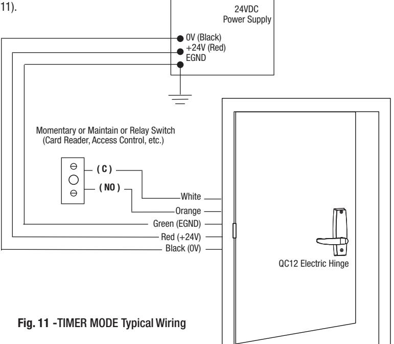
A) Timer Mode: Typical Wiring
- 1. For use when wiring in TIMER MODE (using the onboard timer).
- 2. If more than 20 seconds timed delay is necessary, an external timer delay relay is required (not provided). (Figure 11).

Note: 24V supply is constant in TIMER MODE.
with MELR Option (Electric Latch Retraction)

7 Wiring Diagrams - con't
B) Power Mode: Typical Wiring
For use when wiring in POWER MODE. (Figure 12).
Notes:
- Onboard timer will not function in POWER MODE. Add external time delay if necessary.
- The switch is wired between the power supply and the load. Do not cycle the power supply.
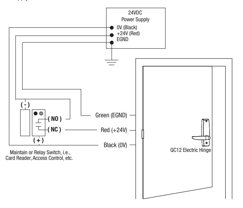
Fig. 12- Power Mode Typical Wiring
8 Mechanical Operational Check
For devices without cylinders, go to Section 6, Step C.
- 1. For devices with cylinders, insert key into cylinder and rotate.
- 2. Rotate the lever to retract latch and rods.
with MELR Option (Electric Latch Retraction)

9 Electrical Operational Check
SECTION I: POWER MODE
In this configuration, the device is not energized when locked. When energized with a 12 or 24 volt input, the latch(es) will retract and remain in the retracted position until power is removed. Power is typically applied through a relay triggered by an access control device. (Figures 13-15).
For installations using the onboard timer circuit, refer to SECTION II: TIMER MODE.
1) POWER MODE Installation Instructions
How it works: The MELR module retracts when power is applied and releases when power is removed.
1. Mount MP9800 x MELR Multi-point device using instruction sheet(s) provided.
Note: Ensure proper mechanical function before attempting electrical retraction:
- Verify the levers can be full rotated and the latch is fully retracted.
- Adjust device mechanically, as required, before applying power.
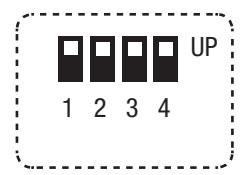
Fig. 13- Power Mode Settings
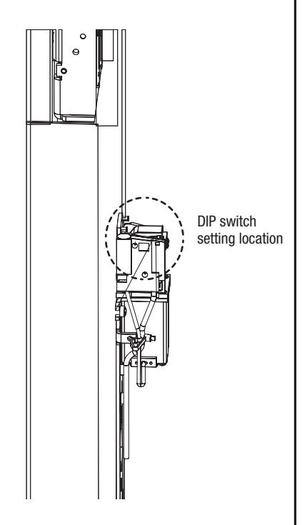
Fig. 14- Settings Location
- 2. Connect the ElectroLynx harness in the door (Figure 15,POWER MODE Installation): Plug the 8-pin ElectroLynx connector from the MELR into the ElectroLynx harness or splice into non-ElectroLynx harness.
- 3. Ensure all four DIP switches are in the UP position. (This enables POWER MODE).
- 4. Connect the ElectroLynx harness to the hinge and secure the electric hinge to door. Note: Make sure no wires are pinched or damaged in the process. Refer to detailed wiring instructions under POWER MODE wiring.
- 5. Apply 12V or 24V according to MELR input requirements (on next page): Confirm that the LED is blinking, that the system fully unlocks, and that all bolts clear the strikes.Troubleshoot the device if issues are observed using the steps outlined at the end of the POWER MODE section.
- 6. Store excess wiring under cover and assemble with provided screws. Avoid pinching wires.


9 Electrical Operational Check - con't
2) MELR- Input Requirements
Voltage: 24VDC
- Filtered and regulated power supply
- Motor operating current: 700mA
- Motor hold current: 150mA
Voltage: 12VDC
- Filtered and regulated power supply
- Motor operating current: 850mA
- Motor hold current: 250mA
Note: Earth Ground is required for Electrostatic Discharge (ESD) protection unless the metal door and frame are already earth grounded; otherwise, earth ground wiring is required at pin 4 (See Figures 13-15- POWER MODE Installation).
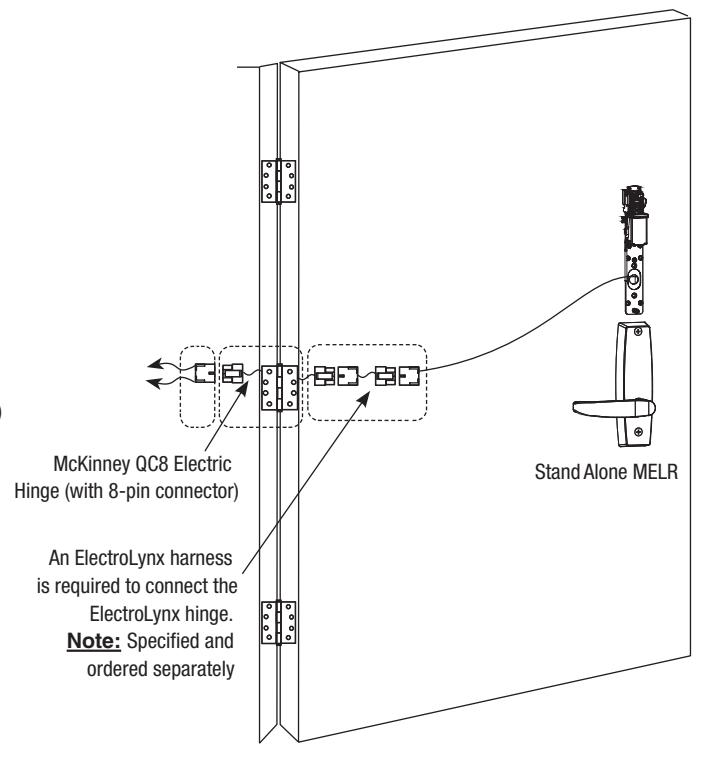
Fig. 15- POWER MODE Installation
3) LED Signaling Chart
| SIGNAL | CAUSE | TROUBLESHOOTING |
|---|---|---|
| Dark / Unlit |
Controller microprocessor
is not active |
Confirm connections and incoming
power |
| Steady Flashing (GREEN) | Normal operation | Check that POWER MODE switch is set |
| Solid Light (GREEN) |
Input voltage is dropping out of
operating range |
Check wire run and power supply output |
| 1 Flashes Followed by Pause (YELLOW) | Retractor sensor problem | Call 800-810-WIRE for assistance |
| 2 Flashes Followed by Pause (YELLOW) | Retractor sensor problem | Call 800-810-WIRE for assistance |
| 3 Flashes Followed by Pause (YELLOW) | Retractor sensor problem | Call 800-810-WIRE for assistance |

9 Electrical Operational Check - con't
4) POWER MODE Troubleshooting
Prior to electrical troubleshooting, confirm that the mechanical system properly functions; i.e., that the levers fully retract all latches and rods, and the door opens freely. Refer to applicable Corbin Russwin MP9800 Series Multi-point Device product instruction sheet to correct mechanical installation issues.

IMPORTANT: *ALWAYS disconnect power before making any mechanical adjustments to the system.
The MELR module does not move when 24V/12V input is applied:
- o Check inputs to confirm proper voltage and wiring orientation.
- o Remove cover and confirm that LED is blinking steadily when power is applied. If not, refer to LED signaling.
Note: When configured in POWER MODE, power is released to lock the device (LED will not blink when power is released).
o Confirm all four DIP switches are in the UP position.
The MELR module does not fully retract or MELR module retracts completely and holds but does not open door
- o *Verify mechanical installation and correct as necessary:
- Is excessive force required to rotate lever?
- Are latches fully clearing the strikes when mechanically cycled?
The MELR module retracts and unlocks electrically but does not relock:
- o Physically disconnect power from MELR and confirm that input is off.
- o *Check for mechanical interference (e.g., warped door, lack of shims, misalignment of MELR, etc.).
The MELR module behaves abnormally (multiple cycles, clicking, delayed retraction, etc.):
o Remove cover and confirm that LED is blinking steadily when power is applied. If not, refer to LED signaling. Note: When configured in POWER MODE, power is released to lock the device (LED will not blink when power is released).
For applications using automatic operator(s): Door(s) fail to unlock before doors begin to open:
o Adjust timing of operator to allow 750ms for the MELR module to fully retract.
For additional installation assistance, please contact 1-800-810-WIRE (9473). When calling, please provide the following information to improve our service (provide what you can):
- o Your name and contact number.
- o Corbin Russwin MP9800 Multi-point Device product type.
- o Location and identification of the affected opening (e.g., site, building, and door number).
- o Corbin Russwin order number (located on product box), if available.
- o Power supply manufacturer and rated output (i.e., voltage and current).
- o Method of operation (e.g.,POWER MODE).
- o The number of devices connected to the power supply.
- o Symptoms of problem (i.e., observed behavior).

9 Electrical Operational Check - con't
SECTION II: TIMER MODE
In this configuration, the device is always energized with a 24 or 12 volt input, and a timer circuit is opened or closed to control rod retraction. A momentary or maintain switch is typically used to perform this operation.
For installations where the power input is cycled to retract the device, refer to SECTION I: POWER MODE.
When TIMER MODE is used in conjunction with an external device, such as a door operator, a keypad/reader with two relays are required. Otherwise, an external relay board is required.
1) POWER MODE Installation Instructions
How it works:The MELR module retracts when timer input circuit is closed.
1. Mount MP9800 x MELR Multi-point device using instruction sheet(s) provided.
Note: Ensure proper mechanical function before attempting electrical retraction:
- Verify the levers can be full rotated and the latch is fully retracted.
- Adjust device mechanically, as required, before applying power.
- 2. Ensure DIP switch (position 1) disables POWER MODE. Set to DOWN to disable.
- 3. Connect the ElectroLynx harness in the door (Figure 16- ElectroLynx TIMER MODE Wiring): Plug the 8-pin ElectroLynx connectors from the device into the ElectroLynx harness or splice into a non-ElectroLynx Harness (Figure 16- TIMER MODE Installation-next page).
- 4. Connect the ElectroLynx harness to the hinge:
- a. Plug the door harness's 8-pin connector into the hinge's ElectroLynx connector.
- b. Secure the electric hinge to door.
Notes: Make sure no wires are pinched or damaged in the process.
Refer to detailed wiring instructions under TIMER MODE wiring.
5. Apply 24V/12V according to MELR- input requirements:
Confirm that the LED is blinking and close the timer input circuit to retract the device. When the system retracts electrically, confirm that it fully unlocks and that all bolts clear the strikes. Troubleshoot the device if issues are observed using the steps outlined at the end of the TIMER MODE section.
6. Store excess wiring under cover and assemble with provided screws. Avoid pinching wires.
with MELR Option (Electric Latch Retraction)

9 Electrical Operational Check - con't
2) MELR- Input Requirements
Voltage: 24VDC
- · Filtered and regulated power supply
- Motor operating current: 700mA
- . Motor hold current: 150mA
Voltage: 12VDC
- · Filtered and regulated power supply
- Motor operating current: 850mA
- Motor hold current: 250mA
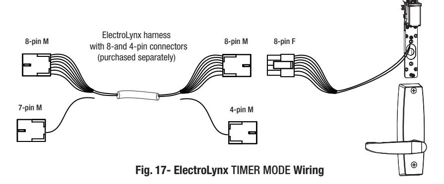
Note: Earth Ground is required for Electrostatic Discharge (ESD) protection unless the metal door and frame are already earth grounded; otherwise, earth ground wiring is required at pin 4 (See Figure 17- EletroLynx TIMER MODE Wiring).
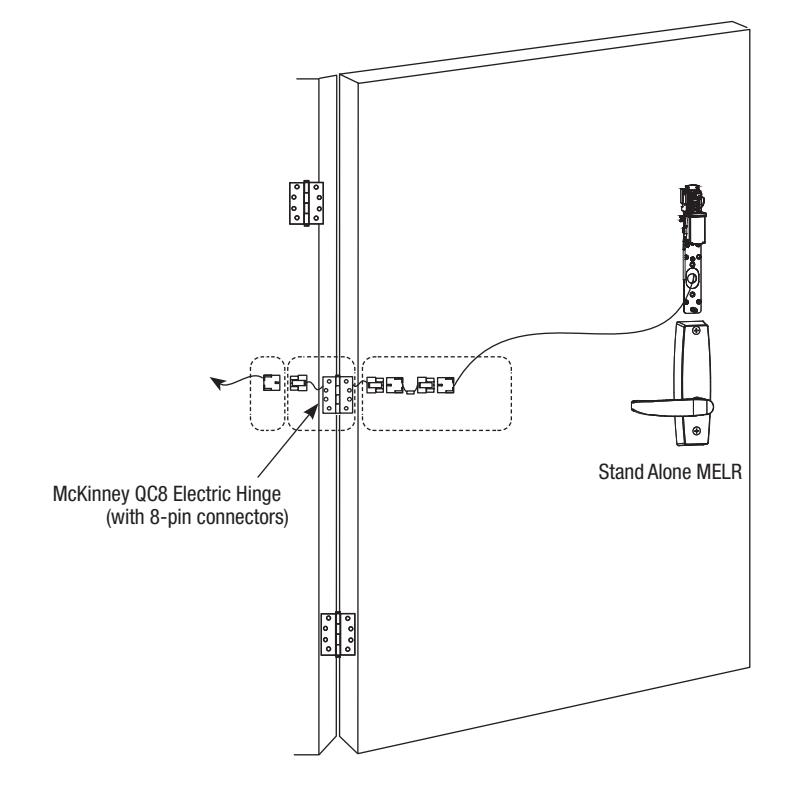
Fig. 16- TIMER MODE Installation
1 - Black (MELR OVDC)-2 - Red (MELR +24VDG) 3 - White (TIMER A)
4 - Green (EG) ——— 5 - Orange (TIMER B)*
3) TIMER MODE Wiring
ElectroLynx Opening Installation
This is the simplest installation method, requiring the installer to plug the ElectroLynx connectors from the device to the harness to the hinge and then to the pigtail, which is connected to the access control system.
Requirements
- MELR 7000 series device
- ElectroLynx connector harness (not supplied with MELR- device)
- McKinney QC ElectroLynx hinge (type of hinge depends on the application)
- ElectroLynx door
with MELR Option (Electric Latch Retraction)

9 Electrical Operational Check - con't
4) TIMER MODE Adjustment (Onboard Timer)
How it works:The 24/12 volt input is always energized and the system retracts when the timer input circuit is closed.
- When the timer circuit is closed utilizing a momentary switch, the latch retracts, remains retracted for a set duration, and releases. The duration of the retraction is set using an onboard timer setting (0 - 20 second timer adjustment). The countdown begins when the MELR is first retracted.
- When the timer circuit is closed using a maintain switch, the latch retracts. The latch releases when the circuit is re-opened.
Notes:
- 24V/12V supply is constant in TIMER MODE. The duration of retraction is determined by whichever is longer: the maintain switch closure or the onboard timer delay.
- If more than 20 seconds delay is necessary (exceeding the maximum setting), an external timer delay relay is required (not provided).
- Refer to Figures 18-19 for DIP Switch timer delay settings.
Fig. 18- Timer Delay Settings (Default = 0 Seconds)
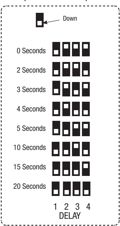
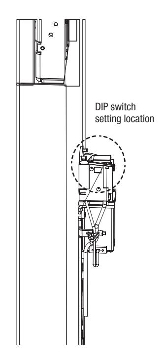
Fig. 19- Settings Location
5) LED Signaling Chart
| SIGNAL | CAUSE | TROUBLESHOOTING |
|---|---|---|
| Dark / Unlit |
Controller microprocessor
is not active |
Confirm connections and incoming
power |
| Steady Flashing (GREEN) | Normal operation | Cycle lock by closing the timer circuit |
| Solid Light (GREEN) |
Input voltage is dropping out of
operating range |
Check wire run and power supply output |
| 1 Flashes Followed by Pause (YELLOW) | Retractor sensor problem | Call 800-810-WIRE for assistance |
| 2 Flashes Followed by Pause (YELLOW) | Retractor sensor problem | Call 800-810-WIRE for assistance |
| 3 Flashes Followed by Pause (YELLOW) | Retractor sensor problem | Call 800-810-WIRE for assistance |

9 Electrical Operational Check - con't
4) TIMER MODE Troubleshooting
Prior to electrical troubleshooting, confirm that the mechanical system properly functions; i.e., that the levers fully retract all latches and rods, and the door opens freely. Refer to applicable Corbin Russwin MP9800 Series Multi-point Lock product instruction sheet to correct mechanical installation issues.

IMPORTANT: *ALWAYS disconnect power before making any mechanical adjustments to the system.
The MELR does not move when 24V/12V input is applied:
- o Check inputs to confirm proper voltage and wiring orientation. When configured for TIMER MODE, 24V/12V must be constantly applied and the timer circuit must be closed to cycle the lock.
- o Remove end cap from MELR and confirm that LED is blinking steadily when power is applied. If not, refer to LED signaling.
Note: When configured in POWER MODE, power is released to lock the lock (LED will not blink when power is released).
The onboard timer duration adjustment is not working:
- o Remove power when making adjustments to timer delay settings (DIP Switches).
- o When a momentary signal is applied to the timer circuit, the circuit must be reopened for the timer to function.
The MELR module does not fully retract or MELR module retracts completely and holds but does not open door
- o *Verify mechanical installation and correct as necessary:
- Is excessive force required to rotate lever?
- Are latches fully clearing the strikes when mechanically cycled?
The MELR module retracts and unlocks electrically but does not release. System does not relock:
- o Confirm that the TIMER MODE contact is opened (the MELR module will remain depressed until the contact is opened and the delay has expired).
- o Physically disconnect power from MELR (while electrically retracted) to verify if the issue is mechanical.
- o *Check for mechanical interference (e.g., warped door, lack of shims, misalignment of MELR, rod, etc.).
MELR behaves abnormally (multiple cycles, clicking, delayed retraction, etc.):
- o If a momentary contact is applied to the timer circuit, adjust the onboard timer to a longer duration.
- o Remove cover from MELR and confirm that LED is blinking steadily when power is applied. If not, refer to LED signaling.
For applications using automatic operator(s): Door(s) fail to unlock before doors begin to open:
- o Adjust timing of operator to allow 750ms for the MELR to fully retract.
- o If a momentary contact is applied to the timer circuit, adjust the onboard timer to a longer duration to prevent the lock from locking prior to operator actuation.

9 Electrical Operational Check - con't
For additional installation assistance, please contact 1-800-810-WIRE (9473). When calling, please provide the following information to improve our service (provide what you can):
- o Your name and contact number.
- o Corbin Russwin MP9800 Multi-Point Lock product type.
- o Location and identification of the affected opening (e.g., site, building, and door number).
- o Corbin Russwin order number (located on product box), if available.
- o Power supply manufacturer and rated output (i.e., voltage and current).
- o Method of operation (e.g.,TIMER MODE).
- o The number of locks connected to the power supply.
- o Symptoms of problem (i.e., observed behavior).

| Notes: | |||
|---|---|---|---|

Corbin Russwin 225 Episcopal Road Berlin, CT 06037 Phone: 800-810-WIRE Fax: 800-447-6714 corbinrusswin.com