Corbin Russwin MP9800 Series Multi-Point Lock Hollow Metal & Aluminum Doors Installation Instructions
Open the original PDF document
View PDFMP9800 Series Multi-Point Lock Installation Instructions
Hollow Metal & Aluminum Doors MP9800 Series Multi-Point Lock
Hollow Metal & Aluminum Doors

Hollow Metal & Aluminum Doors

Table of Contents
| 1 | Warnings | 2 |
|---|---|---|
| 2 |
General Description
3 |
|
| 3 |
MP9800 Series Multi-Point Lock Installation Instructions
4-6 |
|
| 4 |
M55 Series Installation Instructions
7-9 |
|
| 5 |
Classroom Intruder (*52) Function Series
|
10 |
Warnings 1

Changes or modifications to this unit could void the user's authority to operate the equipment.

Important: Any retrofit or other field modification to a fire rated opening can potentially impact the fire rating of the opening, and Corbin Russwin Inc. makes no representations or warranties concerning what such impact may be in any specific situation. When retrofitting any portion of an existing fire rated opening, or specifying and installing a new fire-rated opening, please consult with a code specialist or local code official (authority having jurisdiction) to ensure compliance with all applicable codes and ratings

2 General Description
The MP9800 Series Multi-Point Lock is ideal for security applications and joins the Corbin Russwin line of multi-point door security solutions. Eliminating the need for automatic flushbolts and coordinators, the MP9800 Series provides flexibility, simplicity, strength, durability, aesthetics and innovation and is perfect for a wide variety of applications including conference rooms, commercial office buildings,convention centers, upscale condominiums and residential applications, medical and educational institutions where exit devices are not required.
MP9800 Series Vertical Rod locks are available for aluminum, wood and metal doors. Single point top latching can also be specified, eliminating the bottom strike and the additional installation work required with a bottom bolt. The single point lock is specified with the M55- option. Rods are retracted by dual mounted controls with a variety of functions available.
The MP9800 Series is available for fire rated openings for wood or metal doors. Thermal pin requirements for fire rated doors:
- Double doors with two point latching on each do not require thermal pins
- Double doors with single point latching (M55-) on each require a total of 2 thermal pins, one thermal pin (supplied) for each lock
See the Corbin Russwin MP9800 Series Catalog for more information , call 1-800-438-1951, or visit www.corbinrusswin.com
Tools Required - (Same for all Series Products)
- Phillips screw driver
- Slotted screw driver
- Drill with bits
- #8-32 tap & drill
Hollow Metal & Aluminum Doors

MP9800 Series Installation Instructions

Note: For Auxiliary Controls:
Prep door BEFORE installing lock. Install Aux Control AFTER installing lock. For Aux Controls: Template: T31240 Installation Instructions: FM439
Door Preparation
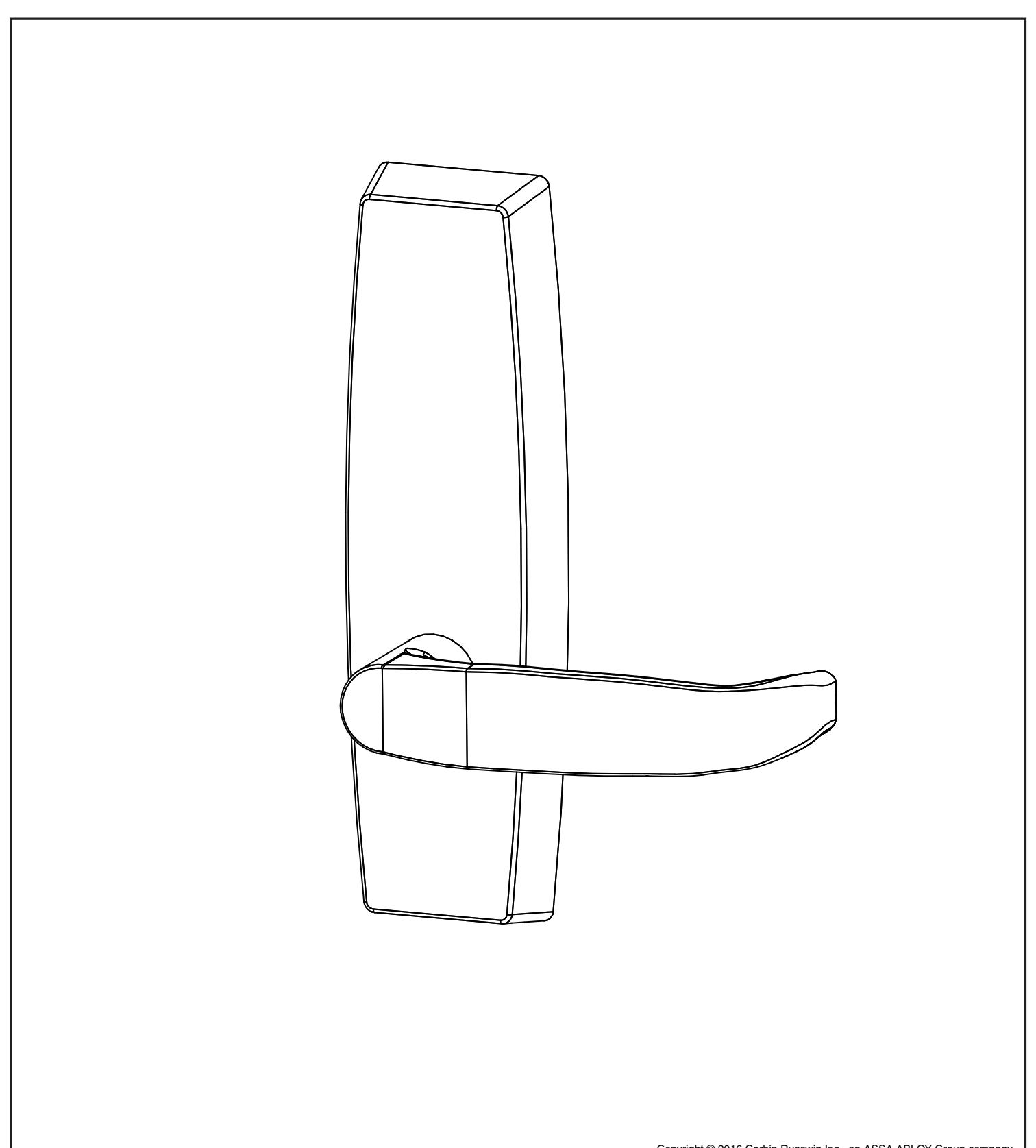
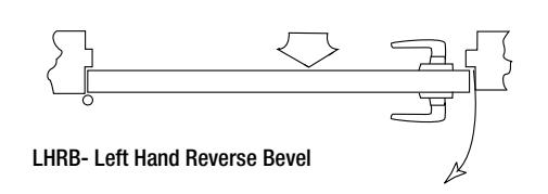
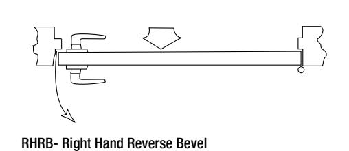
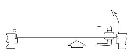
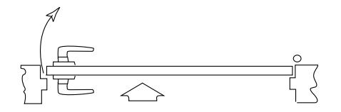
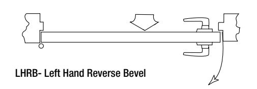
Verify Hand and Bevel of Door - (Figure 1)
- · Check hand of door. The Multi-Point lock may be handed.
- Door should be fitted and hung.
- Verify box label for size of the Multi-Point lock, function and hand.
- · Change handing if necessary.
2. Door Preparation
If door is not pre-drilled, prepare door according to template T31242. Refer to templates at www.corbinrusswin.com .
3. Hardware Supplied:


Bottom case mounting screw (1/4"-20 x 1/2" Phillips flat head machine screw 2 pcs) [not used with nb prefix]

(2) Inner chassis screws & (2) top strike screws (# 10-24 x 1/2" Phillips flat head machine screws, 4 pcs)


Top case mounting screw (#10-24 x 3/8" Phillips oval head machine screw 2 pcs)
Mounting Screw (1/4"-20 x 3" Phillips oval head mach. screw 2 pcs)
Bottom strike mounting screw (2) 1/4-20 x 2 Phillips head machine screws and (2) anchor nuts

Figure 1: Handing
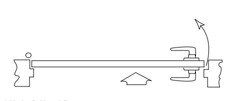
LH- Left Hand Door
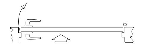
RH- Right Hand Door
Hollow Metal & Aluminum Doors

MP9800 Series Installation Instructions - Continued
Hollow Metal & Aluminum Doors

3 MP9800 Series Installation Instructions - Continued
Installation- Continued
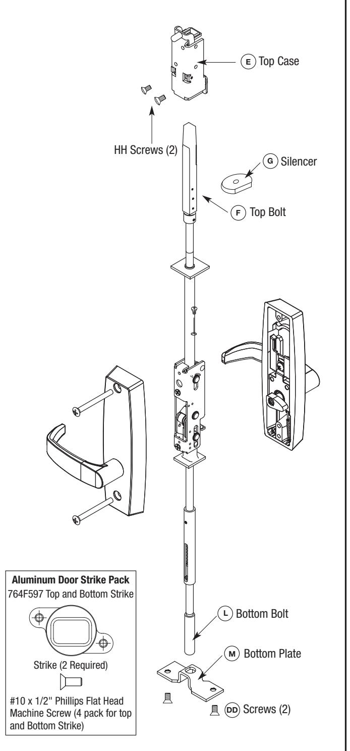
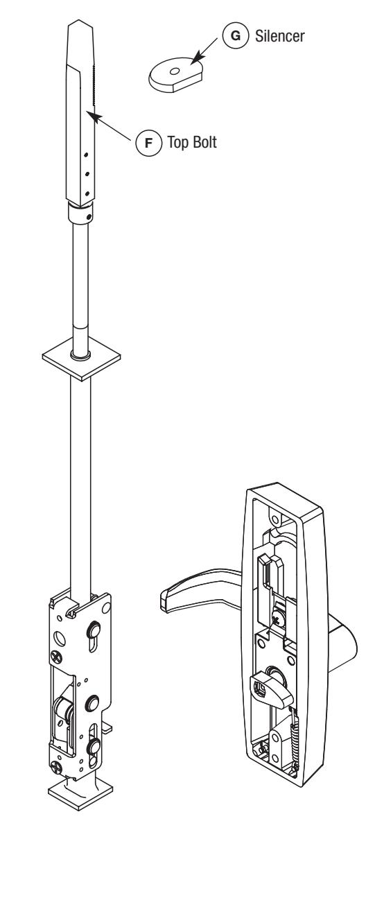
- 8. Slide rod silencer (G) over top bolt (F) onto rod. NOTE: The teeth on the rod should face the teeth on the top case.
- 9. SLIDE TOP case (E) over top bolt (F). Secure with (2) screws (HH).
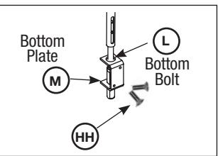
10A. Bottom Bolt for Aluminum Door:
Install bottom plate (M) over the bottom bolt (L) and secure with two #10-24 x 3/8" oval head screws (DD) using holes (6A)
#10-24 x 3/8" Oval Head Screws
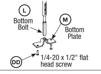
10B. Standard MP9800(B) Bottom Bolt:
Install bottom plate (M) over the bottom bolt (L) and secure with two 1/4-20 x 1/2" flat head screws (DD) using tapped holes (7A)
- 11. Install door into the frame using hinges.
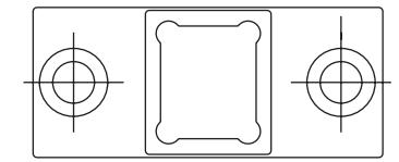
- 12. 764F577 Top Strike
ATTACH Top Strike to door frame, (2) #10-24 x 1/2" flat head screws (Reference template T31241).
13. 764F587 Bottom Strike
Attach Bottom Strike to floor under bottom bolt, (2) 1/4 - 20 x 2 Phillips head machine screws and (2) anchor nuts (Reference template T31241).
14. BEFORE CLOSING DOOR
Adjust bolts per steps 6 & 7 as needed:
- a) Either lever retracts both bolts.
- b) Bolts stay retracted (hold back).
- c) Bolts release when door closes; button inside top of door hits frame.
- d) Bolts engage strikes, 1/4"- 5/16".
Hollow Metal & Aluminum Doors


M55 Series Installation Instructions (Less Bottom Rod)

Note: For Auxiliary Controls:
Prep door BEFORE installing lock. Install Aux Control AFTER installing lock. For Aux Controls: Template: T31240 Installation Instructions: FM439
Door Preparation
Verify Hand and Bevel of Door - (Figure 1)
- · Check hand of door. The Multi-Point lock may be handed.
- Door should be fitted and hung.
- Verify box label for size of the Multi-Point lock, function and hand.
- · Change handing if necessary.
2. Door Preparation
If door is not pre-drilled, prepare door according to template T31242. Refer to templates at www.corbinrusswin.com.
3. Hardware Supplied:

(2) Inner chassis screws & (2) top strike screws (# 10-24 x 1/2" Phillips flat head machine screws, 4 pcs)


Top case mounting screw (#10-24 x 3/8" Phillips oval head machine screw 2 pcs)
Mounting Screw (1/4"-20 x 3" Phillips oval head mach. screw 2 pcs)
Figure 1: Handing
LH- Left Hand Door
RH- Right Hand Door

Hollow Metal & Aluminum Doors

4 M55 Series Installation Instructions (Less Bottom Rod) - Continued
Installation- Continued
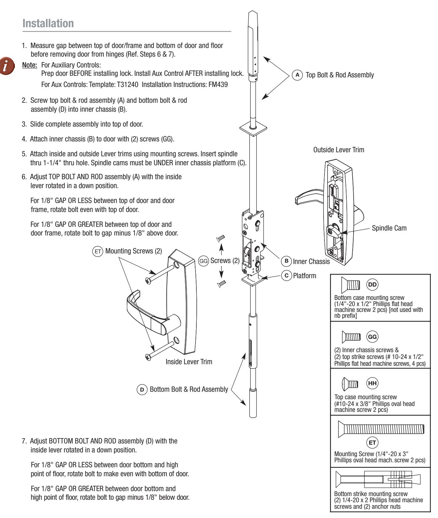
1. Measure gap between top of door/frame and bottom of door and floor before removing door from hinges (Ref. Steps 6 & 7).

Note: For Auxiliary Controls:
Prep door BEFORE installing lock. Install Aux Control AFTER installing lock. For Aux Controls: Template: T31240 Installation Instructions: FM439
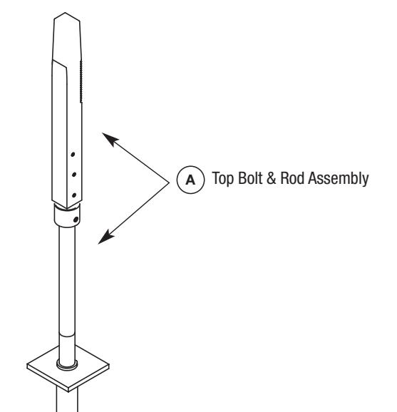
- 2. Screw top bolt & rod assembly (A) into inner chassis (B).
- 3. Slide complete assembly into top of door.
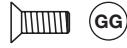
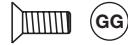
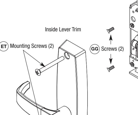
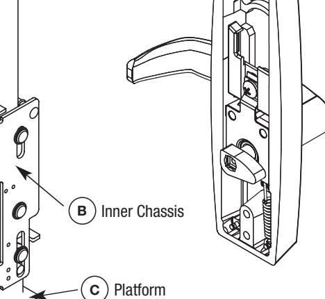
- 4. Attach inner chassis (B) to door with (2) screws (GG).
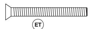
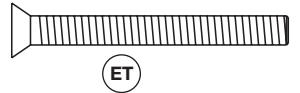
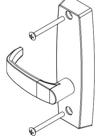
- 5. Through bolt inside and outside Lever trims using (ET) mounting screws. Spindle cams must be UNDER inner chassis platform (C).
- 6. USE INSIDE TRIM to adjust TOP BOLT AND ROD assembly (A).
For 1/8" GAP OR LESS between top of door and door frame, rotate bolt even with top of door.
For 1/8" GAP OR GREATER between top of door and door frame, rotate bolt to gap minus 1/8" above door.


Chassis mounting screw metal door application (#10-24 x 3/4" Phillips flat head mach. screws, 4 pcs)

Mounting Screw (1/4"-20 x 3" Phillips oval head mach. screws 2 pcs)

Top case mounting screw (#10-24 x 3/8" Phillips oval head machine screw 2 pcs)
Outside Lever Trim

4 M55 Series Installation Instructions (Less Bottom Rod) - Continued
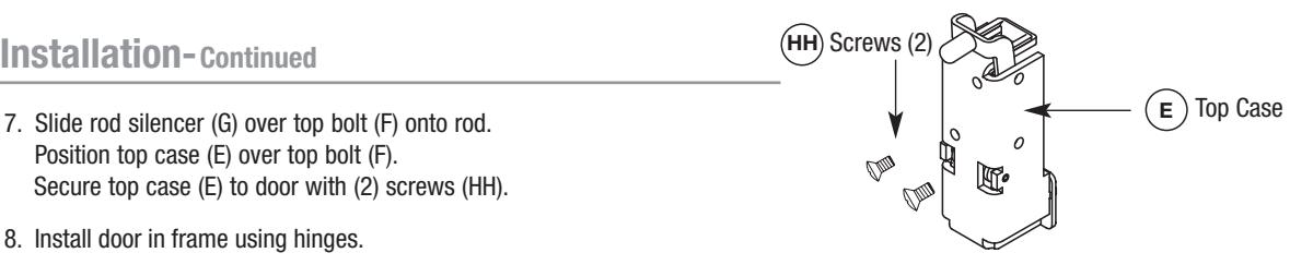
- 7. Slide rod silencer (G) over top bolt (F) onto rod. Position top case (E) over top bolt (F). Secure top case (E) to door with (2) screws (HH).
- 8. Install door in frame using hinges.
- 9. 764F577 Top Strike ATTACH Top Strike to door frame, (2) #10-24 x 1/2" flat head screws (Reference template T31241).

-
10. BEFORE CLOSING DOOR Adjust bolts per steps 6 as needed:
- a) Either lever retracts bolt.
- b) Bolt stays retracted (hold back).
- c) Bolt releases when door closes; button inside top of door hits frame.
- d) Bolt engages strike, 1/4"- 5/16".

5
CLASSROOM FUNCTION Installation Instructions
Installation
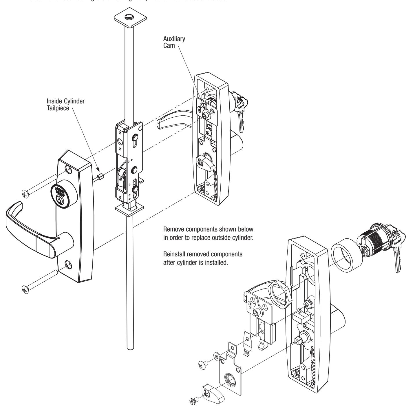
- 1. Through bolt the trim as described in Step 5 on pages 1 & 2. Ensure that the inside cylinder tailpiece engages the auxiliary cam on the outside trim.
- 2. Check for smooth locking and unlocking via cylinder on both sides of the door.

| Notes: | ||||
|---|---|---|---|---|

Corbin Russwin 225 Episcopal Road Berlin, CT 06037 Phone: 800-810-WIRE Fax: 800-447-6714 corbinrusswin.com