Corbin Russwin IN120 and IN220 Series with CLX3300 Series CLX33100 Cylindrical Locks Installation Instructions_FM638
Open the original PDF document
View PDFInstallation Instructions Cylindrical Lock


Series IN120 Wi-Fi IN220 PoE CLX33100
Attention Installer:
Please read these instructions carefully to prevent missing important steps. Improper installations may result in damage to the lock and void the factory warranty. The accuracy of the door preparation is critical for proper functioning and security of this lock. Misalignment can cause premature wear and a lessening of security.
For specific security information, please contact your local ASSA ABLOY Door Security Solutions sales consultant or call 800-810-WIRE.
For Technical Assistance call Corbin Russwin at 1-800-810-9473


| Table of Contents | |
|---|---|
| 1 |
Warning
3 |
| 2 | Regulatory & Power Specifications4 |
| 3 |
Parts Breakdown
5 |
| 4 | IN220 Wiring & Installation7 |
| 5 | Lock Installation11 |
| 6 | Operational Check21 |

1 Warning
Changes or modifications to this device not expressly approved by ASSA ABLOY could void the user's authority to operate the equipment.
FCC:
This equipment has been tested and found to comply with the limits for a Class B digital device, pursuant to Part 15 of the FCC Rules. These limits are designed to provide reasonable protection against harmful interference in a residential installation. This equipment generates, uses, and can radiate radio frequency energy and, if not installed and used in accordance with the instructions, may cause harmful interference to radio communications. However, there is no guarantee that interference will not occur in a particular installation. If this equipment does cause harmful interference to radio or television reception, which can be determined by turning the equipment off and on, the user is encouraged to try to correct the interference by one or more of the following measures:
- Reorient or relocate the receiving antenna.
- Increase the separation between the equipment and receiver.
- Connect the equipment into an outlet on a circuit different from that to which the receiver is connected.
- Consult the dealer or an experienced radio/TV technician for help.
Innovation, Science and Economic Development Canada:
Under Innovation, Science and Economic Development Canada regulations, this radio transmitter may only operate using an antenna of a type and maximum (or lesser) gain approved for the transmitter by Industry Canada. To reduce potential radio interference to other users, the antenna type and its gain should be so chosen that the equivalent isotropically radiated power (e.i.r.p.) is not more than that necessary for successful communication. Conformément à la réglementation d'Innovation, Sciences et Développement économique Canada, le présent émetteur radio peut fonctionner avec une antenne d'un type et d'un gain maximal (ou inférieur) approuvé pour l'émetteur par Industrie Canada. Dans le but de réduire les risques de brouillage radioélectrique à l'intention des autres utilisateurs, il faut choisir le type d'antenne et son gain de sorte que la puissance isotrope rayonnée équivalente (p.i.r.e.) ne dépasse pas l'intensité nécessaire à l'établissement d'une communication satisfaisante.
General Regulatory Compliance:
This device contains license-exempt transmitter(s)/receiver(s) that comply with Innovation, Science and Economic Development Canada's license-exempt RSS(s). Operation is subject to the following two conditions: (1) this device may not cause interference, and (2) this device must accept any interference received, including interference that may cause undesired operation of the device.
Ce dispositif contient des émetteurs/réceptuers exemptés de licence conformes aux RSS d'Innovation, Sciences et Développment économique Canada. L'opération est sujette aux deux conditions suivantes: (1) ce dispositif peut ne pas causer l'interférence, et (2) ce dispositif doit accepter n'importe quelle interférence reçue, y compris l'interférence qui peut causer l'opération peu désirée a le dispositif.
This equipment complies with FCC and IC radiation exposure limits set forth for general population (uncontrolled environment). This device must not be co-located or operating in conjunction with any other antenna or transmitter.
Cet équipement est conforme aux limites d'exposition aux radiations de la FCC et IC définies pour la population générale (environnement non contrôlé). Cet appareil ne doit pas être co-localisé ou fonctionner en conjonction avec une autre antenne ou un autre émetteur.

CAUTION: When using hard power, DO NOT install batteries.
AVERTIR: Ne pas installer de batteries si vous utilisez l'alimentation électrique.
CAUTION: Risk of Explosion if battery is replaced by an incorrect type. Dispose of used batteries according to the instructions. AVERTIR: Risque d'explosion si la batterie est remplacée par un type incorrect. Jetez le batteries usagées conformément aux instructions.

This product can expose you to lead which is known to the state of California to cause cancer and birth defects or other reproductive harm. For more information go to: www.P65warnings.ca.gov.
Ce produit peut vous exposer au plomb qui, dans l'état de la Californie, est reconnu pour causer le cancer, des anomalies congénitales ou d'autres problèmes de reproduction.
Pour plus d'informations, visitez: www.P65warnings.ca.gov.

Any retrofit or other field modification to a fire rated opening can potentially impact the fire rating of the opening, and Corbin Russwin makes no representations or warranties concerning what such impact may be in any specific situation. When retrofitting any portion of an existing fire rated opening, or specifying and installing a new fire-rated opening, please consult with a code specialist or local code official (Authority Having Jurisdiction) to ensure compliance with all applicable codes and ratings.

To avoid possible damage from electrostatic discharge (ESD), some basic precautions should be used when handling electronic components:
- Minimize build-up of static by touching and/or maintaining contact with unpainted metal surfaces such as door hinges, latches, and mounting plates especially when mounting electronic components such as readers and controllers onto the door.
- Leave components (reader and controller) protected in their respective anti-static bags until ready for installation
- Do not touch pins, leads or solder connections on the circuit boards

2 Regulatory and Power Specifications
Electronic Authentication Specifications (Mobile Credentials)
For Mobile Credential-Enabled versions of this electronic lock (Indicated by the credential code in the product order string):
- Mobile Credentials are transmitted to the lock via Bluetooth Smart or NFC ISO/IEC14443 and must use a mobile device enabled with these technologies.
- Credential and mobile device versions are specified by the credential provider.
- User must acquire the latest HID "Mobile Access" application available from Apple iStore or Android PlayStore.
This product is not intended for outside wiring as covered by Article 800 in the National Electrical Code, NFPA 70.
Compliance with IEEE 802.3 (at or af) specifications was not verified as part of UL 294/B.
The system shall not be installed in the fail-secure mode unless permitted by the local authority having jurisdiction and shall not interfere with the operation of Listed panic hardware.
- UL Listed UL 294 Indoor Use
- CUL Listed ULC-60839-11-1, Grade 1
• UL 294 Access Control Ratings:
| Destructive Attack | Level 1 |
|---|---|
| Line Security | Level 1 |
| Endurance | Level 4 |
| Standby Power | Level 1 |
Power Supply Specifications
IN220 (PoE version):
-
Power over Ethernet:
- Use UL 294 Listed, PoE Injector or Class 2 power limited power supply (55VDC, 90mA)
- UL testing was conducted on product powered by UL listed model POE20U-560(G) PoE Injector, manufactured by Phihong
IN120 (Wi-Fi version):
• Battery Power:
Alkaline AA Batteries (6): 9V, 300mA

(To comply with "Fire Listed" doors, batteries must be replaced with alkaline batteries only)
• Optional Hard Power (UL 294 Listed Power Supply Required): 9-24VDC, 300mA
CAUTION: When using Hard Power, DO NOT install batteries.
CAUTION: Risk of explosion if battery is replaced by an incorrect type. Dispose of used batteries according to the instructions.
Wiring methods shall be in accordance with the National Electrical Code (ANSI/NFPA70), CSA 22.1, Canadian Electrical Code (CEC), Part I, Safety Standard for Electrical Installations, local codes and the authorities having jurisdiction.

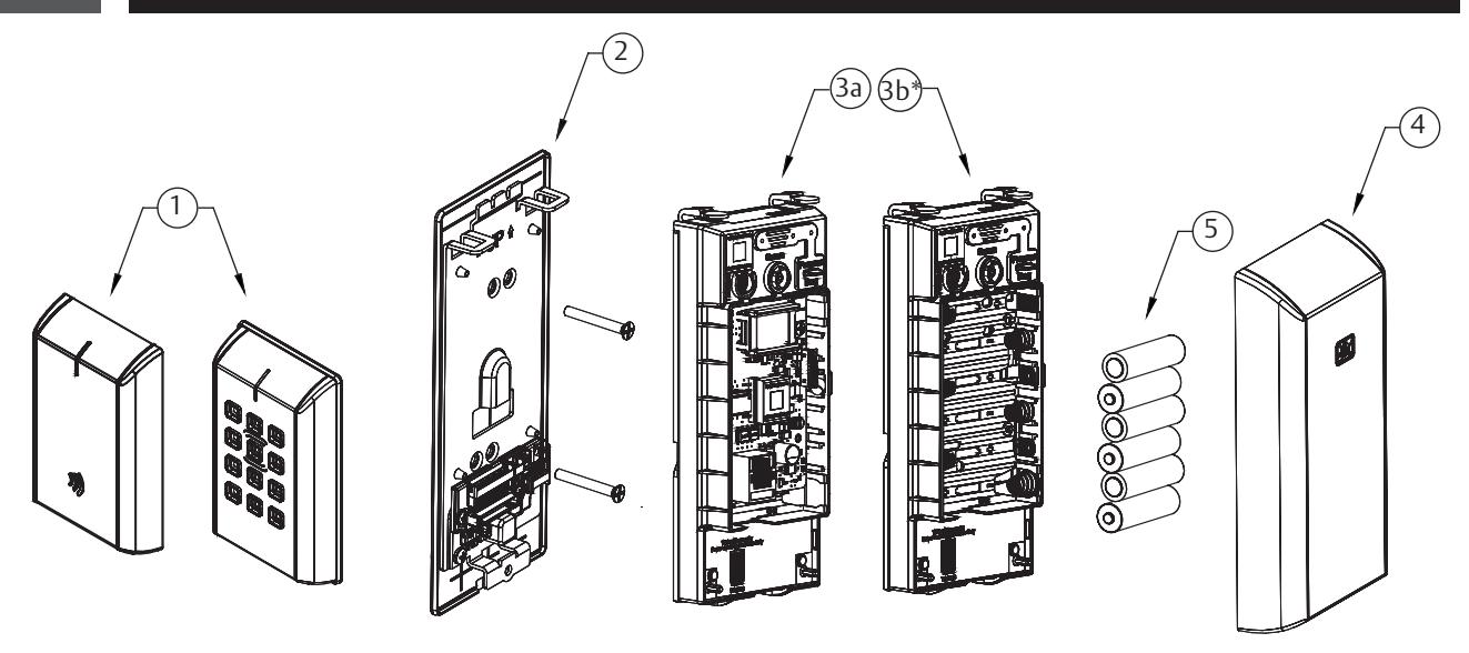
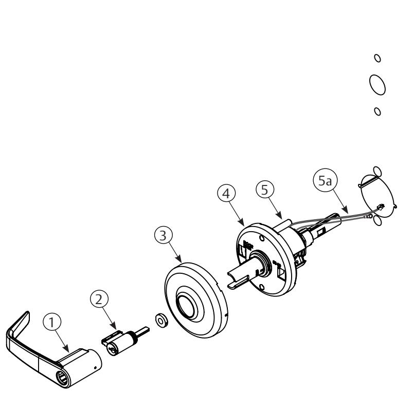
3 Parts Breakdown
| ITEM No. | DESCRIPTION |
|---|---|
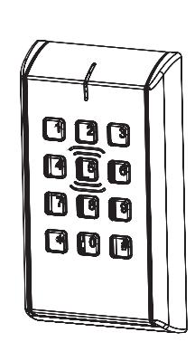
| 1* | Outside Escutcheon Assembly |
| 2 | Inside Mounting Plate Assembly (includes Gasket) |
| 3a | PoE Controller Assembly |
| 3b | Wi-Fi Controller Assembly* (batteries included) |
| 4 | Inside Escutcheon Assembly with Privacy Button |
| 5 | AA alkaline batteries (6) |
* Consult catalog for electronic replacement part numbers

3 Parts Breakdown continued
Tools Required:
- Phillips Screw Driver #2, #3
- Flat Blade Screw Driver (Standard size)
- 1/8" Security Hex Wrench
| ITEM | DESCRIPTION | REQ'D |
|---|---|---|
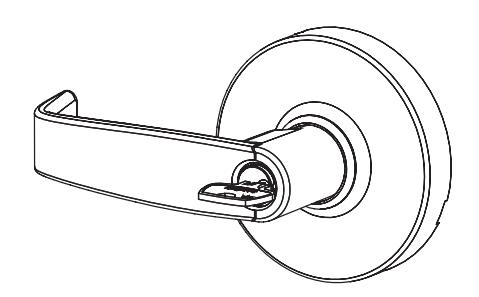
| 1 | Outside Lever (Reference Catalog for Available Styles) | |
| 2 |
Cylinder Assembly (Reference Catalog for Available Cylinders)
1 |
|
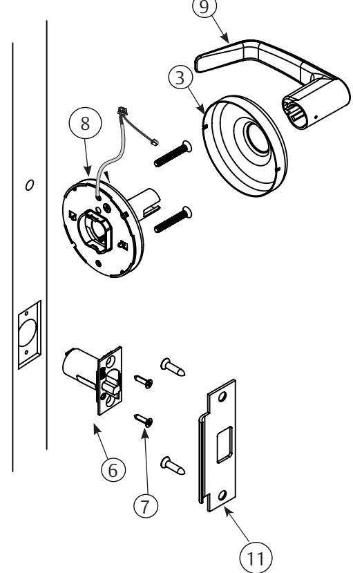
| 3 |
Rose (Reference Catalog for Avalable Styles)
2 |
|
| 4 | Outside Rose Spring Assembly | 1 |
| 5 | Lockbody Assembly CLX33134 | 1 |
| 5a | Lockbody Harness | 1 |
| 6 | Latch Assembly | 1 |
| 7 | Screw Pack | 2 |
| 8 | Inside Rose Spring Assembly | 1 |
| 9 | Inside Lever (Reference Catalog for Available Styles) | 1 |
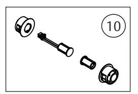
| 10 | Door Position Switch Kit | 1 |
| 11 | Strike | 1 |
For parts not listed, refer to CLX3300 Parts and Service Manual

Important Note: If you are installing IN220 (PoE)
Before installing IN220 (PoE) cylindrical device, please read the following section: - IN220 (PoE) Wiring & Installation
4 IN220 (PoE) Wiring & Installation
Corbin Russwin IN220 PoE Typical Application
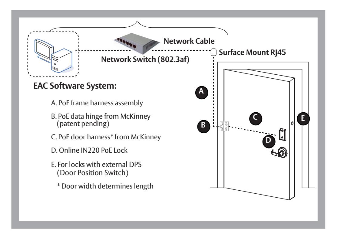
Wiring methods shall be in accordance with the National Electrical Code (ANSI/NFPA70), CSA 22.1, Canadian Electrical Code (CEC), Part I, Safety Standard for Electrical Installations, local codes, and the authorities having jurisdiction.

4 IN220 (PoE) Wiring & Installation (Continued)
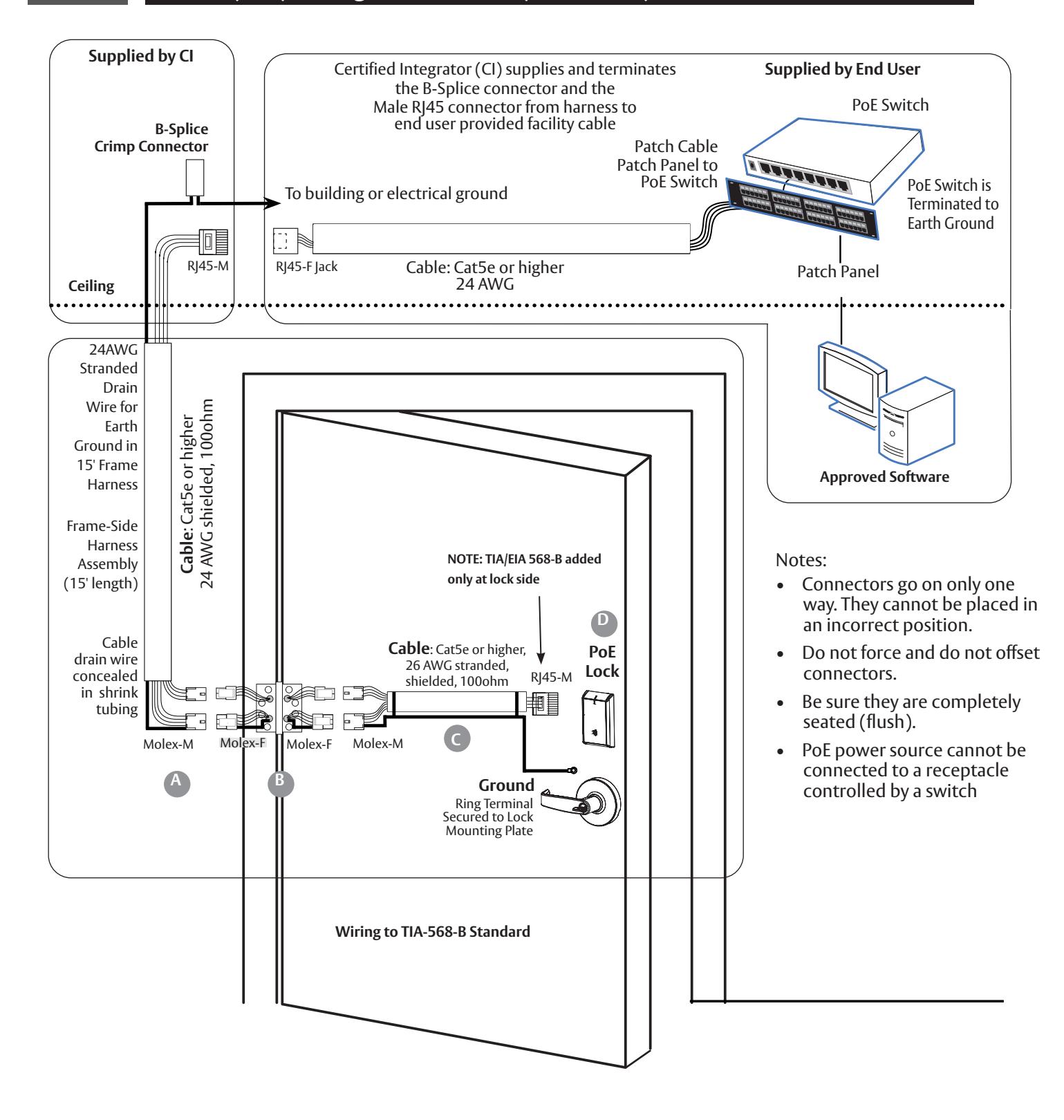

4 IN220 (PoE) Wiring & Installation (Continued)

Frame Harness Installation
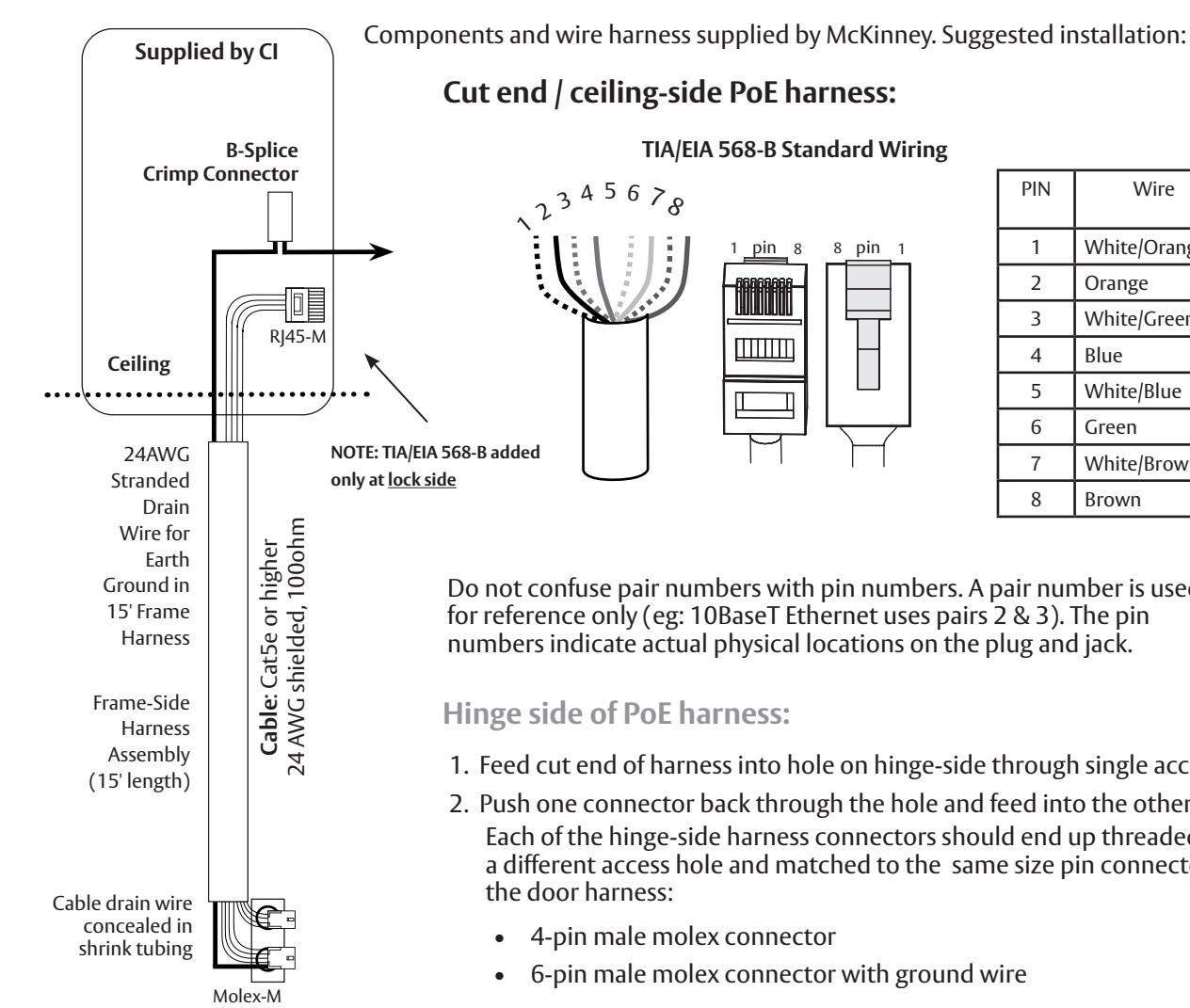
| PIN | Wire |
Pair
Number |
| 1 | White/Orange | 2 |
| 2 | Orange | 2 |
| 3 | White/Green | 3 |
| 4 | Blue | 1 |
| 5 | White/Blue | 1 |
| 6 | Green | 3 |
| 7 | White/Brown | 4 |
| 8 | Brown | 4 |
Do not confuse pair numbers with pin numbers. A pair number is used for reference only (eg: 10BaseT Ethernet uses pairs 2 & 3). The pin numbers indicate actual physical locations on the plug and jack.
Hinge side of PoE harness:
- 1. Feed cut end of harness into hole on hinge-side through single access hole.
-
2. Push one connector back through the hole and feed into the other access hole. Each of the hinge-side harness connectors should end up threaded through a different access hole and matched to the same size pin connector from the door harness:
- 4-pin male molex connector
- 6-pin male molex connector with ground wire
Frame-Side Harness Assembly (15' length)
Cable drain wire concealed in shrink tubing
Earth Ground in 15' Frame Harness
PoE Data Hinge
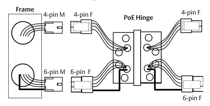
Hinge-side harness connectors:
- 4-pin female molex connector
- 6-pin female molex connector with ground wire
Lock-side harness connectors:
- 4-pin female molex connector
- 6-pin female molex connector with ground wire

4 IN220 (PoE) Wiring & Installation (Continued)
C PoE Door Harness
Order of installation may vary. Refer to appropriate sections for instructions. Hinge-side harness connectors:
- 4-pin male Molex connector
- 6-pin male Molex connector with ground wire
Lock-side harness connectors:
- Ring terminal
- Male RJ45 connector (crimped after cable is fed through door)
Notes:
- Connectors go on only one way. They cannot be plugged to incorrect position.
- Do not force and do not offset connectors.
- Be sure they are completely seated (flush).
IN220 PoE Lock
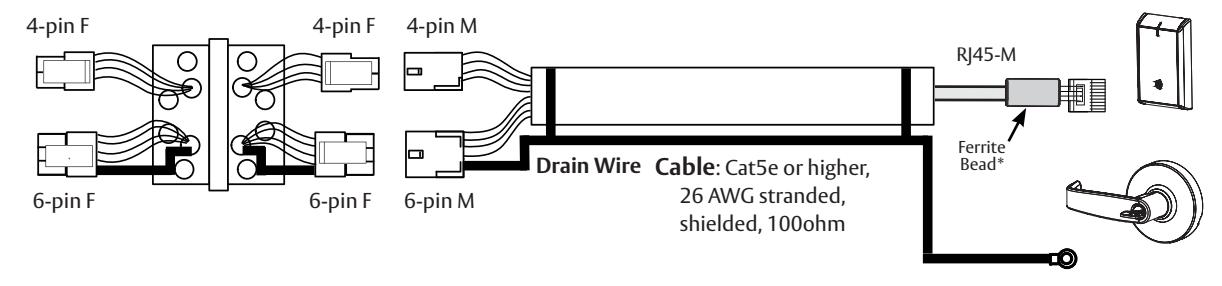
D PoE Lock
Order of installation may vary. Refer to appropriate sections for instructions.
- 1. Prop door open.
- 2. Using the ring terminal, carefully route the assembly through the door channel to the lock.
*Do not terminate PoE harness (with RJ45 M) until cable has been routed through door and inside mounting plate assembly. See Section 5, Step 11 - Installing the Connectors.

5 Lock Installation
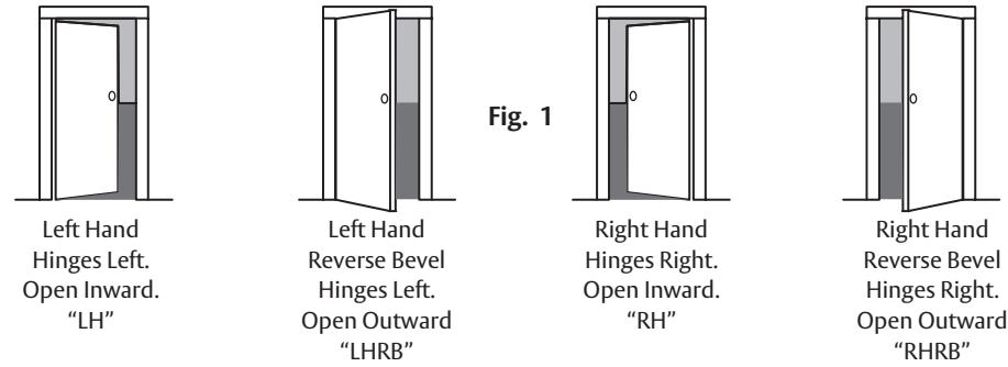
1 Verify Hand and Bevel of Door
Illustrations shown are as viewed from the outside or secure side of opening.
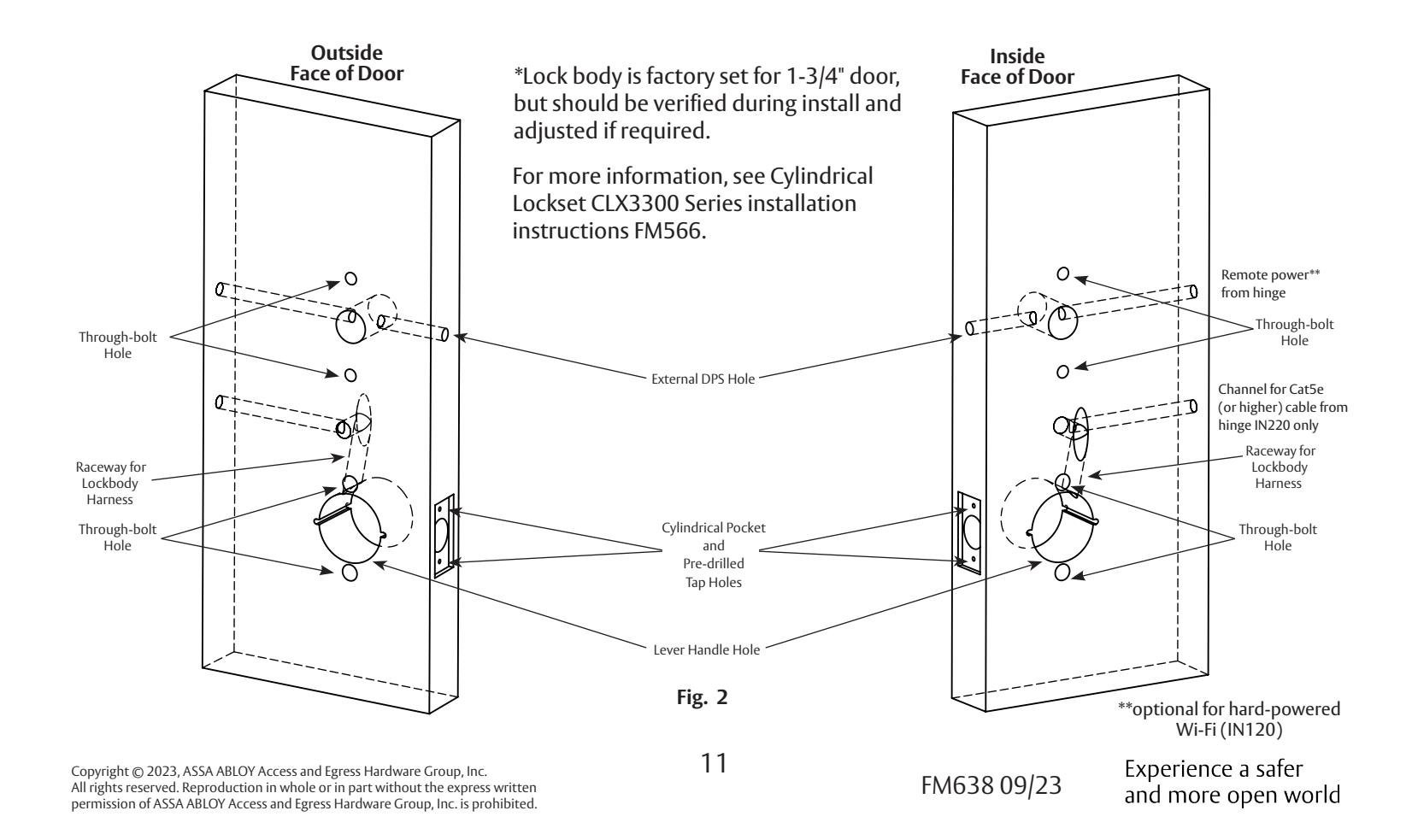
2 Door Preparation (Wood Door shown)
Prep door according to supplied door marker FM649*. For door manufacturer templates visit www.corbinrusswin.com and reference template # T31203.
Note: Be sure to verify backset before marking & drilling door.

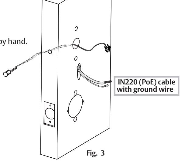
3 Install Door Position Switch (DPS)
a. Insert DPS into the raceway on the latch edge of the door.
b. Push wires through raceway toward lock prep.
c. Push DPS firmly into place by hand. Note: DO NOT TAP SWITCH WITH ANY TOOL.
d. Install magnet into door frame. Push firmly into place by hand. See instruction A7983.
CAUTION: if DPS is not installed or is installed improperly, door status monitoring features will not function.
4 Install Latch Bolt
Install latch bolt with beveled bolt facing the strike using two #8 x 3/4" combination screws (Fig. 4):
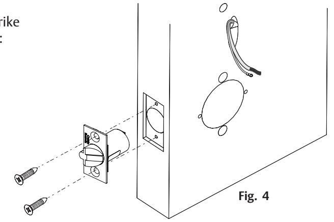
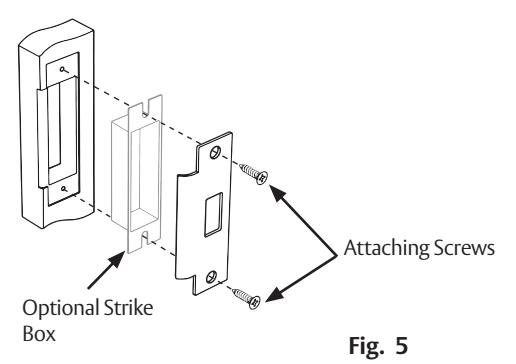
5 Install Strike Plate
Install strike plate using two #12 x 1" combination screws (Fig. 5):

6 Install Lock Body
- a. Feed lock body and wire through 2-1/8" diameter hole from outside of door (Fig. 6a). Be sure latch engages lock body as shown (Fig. 6b).
- b. Connect 4-pin connector from lock body to 4-pin on cassette
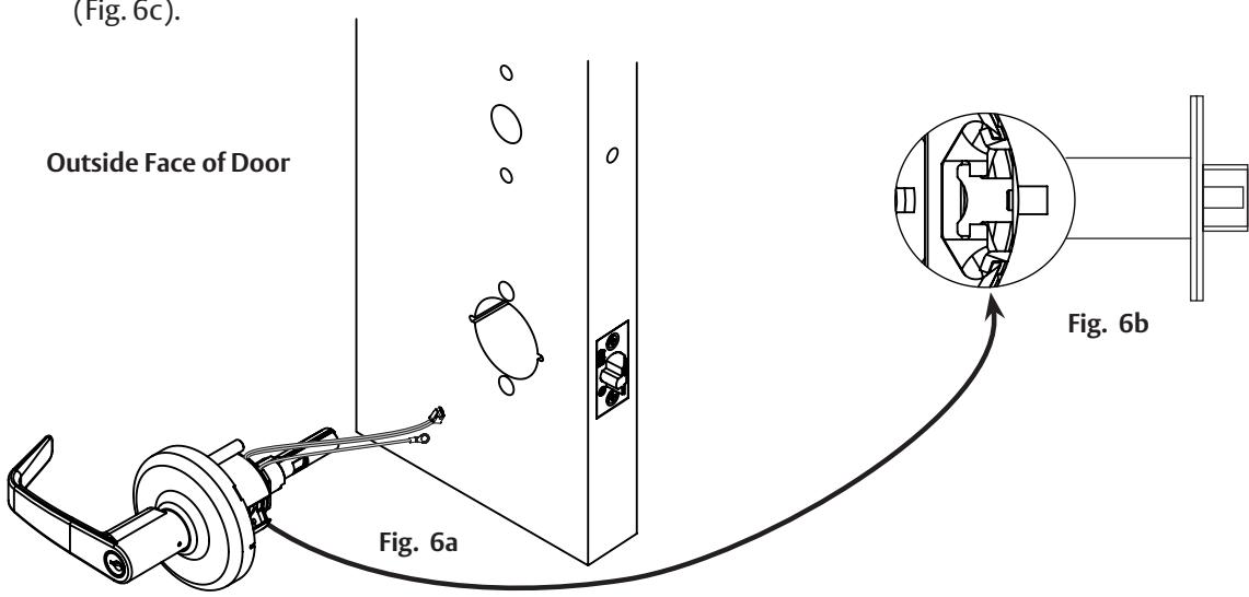
c. Temporarily install top throughbolt to hold chassis in door (Fig. 6c). Important: Door must remain open during installation. Use door stop.

7 Install Inside Spring Housing Assembly
- a. Feed harness wires and ground wire up through raceway (Fig. 7a).
- b. Remove screw from previous step.
- c. Slide on cassette and secure with (2) #12-24 x 1-1/2" through-bolts (Fig. 7b) and then install rose and lever.


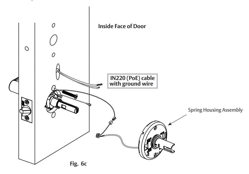
8 Install Outside Reader
- a. Orient the reader so the LED lens is at the top.
- b. Feed the reader harness through the door (from outside to inside).
- c. Install the reader to the outside of door by aligning the mounting posts with the door preparation holes. Hold the reader flush against door while ensuring proper alignment.

9 Install Inside Mounting Plate
- a. Next feed cables/connectors through inside mounting assembly (and gasket if required*).
- b. Secure the mounting assembly while ensuring proper alignment of outside reader and tighten the (2) through-bolts on the inside of the door to secure the reader (Fig. 9a).
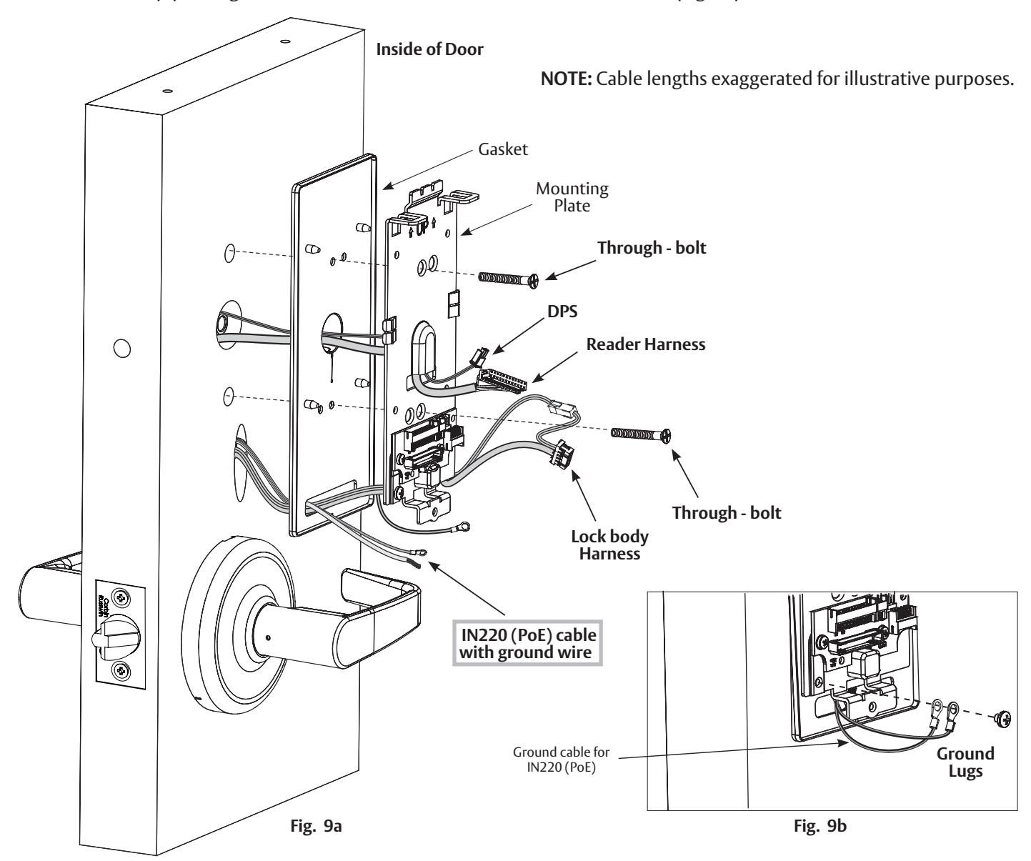
c. Secure both ground lug(s) with #6-32 machine screw (Fig. 9b).
FM638 09/23
*Gasket is required for outdoor installations. Do not use gasket for fire-rated openings.
If installing with gasket; separate gasket from mounting plate to feed cables/connectors through holes as indicated (Fig. 9a).
Once cables/connectors are fed through, reattach gasket to mounting plate.
10 Installation of Connectors
Important Note: Before you secure the connectors
CAUTION - Do not allow debris to enter connector contacts
Ensure connectors are covered with silicone dielectric compound (grease)*

- Snip end of packet to dispense grease
- Ensure all connector pins and contacts (Fig. 10a) are covered - do not overfill or over-apply**
*Supplied tube contains 5 grams of silicone dielectric compound (grease)
**Evenly distribute grease; full application requires approximately 2.5 grams
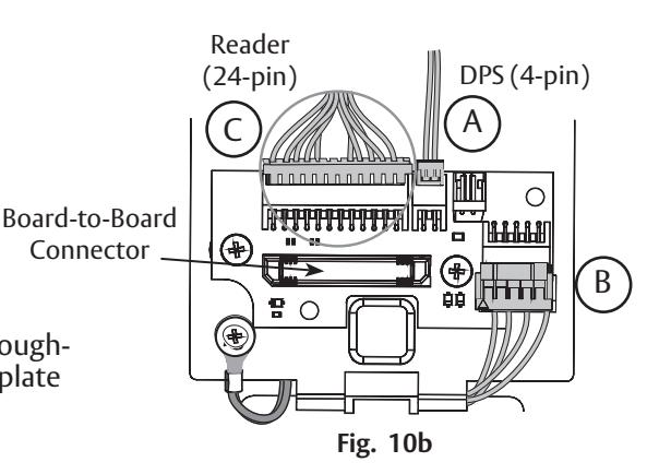
IMPORTANT: Do not run wires through bottom flange hole in plate (Fig. 10a, b) - it will damage wires and the controller connector. Route wires around flange.

A. Secure the 4-pin DPS connector.
B. Secure the 10-pin lock body assembly connector.
Secure Mounting Plate
- Tuck excess cable into wire hole on inside of door
- Secure the mounting assembly while ensuring proper alignment of outside reader and fully tighten the (2) throughbolts on the inside of the door to secure the reader and plate to the door
- C. Secure the 24-pin card reader connector (Fig. 10b, c). Fig. 10b
- D. Ensure all openings on back of secured reader connector are covered completely with grease (Fig. 10c).
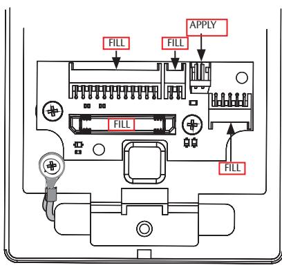
Fig. 10a
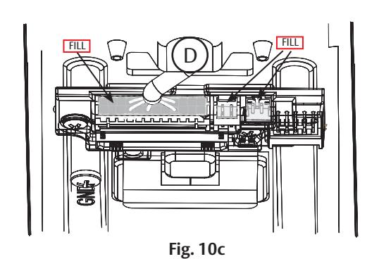

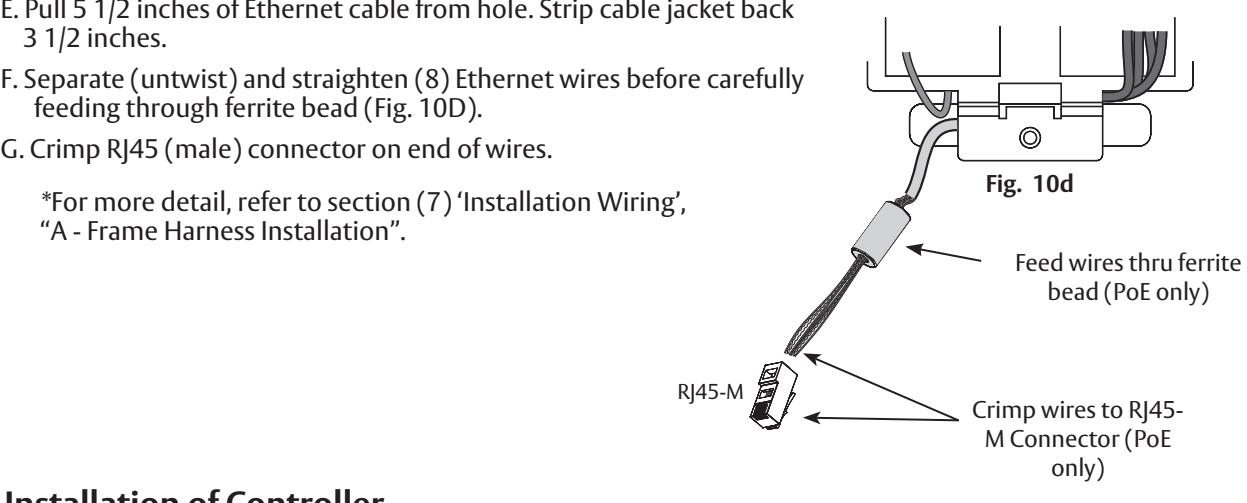
10 Installation of Connectors (Continued)
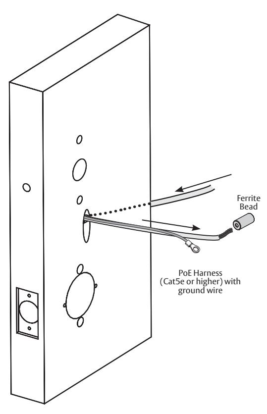
Important Note: If you are installing IN220 (PoE)*:
3 1/2 inches. F. Separate (untwist) and straighten (8) Ethernet wires before carefully feeding through ferrite bead (Fig. 10D).
G. Crimp RJ45 (male) connector on end of wires.
*For more detail, refer to section (7) 'Installation Wiring',
"A - Frame Harness Installation".
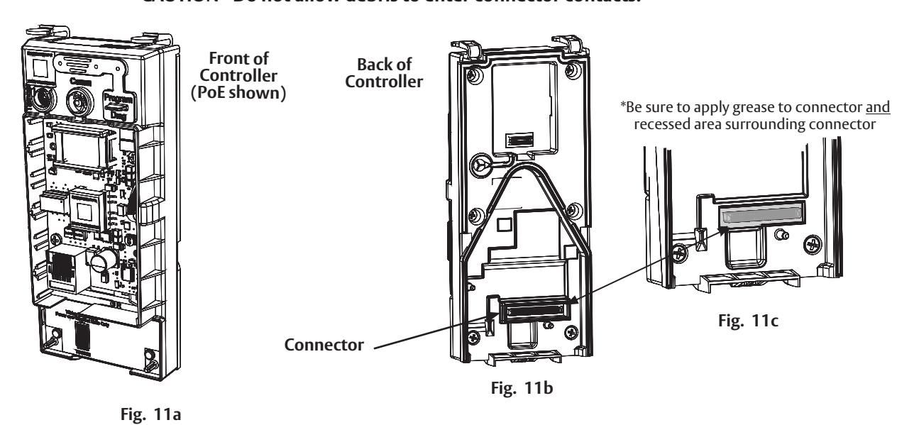
11 Installation of Controller
Important Note: Before you install the IN220 (PoE) controller
CAUTION - Do not allow debris to enter connector contacts. Apply dielectric grease to connector* located on back of Controller (Fig. 11b, c).

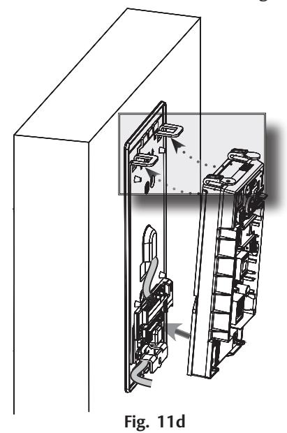
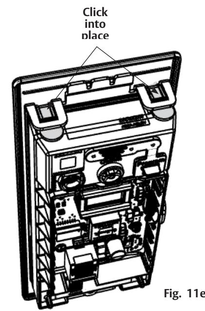
11 Installation of Controller (Continued)
- a. Insert bottom tab of controller (ensure a clear path) into slot on mounting plate (Fig. 11d, e).
- b. Ensure proper alignment of board-to-board connectors (Fig. 11e) while pivoting controller toward door until two tabs on top click securely into place on mounting plate (Fig. 11d).
CAUTION : To avoid possible damage to board-to-board connectors, care should be taken when securing controller to mounting plate. If there is resistance when securing, detach controller to determine cause before re-attaching controller.
12 Supplying Power to the Controller
Important - before inserting PoE plug into PoE connector, apply dielectric grease to top of plug, covering the pin area (Fig. 12a).
A. IN220 (PoE)
- 1. Once controller is securely in place, connect RJ45 male connector to female RJ45 port on controller board (Fig. 12a).
- 2. If power is enabled, LED will flash and lock motor will cycle.

12 Supplying Power to the Controller (Continued)
-
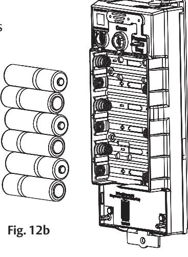
B. IN120 (Wi-Fi)
- a. Once controller is securely in place, place (6) "AA" alkaline batteries in the compartment, being careful to align polarity properly.
- b. After batteries are installed, there is a slight delay; LED will flash and the lock motor will cycle.
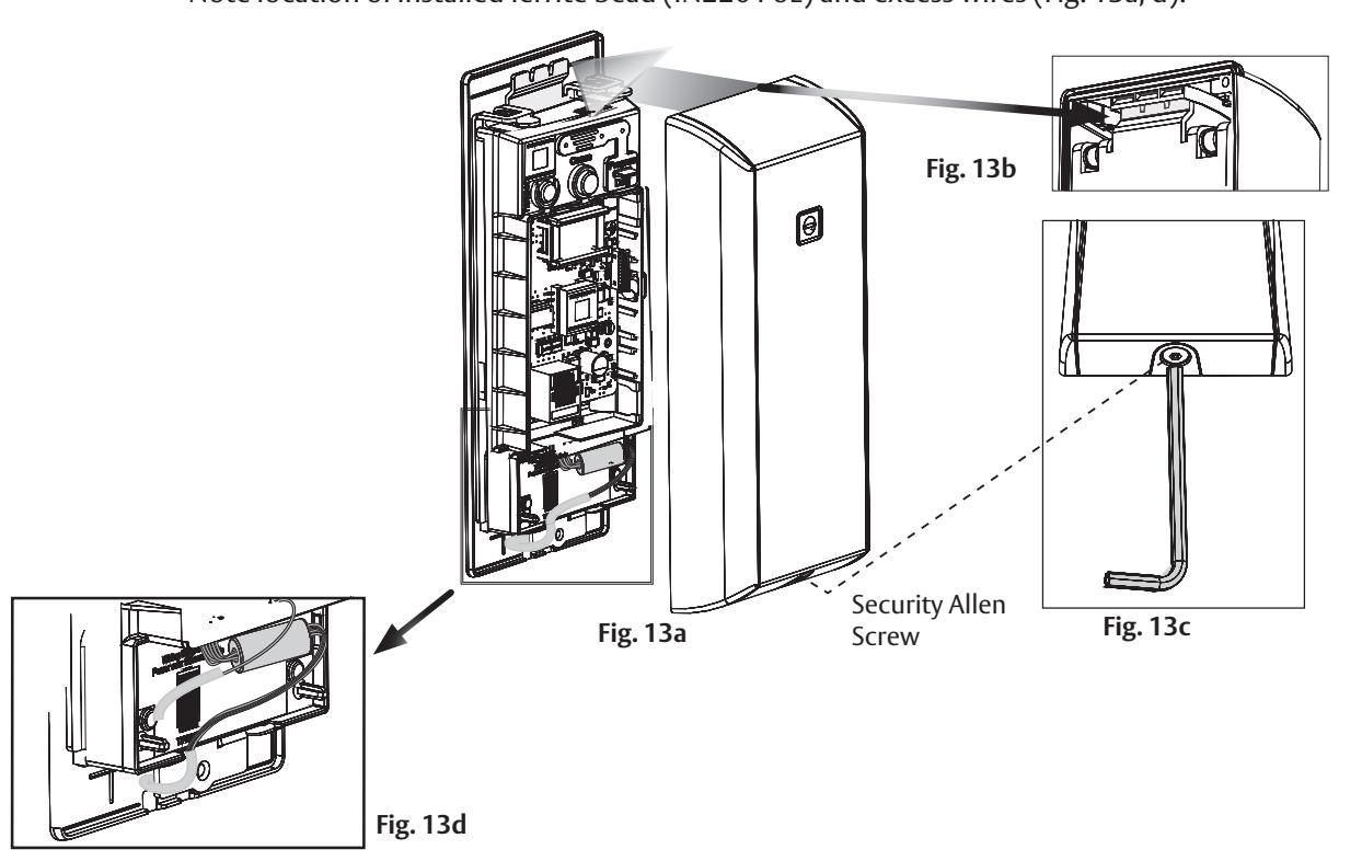
13 Inside Cover Installation
- a. Assemble cover by hooking top edge on inside mounting plate taking care not to pinch gasket (top edge goes between plate and gasket).
- b. Carefully press bottom of cover toward door without pinching any wires.
- c. Secure the cover with a security allen wrench.
FM638 09/23
*Note location of installed ferrite bead (IN220 PoE) and excess wires (Fig. 13a, d).

6 Operational Check
When lock is fully installed, perform the following steps:
IMPORTANT: Be sure to test functions prior to closing door.
a. Insert key into cylinder and rotate:
The key will retract the latch. The key should rotate freely.
b. Ensure inside lever retracts latch.
c. Close door, ensure latch is fully extended and does not bind.
In all cases, perform the following checks:
- For units without a keypad, add card using LCT software* and test.
- For units with a keypad, add pin and card using LCT software* and test.
* 20 seconds after being configure with the LCT software, the lock goes into "lock" mode (single beep with lock motor actuation), credentials are needed to unlock the door.
LCT software is available at: https://go.intelligentopenings.com/lct
LED signaling:
- After using a valid credential a green flash followed by motor unlock indicates normal operation (lock unlocks)
- After using a valid credential a green flash followed by 4 beeps and 4 fast purple flashes indicates low power. Check the input voltage.
- If the input voltage is low, disconnect lock from power source and check power source voltage. If power source voltage is correct, inspect lock wiring for a possible short.
- If the lock loses power, it will flash rapid blue for approximately one minute. Lock will default to programmed fail safe or fail secure.
- After that, the lock will no longer be functional.
When you have completed the tests, close the door, ensuring latchbolt fully extends into strike plate without binding.
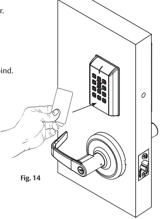
Note: The credential should be presented about 1/2 inch parallel to the contact marking, as indicated in the image above, to ensure that the credential is read properly.
Do not wave credential.


IN120 & IN220 Series CLX33100 Cylindrical Lock

FM638 09/23

Corbin Russwin 225 Episcopal Road Berlin, CT 06037 Phone: 800-543-3658 Fax: 800-447-6714 corbinrusswin.com
Copyright © 2023 ASSA ABLOY Access and Egress Hardware Group, Inc. All rights reserved. Reproduction in whole or in part without the express written permission of ASSA ABLOY Access and Egress Hardware Group, Inc. is prohibited. Patent pending and/or patent - www.assaabloydss.com/patents. HID, iCLASS, and Edge are trademarks or registered trademarks of HID Global Corporation.