Corbin Russwin IN120 and IN220 Series with BL6600, FE6600, and MP6600 Series Multi-Point Locks Installation Inst…_FM455
Open the original PDF document
View PDFInstallation Instructions

IN120 & IN220
Wi-Fi and Power over Ethernet (PoE)
with FE6600/BL6600/MP6600 Series Multi-Point Lock
For Technical Assistance call Corbin Russwin at 1-800-810-WIRE(9473)
IN120 / IN220
FE6600/BL6600/MP6600 Series Multi-point Lock

Installation Instructions
| TOC | Table of Contents |
|---|---|
| 1 |
Warning
3 |
| 2 |
General Description
4 |
| 3 |
Hardware Specifications
4 |
| 4 |
Electronic Specifications
|
| 5 |
Parts Breakdown
5 |
| 6 |
IN220 (PoE) Wiring & Installation
7 |
| 7 |
Installation Instructions
11 |
| 8 |
Operational Check
23 |
Copyright © 2019-2021 ASSA ABLOY Access and Egress Hardware Group, Inc. All rights reserved. Reproduction in whole or in part without the express written permission of ASSA ABLOY Access and Egress Hardware Group, Inc. is prohibited.
IN120 / IN220
FE6600/BL6600/MP6600 Series Multi-point Lock
Installation Instructions

1 Warning

This product can expose you to lead which is known to the state of California to cause cancer and birth defects or other reproductive harm. For more information go to www.P65warnings.ca.gov .
Ce produit peut vous exposer au plomb qui, dans l'état de la Californie, est reconnu pour causer le cancer, des anomalies congénitales ou d'autres problèmes de reproduction. Pour plus d'informations, visitez: www.P65warnings.ca.gov .
Changes or modifications to this device not expressly approved by ASSA ABLOY could void the user's authority to operate the equipment.
FCC:
This equipment has been tested and found to comply with the limits for a Class B digital device, pursuant to Part 15 of the FCC Rules. These limits are designed to provide reasonable protection against harmful interference in a residential installation. This equipment generates, uses, and can radiate radio frequency energy and, if not installed and used in accordance with the instructions, may cause harmful interference to radio communications. However, there is no guarantee that interference will not occur in a particular installation. If this equipment does cause harmful interference to radio or television reception, which can be determined by turning the equipment off and on, the user is encouraged to try to correct the interference by one or more of the following measures:
- Reorient or relocate the receiving antenna.
- Increase the separation between the equipment and receiver.
- Connect the equipment into an outlet on a circuit different from that to which the receiver is connected.
- Consult the dealer or an experienced radio/TV technician for help.
Industry Canada:
This Class B digital apparatus meets all requirements of the Canadian Interference Causing Equipment Regulations. Operation is subject to the following two conditions: (1) this device may not cause harmful interference, and (2) this device must accept any interference received, including interference that may cause undesired operation.
Cet appareillage numérique de la classe B répond à toutes les exigences de l'interférence canadienne causant des règlements d'équipement. L'opération est sujette aux deux conditions suivantes: (1) ce dispositif peut ne pas causer l'interférence nocive, et (2) ce dispositif doit accepter n'importe quelle interférence reçue, y compris l'interférence qui peut causer l'opération peu désirée.
"This equipment complies with FCC radiation exposure limits set forth for an uncontrolled environment. This equipment should be installed and operated with minimum distance 20cm between the radiator and your body. This transmitter must not be co-located or operating in conjunction with any other antenna or transmitter."
Under Industry Canada regulations, this radio transmitter may only operate using an antenna of a type and maximum (or lesser) gain approved for the transmitter by Industry Canada. To reduce potential radio interference to other users, the antenna type and its gain should be so chosen that the equivalent isotropically radiated power (e.i.r.p.) is not more than that necessary for successful communication.
Conformément à la réglementation d'Industrie Canada, le présent émetteur radio peut fonctionner avec une antenne d'un type et d'un gain maximal (ou inférieur) approuvé pour l'émetteur par Industrie Canada. Dans le but de réduire les risques de brouillage radioélectrique à l'intention des autres utilisateurs, il faut choisir le type d'antenne et son gain de sorte que la puissance isotrope rayonnée équivalente (p.i.r.e.) ne dépasse pas l'intensité nécessaire à l'établissement d'une communication satisfaisante.

Any retrofit or other field modification to a fire rated opening can potentially impact the fire rating of the opening, and SARGENT Manufacturing makes no representations or warranties concerning what such impact may be in any specific situation. When retrofitting any portion of an existing fire rated opening, or specifying and installing a new fire-rated opening, please consult with a code specialist or local code official (Authority Having Jurisdiction) to ensure compliance with all applicable codes and ratings.

To avoid possible damage from electrostatic discharge (ESD), some basic precautions should be used when handling electronic components:
- Minimize build-up of static by touching and/or maintaining contact with unpainted metal surfaces such as door hinges, latches, and mounting plates especially when mounting electronic components such as readers and controllers onto the door.
- Leave components (reader and controller) protected in their respective anti-static bags until ready for installation.
- Do not touch pins, leads or solder connections on the circuit boards.
Copyright © 2019-2021 ASSA ABLOY Access and Egress Hardware Group, Inc. All rights reserved. Reproduction in whole or in part without the express written permission of ASSA ABLOY Access and Egress Hardware Group, Inc. is prohibited.
Installation Instructions

2 Regulatory and Power Specifications
Electronic Authentication Specifications (Mobile Credentials)
For Mobile Credential-Enabled versions of this electronic lock
(Indicated by the credential code in the product order string):
- Mobile Credentials are transmitted to the lock via Bluetooth Smart or NFC ISO/IEC14443 and must use a mobile device enabled with these technologies
- Credential and mobile device versions are specified by the credential provider
- User must acquire latest HID "Mobile Access" application available from Apple iStore or Android PlayStore
This product is not intended for outside wiring as covered by Article 800 in National Electrical Code, NFPA 70.
Compliance with IEEE 802.3 (at or af) specifications was not verified as part of UL 294/B.
The system shall not be installed in the fail-secure mode unless permitted by the local authority having jurisdiction and shall not interfere with the operation of Listed panic hardware.
- UL Listed UL 294 Indoor Use
- CUL Listed ULC-60839-11-1, Grade 1
• UL 294 Access Control Ratings:
| Destructive Attack | Level 1 |
|---|---|
| Line Security | Level 1 |
| Endurance | Level 4 |
| Standby Power | Level 1 |
Power Supply Specifications
IN220 (PoE version):
- Power over Ethernet: Use UL 294 Listed, PoE Injector or Class 2 power limited power supply (55VDC, 90mA)
- UL testing was conducted on product powered by UL listed model POE20U-560(G) PoE Injector, manufactured by Phihong
IN120 (Wi-Fi version):
• Battery Power:
Alkaline AA Batteries (6): 9V, 300mA
(To comply with "Fire Listed" doors, batteries must be replaced with alkaline batteries only)
• Optional Hard Power (UL 294 Listed Power Supply Required): 9-24VDC, 300mA
Wiring methods shall be in accordance with the National Electrical Code (ANSI/NFPA70), CSA 22.1, Canadian Electrical Code (CEC), Part I, Safety Standard for Electrical Installations, local codes and the authorities having jurisdiction.
IN120 / IN220
5
FE6600/BL6600/MP6600 Series Multi-point Lock
Installation Instructions

3 General Description
The Corbin Russwin IN120 Wi-Fi and IN220 PoE series locks offer HID® multiCLASS SE® technology in a streamlined design, setting a new standard for aesthetics and performance, providing heightened identity security and multiple credentials, including mobile access.
The IN120 multi-point lock uses IEEE 802.11 Wi-Fi communication and a flexible feature set for easier, more cost-effective installations, allowing facilities to leverage their IT infrastructure to expand access control coverage to more doors.
With the energy efficiency and streamlined architecture of Power-over-Ethernet (PoE) access control, the IN220 multi-point lock allows for enhanced security and easier, more cost-effective installations.
4 Hardware Specifications /
- Complete lockset with on-board memory
- ADA compliant
- Easily retrofits existing door preps
- · Latch Stainless steel
- Optional deadbolt Hardened steel
- Guardbolt Stainless steel, non handed
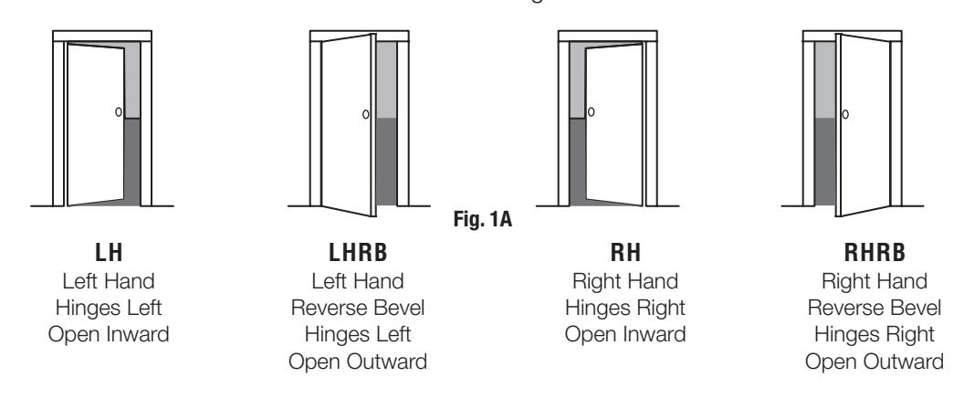
- Handing (RH/RHR/LH/LHR) must be specified, but is easily field-reversible without opening the lock case.
- Case 12 gauge heavy duty wrought steel
- Lock furnished for 1-3/4" doors. For other thicknesses, consult factory.
- Outside lever controlled by any combination of contactless reader. Inside lever retracts both latch and deadbolt.
- May be used for indoor and outdoor applications.
- ANSI/BHMA A156.25 Listed Grade 1 Compliant
Electronic Specifications
HID® multiCLASS SE® technology offers support for the following credentials:
High Frequency (13.56 MHz)
- HID iCLASS®
- HID iCLASS SE® (SIO-enabled)
- HID iCLASS Seos<sup>™</sup>
- HID MIFARE® SE
- HID DESFire EV1 SE
- HID MIFARE® Classic
- DESFire EV1
- PIV/PIV-I**
**(40-bit BCD, 64-bit BCD, 75 bit, 128-bit or 200-bit outputs)
Low Frequency (125 kHz):
HID Prox®
NFC & BLE-enabled mobile phones
- HID Mobile Access® (BLE & NFC)
- Apple Wallet Seos or DESFire® (NFC)
-
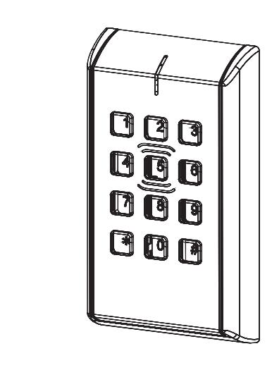
Optional keypad:
- PIN-only usage or dual authentication*
- Multiple time zone and holiday access scheduling
- First-in unlock or automatic unlock configuration, based on specified time schedule
- 10,000 per lock; 10,000 event audit trail
- · Privacy button
- Wi-Fi (IEEE 802.11 b/g/n)
- PoE (IEEE 802.3af)
Power requirements:
- Alkaline AA Batteries: 9V. 300mA
- PoE 55VDC, 90mA
- Optional Hard Power: 9-24VDC, 300mA
*For specific security information, please contact your local ASSA ABLOY Door Security Solutions sales consultant or call 800-810-WIRE.
Installation Instructions

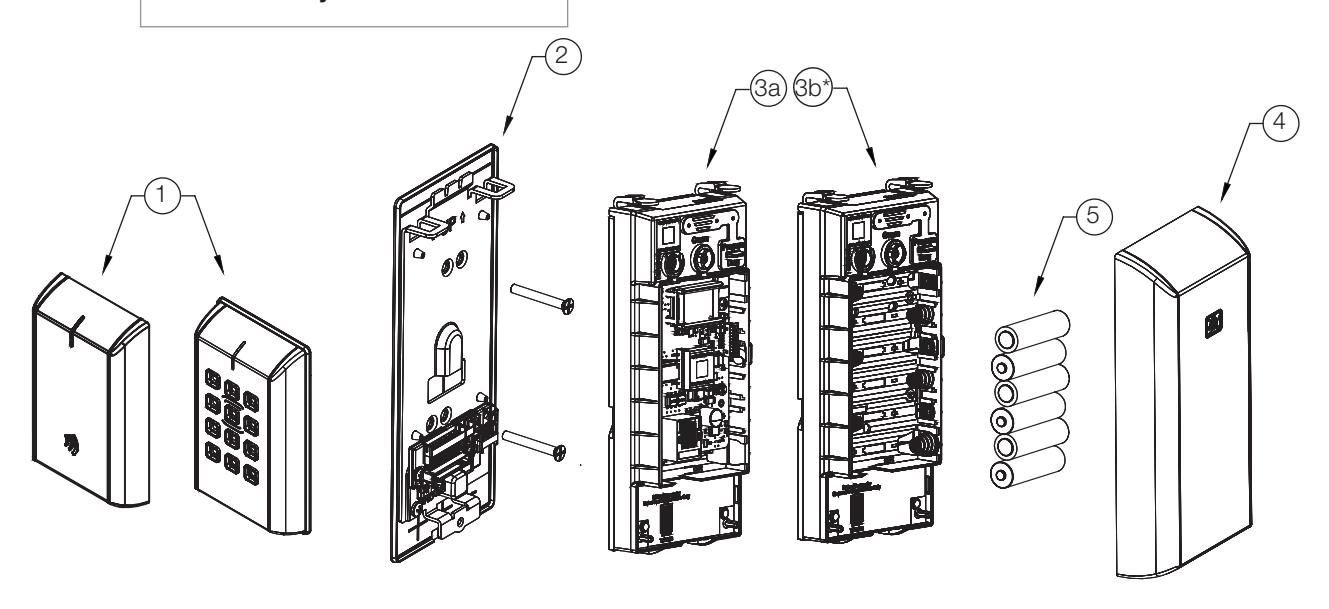
4 Parts Breakdown
Tools Required*:
- #2 Phillips screwdriver
- Flat blade screwdriver
- 1/8" Security Allen Wrench
*Additional list of tools required can be found in FE6600 and BL6600 Installation Instructions (FM440) See Section 5 Lock Installation
| ITEM No. | DESCRIPTION | |
|---|---|---|
| 1** | Outside Escutcheon Assembly | |
| 2 | Inside Mounting Plate Assembly (includes Gasket) | |
| 3a | PoE Controller Assembly | |
| 3b | Wi-Fi Controller Assembly* (batteries included) | |
| 4 | Inside Escutcheon Assembly with Privacy Button | |
| 5 | AA alkaline batteries (6) | |
** Consult catalog for electronic replacement part numbers
IN120 / IN220
FE6600/BL6600/MP6600 Series Multi-point Lock
Installation Instructions

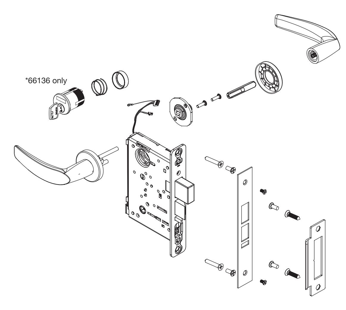
4 Parts Breakdown continued (Continued)
For mechanical parts listing refer to FE6600/BL6600/MP6600 Parts Manuals 45499 & 45611
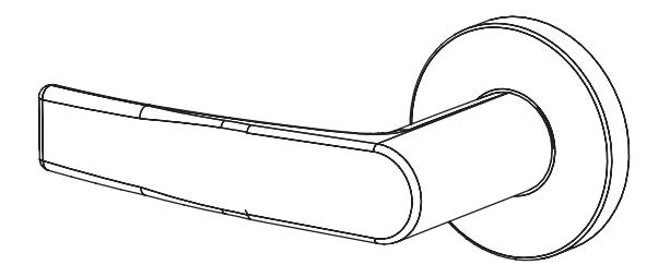
| Reference Catalog For Available Lever Styles | |||
| Reference Catalog For Available Rose Styles | |||
| Lock Body | MP66136-Trim-Finish-Hand-IN120 | Multipoint lock w/ deadbolt & w/ cylinder, fail safe / fail secure | 1 |
| FE66136-Trim-Finish-Hand-IN120 | FEMA hurricane-rated multipoint lock w/ deadbolt & w/ cylinder, fail safe / fail secure | 1 | |
| BL66136-Trim-Finish-Hand-IN120 | Blast-rated multipoint lock w/ deadbolt & w/ cylinder, fail safe / fail secure | 1 | |
| MP66135-Trim-Finish-Hand-IN120 | Multipoint lock w/ deadbolt & w/out cylinder, fail safe / fail secure | 1 | |
| FE66135-Trim-Finish-Hand-IN120 | FEMA hurricane-rated multipoint lock w/ deadbolt & w/out cylinder, fail safe / fail secure | 1 | |
| BL66135-Trim-Finish-Hand-IN120 | Blast-rated multipoint lock w/ deadbolt & w/out cylinder, fail safe / fail secure | 1 | |
| Cylinder* | 66136 only | 1 | |
Installation Instructions

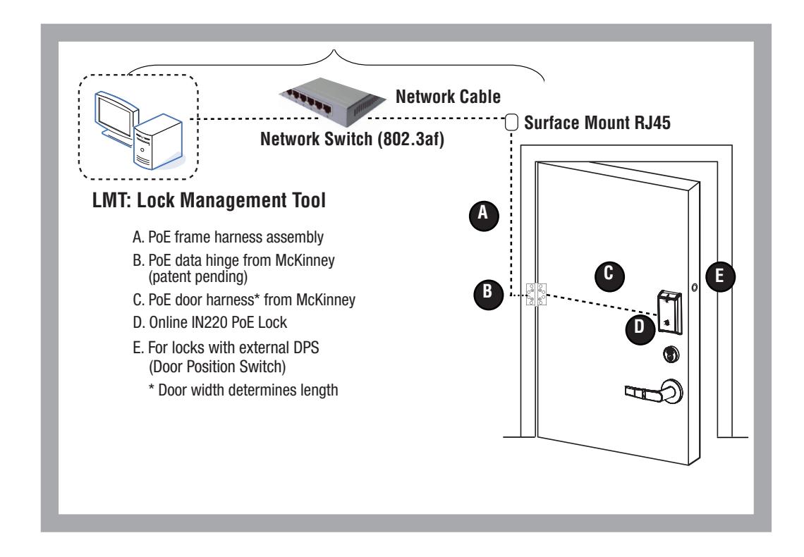
5 IN220 (PoE) Wiring & Installation
Overview: Corbin Russwin IN220 PoE Typical Application
Installation Instructions

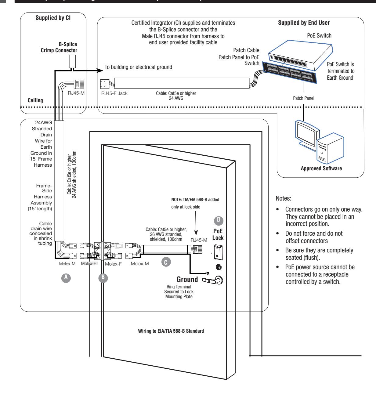
5 IN220 (PoE) Wiring & Installation (Continued)
ASSA ABLOY
Installation Instructions
5
IN220 (PoE) Wiring & Illustration (Continued)
a
Frame Harness Installation
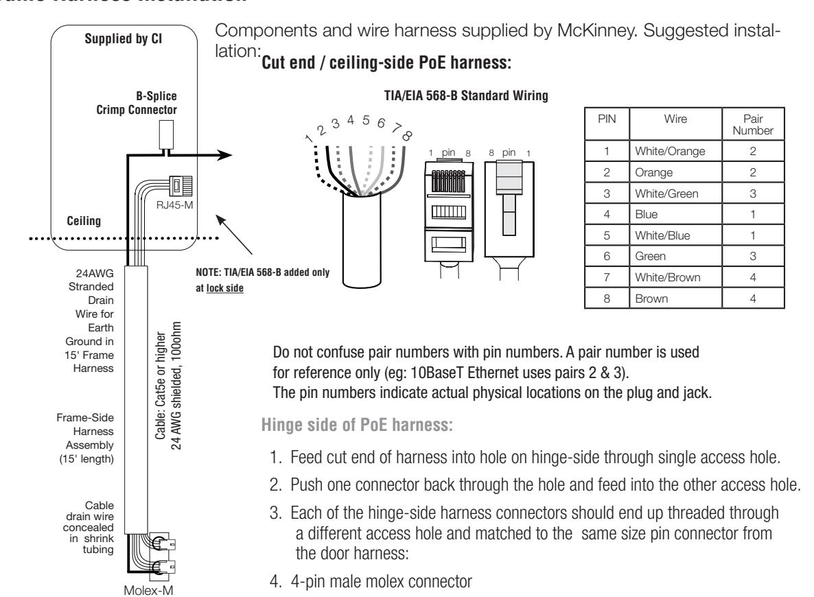
5. 6-pin male molex connector with ground wire
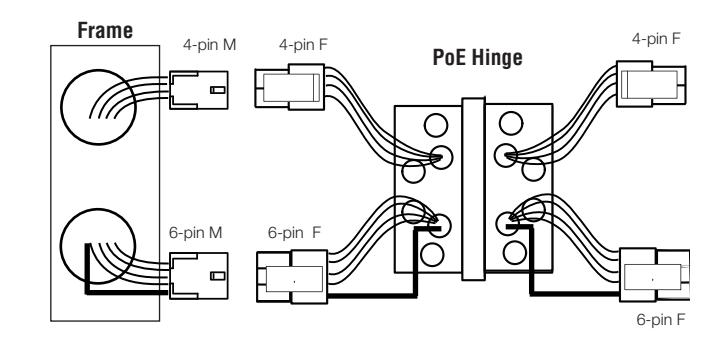
PoE Data Hinge
b
- Hinge-side harness connectors:
- 4-pin female molex connector
- 6-pin female molex connector with ground wire
- Lock-side harness connectors:
- 4-pin female molex connector
- 6-pin female molex connector with ground wire
Installation Instructions
5 IN220 (PoE) Wiring & Illustration, continued
c PoE Door Harness
Order of installation may vary. Refer to appropriate sections for instructions.
Hinge-side harness connectors:
- 4-pin male Molex connector
- 6-pin male Molex connector with ground wire
Lock-side harness connectors:
- Ring terminal
- Male RJ45 connector (crimped after cable is fed through door)
Notes:
Connectors go on only one way. They cannot be plugged to incorrect position.
Do not force and do not offset connectors.
Be sure they are completely seated (flush).
IN220 PoE Lock
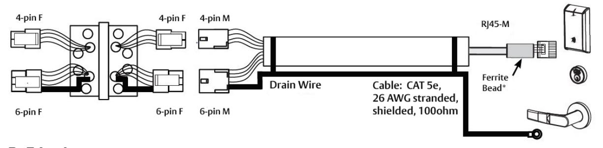
d PoE Lock
Order of installation may vary.
Refer to appropriate sections for instructions.
- 1. Prop door open
- 2. Using the ring terminal, carefully route the assembly through the door channel toward lock.
Note: Do not terminate PoE harness (with RJ45 M) until the cable has been routed through the door and the inside mounting plate assembly. See Section 6J - Installation of Connectors.
Russwin /2 ASSA ABLOY
Installation Instructions
6
Installation Instructions
а
Verify Hand and Bevel of Door
Stand on outside of locked door when determining door hand.
b
Door Preparation
Prior to installation, all holes must be free of burrs, debris and sharp edges.
Prepare door according to appropriate template. See www.intelligentopenings.com
- Door Manufacturer's Template: 4740
- FE6600 / BL6600 / MP6600 Series Installation Instructions: FM440 (ships with product)
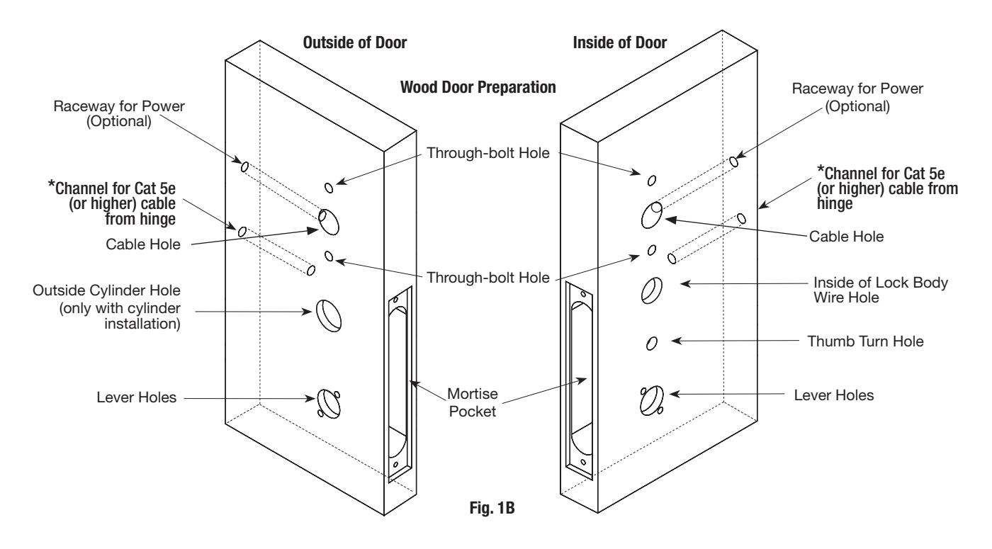
*See Section IN220 (PoE) Wiring and Installation
Installation Instructions

6 Installation Instructions (Continued)
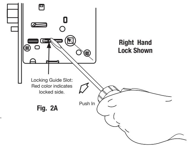
c Prepare Lock Body (if necessary)
1. Reverse Lock Hand
Red surface of locking piece must face the outside/locked side of door. To rotate locking piece (Fig. 2A):
- a. Position lock body with red surface of locking piece visible.
- b. Insert blade type screwdriver into locking piece slot to rotate locking piece toward back of lock body.
- c. Rotate the locking piece 180° until RED surface is on opposite side.
Note: Red indicates locked side (outside).
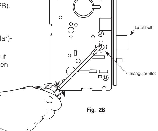
2. Reverse Latch Hand
Beveled surface of latch must face strike (Fig. 2B).
The deadlatch is self adjusting.
To change hand of latchbolt:
Copyright © 2019-2021 ASSA ABLOY Access and Egress Hardware Group, Inc. All rights reserved. Reproduction in whole or in part without the express written permission of ASSA ABLOY Access and Egress Hardware Group, Inc. is prohibited.
- a. Insert screwdriver into spade (triangular) shaped slot.
- b. Rotate screwdriver 90º to push latch out until back of latch clears lock front; then rotate latch 180º.
Latch will then re-enter lock body.
Note: Latch cannot be unscrewed.
FM455 04/21
Installation Instructions
6 Installation Instructions (Continued)
d Install Multi-Point Lock (FE6600 Series)

IMPORTANT: Read the following before continuing with installation !
Please refer to FM440 FE6600 & BL6600 MultiPoint Lock Installation Instructions (Fig. 3) before continuing with this installation.
Fig. 3
For installation assistance contact Corbin Russwin
Installation Instructions
6 Installation Instructions (Continued)
e Assemble Outside Trim
- 1. With outside lever horizontal, insert the mounting posts through outside of door and lock body.
- 2. Make certain the lever spindle is properly engaged inside the lock body (See Figure 4).
- 3. On the inside of the door, insert spindle into square hole of mortise lock (See Figure 4).
- 4. Slide inside adapter and plate assembly over spindle and secure with (2) 8-32 X 5/8" Phillips oval head and lock washer machine screws.
NOTE: For FE6600/BL6600/MP6600 Muséo levers, ensure that position of set screw hole on inside adapter is oriented to match location of hole in inside lever handle.
The slot in the spindle must face away from door (See Figure 4), and is oriented to match location of hole in inside lever handle.
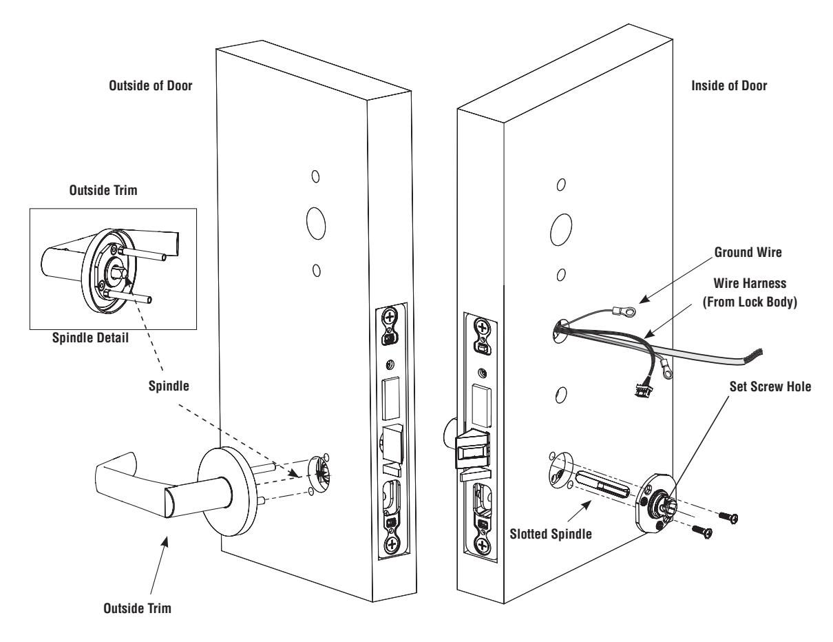
Fig. 4
For installation assistance contact Corbin Russwin
Installation Instructions
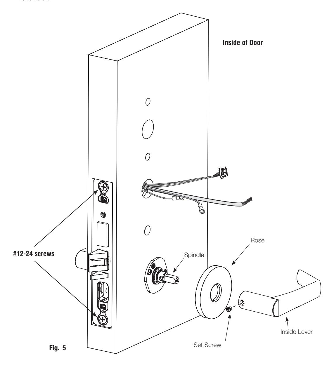
6 Installation Instructions (Continued)
f Install Inside Rose and Inside Lever Assembly
- 1. Place inside rose flush against door surface and rotate first counter-clockwise to seat the threads, then clockwise to securely tighten.
- 2. Slide lever onto spindle until fully seated. Be sure handle is horizontal and facing the hinge side of the door. Push lever onto spindle so minimum gap is visible.
- 3. Tighten the set screw securely with a T20 Torx® driver.
- 4. Finish securely tightening (2) #12-24 lock body screws.
- 5. Before closing the door, test that the lever is functional and ensure smooth operation of the latchbolt.
16
Installation Instructions
6 Installation Instructions (Continued)
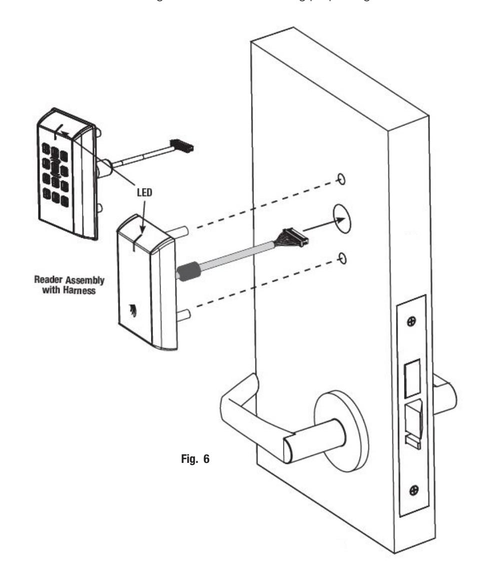
g Outside Reader Installation
- 1. Orient the reader so the LED lens is at the top.
- 2. Feed the reader harness through the door (from outside to inside).
- 3. Install reader to the outside of the door by aligning mounting posts with the door preparation holes. Hold the reader flush against door while ensuring proper alignment.
Installation Instructions
6 Installation Instructions (Continued)
h Outside Reader Installation, continued
- 4. Next feed the cables/connectors through the inside mounting assembly (and gasket if required*).
- 5. Secure the mounting assembly while ensuring proper alignment of outside reader and tighten the (2) through-bolts on the inside of the door to secure the reader (See figure below). IMPORTANT: Do not run wires through bottom hole in plate. It will damage wires and the controller connector. Route wires around flange, do not route wires through the flange hole (See figure detail below).
- 6. Secure ground lug(s) with #6-32 machine screw.
If installing with gasket; separate gasket from mounting plate to feed cables/connectors through holes as indicated.
Once cables/connectors are fed through, reattach gasket to mounting plate.
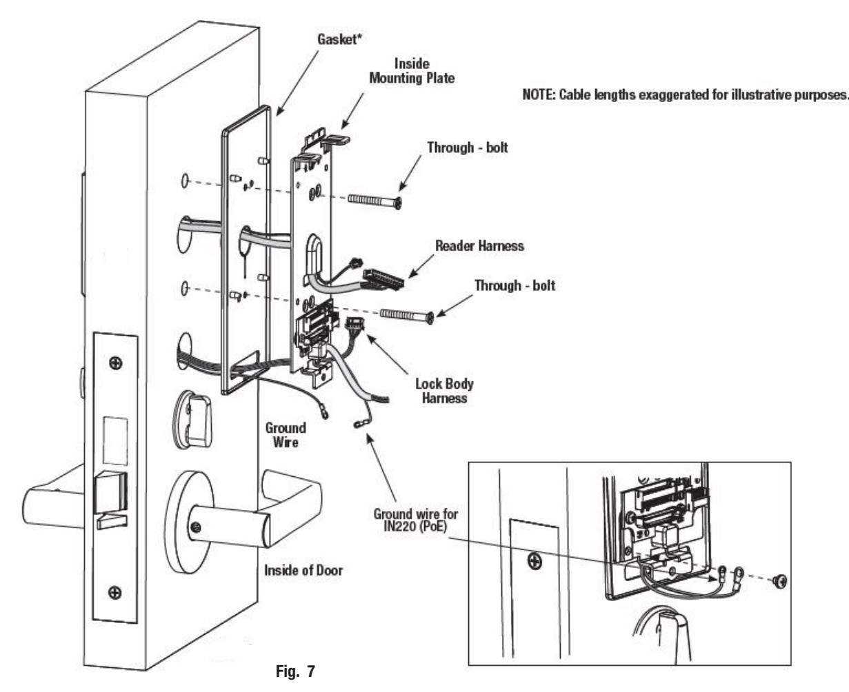
* Gasket is required for outdoor installations.
Installation Instructions
6 Installation Instructions (Continued)
i Installation of Connectors

Do not touch or allow debris to enter connector contacts. Cover the connectors with the silicone dielectric compound (grease). See Figure 10A.
- 1. Snip the end of the packet to dispense the grease. The supplied tube contains 5 grams of grease (Fig. 8A).
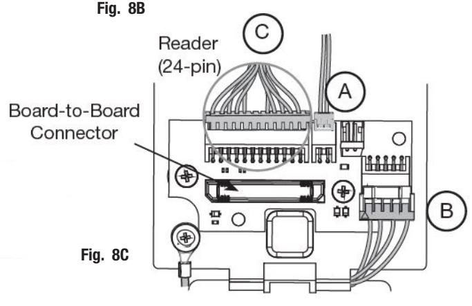
- 2. Evenly distribute the grease over the connector pins and contacts, wiping away any excess (See Figure 8B). Do not overfill or over apply. The full application requires approximately 2.5 grams.
- 3. Important: Do not run wires through the bottom hole in the plate (See Figure 8B). It will damage the wires and the controller connector. Route wires around the flange. Do not route wires through the flange hole.
- 4. Secure the 4-pin DPS connector (A). See Figure 8C.
- 5. Secure the 10-pin lock body assembly connector (B). See Figure 8C.
- 6. Tuck the excess cable into the wire hole on the inside of the door.
- 7. Secure the mouting assembly while ensuring proper alignment of the outside reader and fully tighten the (2) through-bolts on the inside of the door to secure the reader and plate to the door.
- 8. Secure the 24-pin card reader connector (C). See Figure 8C.
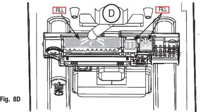
- 9 Ensure all openings on the back of the secured reader connector are covered completely with grease (D). See Figure 8D.
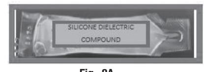
Fig. 8A
FM455 04/21
19
Russwin // ASSA ABLOY
Installation Instructions
6
Installation Instructions (Continued)
j
Installation of Connectors, continued
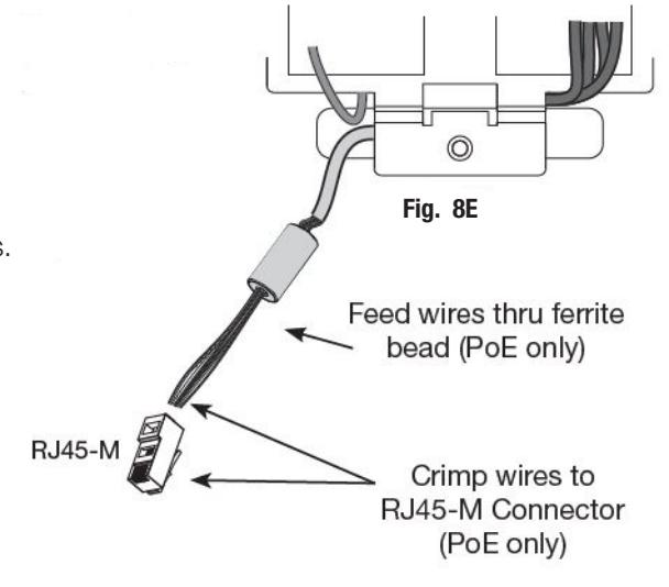
Note: If you are installing IN220 (PoE):
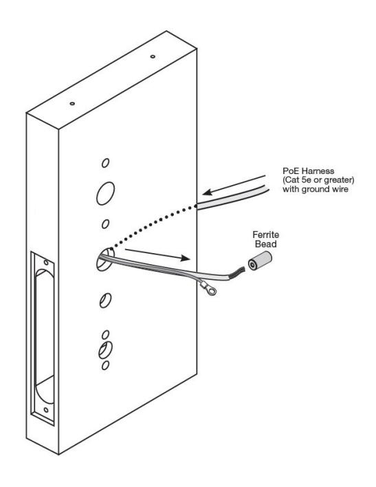
- 10. Pull 5-1/2" of Ethernet cable from hole. Strip the cable jacket back 3-1/2".
- 11. Separate (untwist) and straighten (8) Ethernet wires before carefully feeding through ferrite bead. See Figure 8E.
- Crimp RJ45 (male) connector on end of wires. For more detail, refer to Section 5A Frame Harness Installation.
k
Controller Installation

Before you install the controller, apply diaelectric grease to the connector located on the back of the controller. See Figure 9B. Do not allow debris to enter the connector contacts.
CAUTION - Do not allow debris to enter connector contacts.
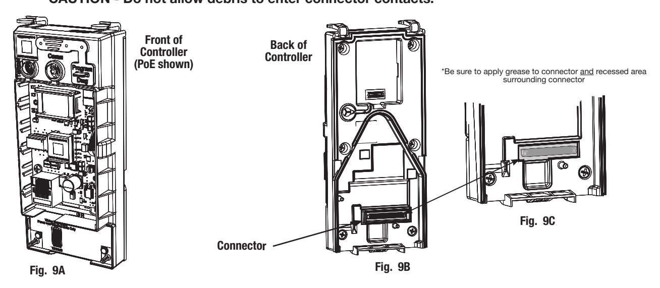
Apply the grease to the connector and the recessed area surrounding the connector.
Copyright © 2019-2021 ASSA ABLOY Access and Egress Hardware Group, Inc. All rights reserved. Reproduction in whole
or in part without the express written permission of ASSA ABLOY Access and Egress Hardware Group, Inc. is prohibited.
Installation Instructions
6 Installation Instructions (Continued)
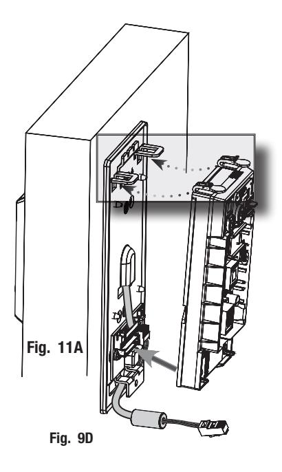
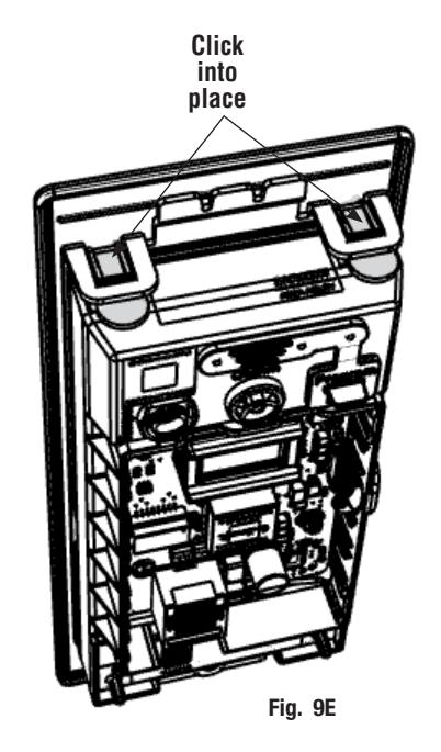
k Controller Installation, continued
- 1. Insert bottom tab of controller (ensure a clear path) into slot on mounting plate (Fig. 9D).
- 2. Align the board-to-board connectors (See Figure 9) by pivoting the controller toward the door until the two tabs on top click securely into place on the mounting plate (Fig. 9E).
CAUTION: To avoid possible damage to board-to-board connectors, care should be taken when securing controller to the mounting plate. If there is resistance when securing, detach the controller to determine the cause before re-attaching controller.
l Supplying Power to the Controller
Important - before inserting PoE plug into PoE connector, apply dielectric grease to top of plug, covering the pin area (Fig. 10A).
A. IN220 (PoE)
- 1. Once controller is securely in place, connect RJ45 male connector to female RJ45 port on controller board (Fig. 10A).
- 2. If power is enabled, LED will flash and lock motor will cycle.
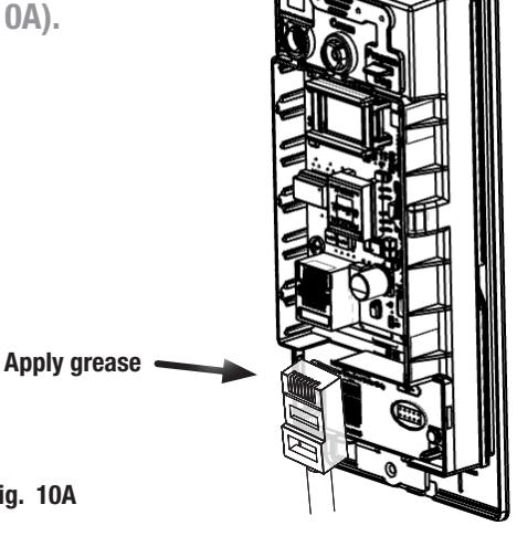
Fig. 10A
Installation Instructions
6 Installation Instructions (Continued)
l Supplying Power to the Controller, continued
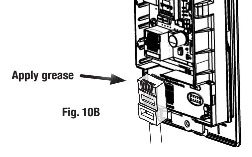
Important - before inserting PoE plug into PoE connector, apply dielectric grease to top of plug, covering the pin area (Fig. 12a).
A. IN220 (PoE)
- 1. Once controller is securely in place, connect RJ45 male connector to female RJ45 port on controller board (Fig. 12a).
- 2. If power is enabled, LED will flash and lock motor will cycle.
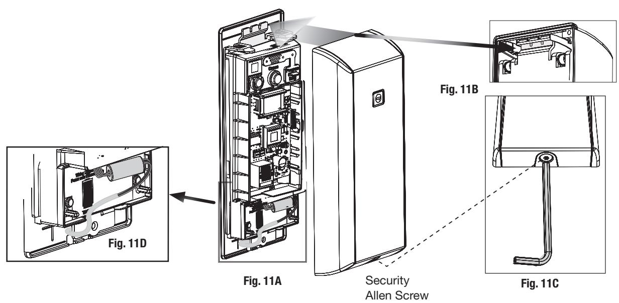
m Inside Cover Installation
- 1. Assemble cover by hooking the top edge on the inside mounting plate, taking care not to pinch gasket. The top edge goes between the plate and the gasket.
- 2. Carefully press the bottom of the cover toward the door without pinching any wires.
- 3. Secure the cover with a security allen wrench.
FM455 04/21
Installation Instructions

6 Installation Instructions (Continued)
m Install Shield
- a. Install shield (provided) over inside controller. (Figure 12)
- b. Drill and tap door for #8-32 machine screws (provided).
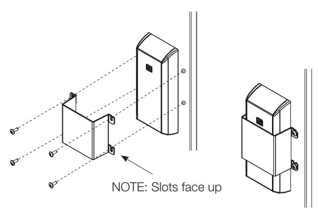
Fig. 12
IMPORTANT: Read the following before continuing with installation
Please refer to FM440 FE6600 & BL6600 MultiPoint Lock Installation Instructions before continuing with this installation if (optional) Dogging Indicator is being installed.
Installation Instructions

7 Operational Check
There should be no friction against lock case, wire harness or any other obstructions.
Try the inside lever:
Ensure it retracts latch and deadbolt (if installed).
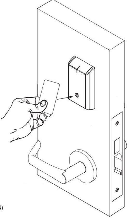
Use a valid credential* that has been set up with the Lock Configuration Tool to unlock outside lever and retract latch.
Refer to Lock Configuration Tool user manual (WFMN1) for information on how to configure and program locks.
NOTE: The credential should approach the inscription on the reader as indicated in the figure on the right to ensure that the credential is read properly.
Do not wave credential.
In all cases, perform the following checks:
- For units without a keypad, add card using LCT software* and test.
- For units with a keypad, add pin and card using LCT software* and test.
LED signaling:
- After using a valid credential a green flash followed by motor unlock indicates normal operation (lock unlocks).
- After using a valid credential a green flash followed by (4) beeps and (4) fast purple flashes – indicates low power. Check the input voltage.
- If the input voltage is low, disconnect lock from power source and check power source voltage. If power source voltage is correct, inspect lock wiring for a possible short.
- If the lock loses power, it will flash rapid blue for approximately one minute. Lock will default to programmed fail safe or fail secure.
- After that, the lock will no longer be functional.
Copyright © 2019-2021 ASSA ABLOY Access and Egress Hardware Group, Inc. All rights reserved. Reproduction in whole or in part without the express written permission of ASSA ABLOY Access and Egress Hardware Group, Inc. is prohibited.
When you have completed the tests, close the door, ensuring latchbolt fully extends into strike plate without binding.

Corbin Russwin 225 Episcopal Road Berlin, CT 06037 USA Phone: 800-543-3658