Corbin Russwin IN100 Series with PED5000 Series Exit Devices Installation Instructions_FM592
Open the original PDF document
View PDFInstallation Instructions


Attention Installer:
Please read these instructions carefully to prevent missing important steps.
Improper installations may result in damage to the lock and void the factory warranty.
The accuracy of the door preparation is critical for proper functioning and security of this lock.
Misalignment can cause premature wear and a lessening of security.
For specific security information, please contact your local ASSA ABLOY Door Security Solutions sales consultant or call 800-810-9473.

Table of Contents
| 1 | Warning | 3 |
|---|---|---|
| 2 |
Product & Technical Specifications
|
4 |
| 3 | Product Illustrations | 5 |
| Installation Instructions for: | ||
| 4 | PED5200 Rim Exit Device | 10 |
| 5 | PED5600 Mortise Exit Device | 15 |
| 6 | PED5800 Concealed Vertical Rod Exit Device (EA Option) | 21 |
| 7 | PED5400 Surface Vertical Rod Exit Device (EA Option) | 26 |
| 8 | IN100 Installation | 30 |
| 9 | Operational Check | 33 |
| 10 | Communication Hub LED Indications | 34 |
| 11 | Lock LED Indications | 35 |
| 12 | Lock Self-Test LED Indications | 36 |
| 13 | Lock Busy LED Indications | 37 |

1 Warning
Changes or modifications to this device not expressly approved by ASSA ABLOY could void the user's authority to operate the equipment.
FCC:
This equipment has been tested and found to comply with the limits for a Class B digital device, pursuant to Part 15 of the FCC Rules. These limits are designed to provide reasonable protection against harmful interference in a residential installation. This equipment generates, uses, and can radiate radio frequency energy and, if not installed and used in accordance with the instructions, may cause harmful interference to radio communications. However, there is no guarantee that interference will not occur in a particular installation. If this equipment does cause harmful interference to radio or television reception, which can be determined by turning the equipment off and on, the user is encouraged to try to correct the interference by one or more of the following measures:
- Reorient or relocate the receiving antenna.
- Increase the separation between the equipment and receiver.
- Connect the equipment into an outlet on a circuit different from that to which the receiver is connected.
- Consult the dealer or an experienced radio/TV technician for help.
Innovation, Science and Economic Development Canada:
Under Innovation, Science and Economic Development Canada regulations, this radio transmitter may only operate using an antenna of a type and maximum (or lesser) gain approved for the transmitter by Industry Canada. To reduce potential radio interference to other users, the antenna type and its gain should be so chosen that the equivalent isotropically radiated power (e.i.r.p.) is not more than that necessary for successful communication. Conformément à la réglementation d'Innovation, Sciences et Développement économique Canada, le présent émetteur radio peut fonctionner avec une antenne d'un type et d'un gain maximal (ou inférieur) approuvé pour l'émetteur par Industrie Canada. Dans le but de réduire les risques de brouillage radioélectrique à l'intention des autres utilisateurs, il faut choisir le type d'antenne et son gain de sorte que la puissance isotrope rayonnée équivalente (p.i.r.e.) ne dépasse pas l'intensité nécessaire à l'établissement d'une communication satisfaisante.
General Regulatory Compliance:
This device contains license-exempt transmitter(s)/receiver(s) that comply with Innovation, Science and Economic Development Canada's license-exempt RSS(s). Operation is subject to the following two conditions: (1) this device may not cause interference, and (2) this device must accept any interference received, including interference that may cause undesired operation of the device.
Ce dispositif contient des émetteurs/réceptuers exemptés de licence conformes aux RSS d'Innovation, Sciences et Développment économique Canada. L'opération est sujette aux deux conditions suivantes: (1) ce dispositif peut ne pas causer l'interférence, et (2) ce dispositif doit accepter n'importe quelle interférence reçue, y compris l'interférence qui peut causer l'opération peu désirée a le dispositif.
This equipment complies with FCC and IC radiation exposure limits set forth for general population (uncontrolled environment). This device must not be co-located or operating in conjunction with any other antenna or transmitter.
Cet équipement est conforme aux limites d'exposition aux radiations de la FCC et IC définies pour la population générale (environnement non contrôlé). Cet appareil ne doit pas être co-localisé ou fonctionner en conjonction avec une autre antenne ou un autre émetteur.

This product can expose you to lead which is known to the state of California to cause cancer and birth defects or other reproductive harm. For more information go to: www.P65warnings.ca.gov.
Ce produit peut vous exposer au plomb qui, dans l'état de la Californie, est reconnu pour causer le cancer, des anomalies congénitales ou d'autres problèmes de reproduction.
Pour plus d'informations, visitez: www.P65warnings.ca.gov.
Any retrofit or other field modification to a fire rated opening can potentially impact the fire rating of the opening, and SARGENT Manufacturing makes no representations or warranties concerning what such impact may be in any specific situation. When retrofitting any portion of an existing fire rated opening, or specifying and installing a new fire-rated opening, please consult with a code specialist or local code official (Authority Having Jurisdiction) to ensure compliance with all applicable codes and ratings.

To avoid possible damage from electrostatic discharge (ESD), some basic precautions should be used when handling electronic components:
- Minimize build-up of static by touching and/or maintaining contact with unpainted metal surfaces such as door hinges, latches, and mounting plates especially when mounting electronic components such as readers and controllers onto the door.
- Leave components (reader and controller) protected in their respective anti-static bags until ready for installation
- Do not touch pins, leads or solder connections on the circuit boards

2 Product & Technical Specifications
Operating temperature: -13°F (-25°C) to 151°F (66°C) Humidity: < 85% non-condensing
Input Power: DC 9V, 1.5A (6 AA alkaline batteries) Optional hard-power 12-24VDC, 1.0A
Reader with multiCLASS SE® technology offers support for the following credentials:
High Frequency (13.56 MHz)
HID iCLASS®
HID iCLASS SE® (SIO-enabled)
HID iCLASS® Seos™
HID MIFARE® SE
HID DESFire® EV1 SE
MIFARE Classic
DESFire EV1
DESFire EV2/EV3 (EV1 Compatibility)
Low Frequency (125 kHz)®, AWID
EM4102
PIV/PIV-I
40-bit BCD, 64-bit BCD, 75 bit, 128-bit or 200-bit outputs
NFC & BLE-enabled Mobile Phones:
HID Mobile Access® (BLE and NFC)
Apple Wallet Seos (NFC)
Apple Wallet DESFire® (NFC)
Google Wallet DESFire® (NFC)
NOTE: reference IN100 catalog for complete list of certifications
UL NOTES:
UL Listed to UL294 Indoor Dry Use, 32°F (0°C) to 120°F (49°C ), 93% Relative Humidity at 90°F (32°C) installed in accordance with NFPA70, National Electrical Code.
ULC-60839-11-1 Listed Security Grade 2 Indoor Dry Use, 32°F (0°C) to 120°F (49°C ), 93% Relative Humidity at 90°F (32°C), IP4X installed in accordance with CSA C22.1, Canadian Electrical Code.
UL 294 Access Control Ratings:
Destructive Attack Level 1, Line Security Level 1, Endurance Level 4, Standby Power Level 1
Reader controller firmware version 3.14.x or greater
The electronic access control system shall not prohibit the free exit granted by other emergency systems (e.g. fire, environmental)
For Use with the separately Listed Model AH20, AH30 and AH40 HUBs

3 Product Illustrations
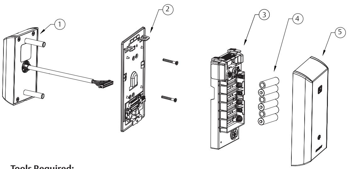
Tools Required:
- #2 Phillips screwdriver
- Flat blade screwdriver
- 1/8" Security hex key
- 7/64" Allen Wrench
See Parts Manual FM646 for part numbers
| ITEM No. | DESCRIPTION |
|---|---|
| 1 | Aperio Reader Assembly |
| 2 | Mounting Plate Assembly (includes gasket) |
| 3 | Aperio Controller |
| 4 | AA alkaline batteries (6) |
| 5 | Branded Battery Cover Assembly with Privacy Button |
FM592 09/23

33 / 34 Function x Trim x Lever Design
| ITEM | DESCRIPTION | REQ'D |
|---|---|---|
| 1 | Cylinder Assembly (Reference Catalog for Available Cylinders) | 1 |
| 2 | Lever (Reference Catalog for Available Styles) | 1 |
| 3 | Exit Trim With Cylinder | |
| Exit Trim Without Cylinder | ||
| Motor Assembly (Separate - not shown) | 1 | |
| 4 | Chassis Assembly | |
| Chassis Assembly (Fire Rated) | ||
| Chassis Assembly (Latch Guarding) | ||
| Chassis Assembly (Fire Rated Latch Guarding) | ||
| 5 | 1/4-20 x 2-3/8" Trim Screws | 2 |
| 6 | #10 x 1-1/4" Chassis Screws | 4 |
| #10-24 x 3/4" Chassis Screws | 4 | |
| 7 | #8-32 x 5/16" Cover Screws | 2 |
| #8-32 x 5/8" Cover Screws (rail side) | 2 | |
| 8 | Chassis Cover | 1 |
| Chassis Cover (With Guarding) | ||

33 / 34 Function x Trim x Lever Design
| ITEM | DESCRIPTION | REQ'D |
|---|---|---|
| 1 | Cylinder Assembly (Reference Catalog for Available Cylinders) | 1 |
| 2 | Lever (Reference Catalog for Available Styles) | 1 |
| 3 |
Exit Trim With Cylinder
1 |
|
| Exit Trim Without Cylinder | ||
| Motor Assembly (Separate - not shown) | ||
| 4 | Lock Body Assembly LHR | 1 |
| Lock Body Assembly RHR | ||
| Lock Body Assembly LHR (Non-Beveled Door) | ||
| Lock Body Assembly RHR (Non-Beveled Door) | ||
| 5 | Screw Pack | 1 |
| 6 | Chassis Assembly LHR | 1 |
| Chassis Assembly RHR | ||
| 7 | Screw Pack | 1 |
| 8 | Chassis Cover | 1 |
7

33 Function
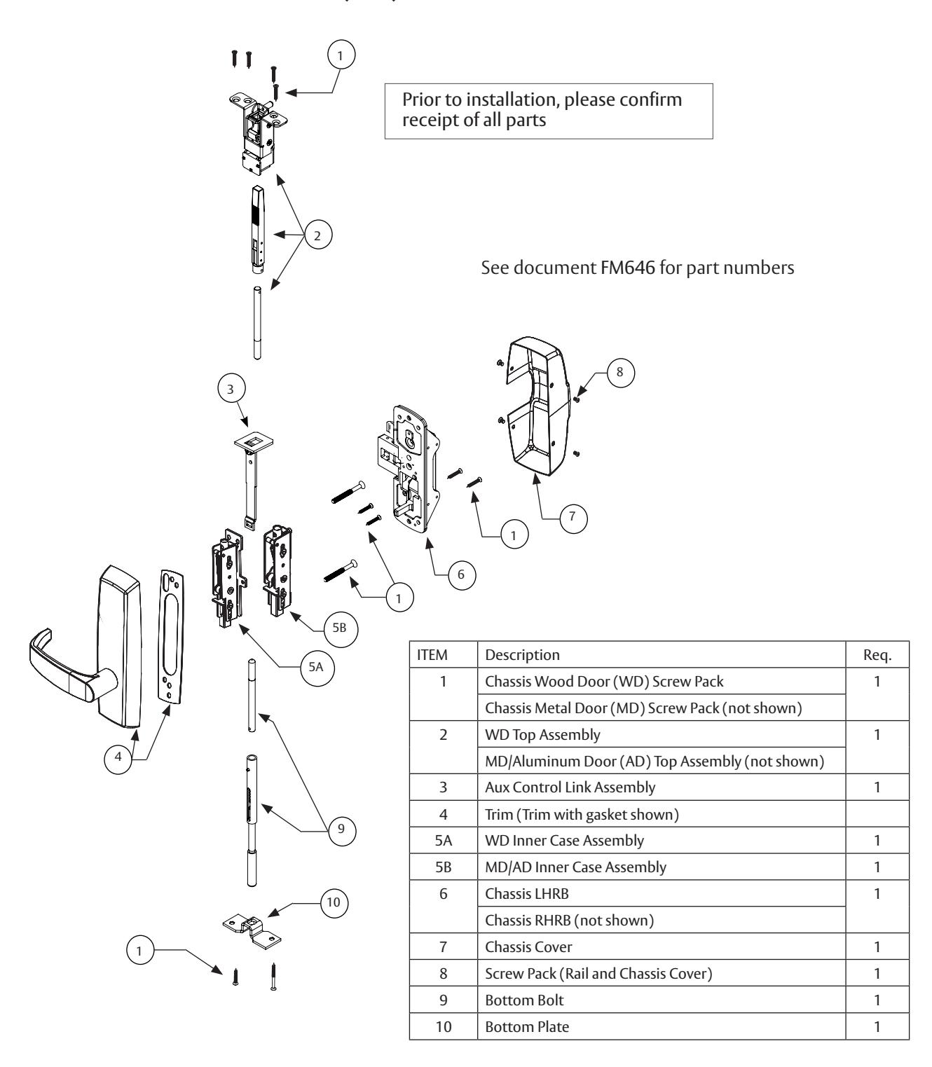
PED5800 Concealed Vertical Rod (CVR) Exit Device
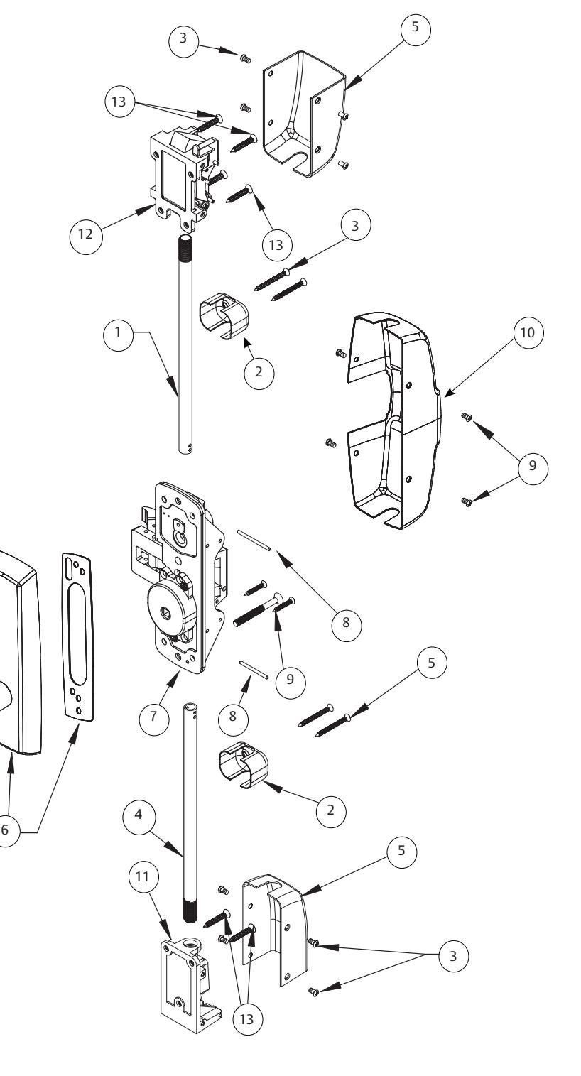
33 Function
PED5400 Surface Vertical Rod (SVR) Exit Device
| 1 | Top Rod (consult factory) | 1 |
| 2 | Guide for Rod | 2 |
| 3 | Screw Pack for Guide and Covers | 2 |
| 4 | Bottom Rod (consult factory) | 1 |
| 5 | Case Assembly Cover | 2 |
| 6 | Trim (Trim with gasket shown) | 1 |
| 7 | Chassis Assembly LHRB | 1 |
| Chassis Assembly RHRB | ||
| 8 | Rod Adjustment Pin | 2 |
| 9 | Screw Pack "B" | 1 |
| Screw Pack "A" | ||
| 10 | Chassis Cover | 1 |
| 11 | Bottom Case Assembly | 1 |
| 12 | Top Case Assembly | 1 |
| 13 | Screw Pack (Top and Bottom Cases) | 1 |

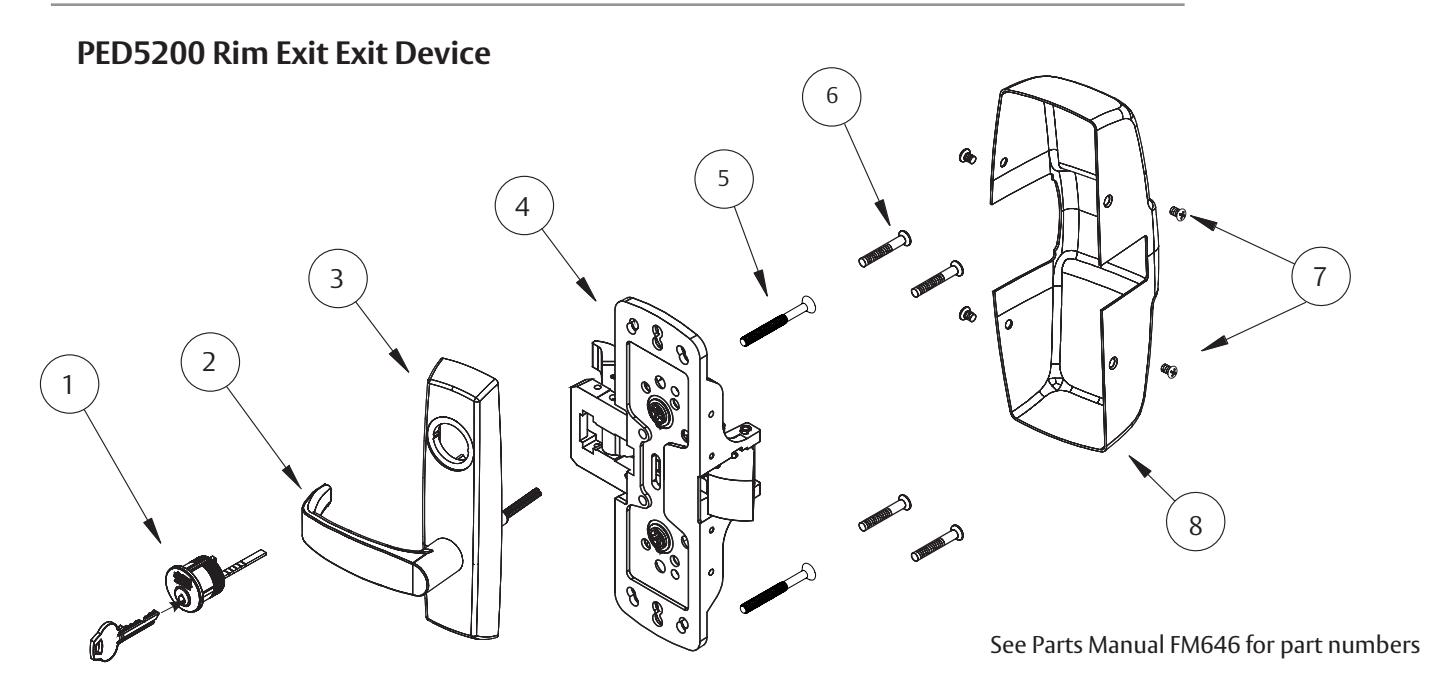
4 Installation Instructions for PED5200 Rim Exit Device
Prepare door.
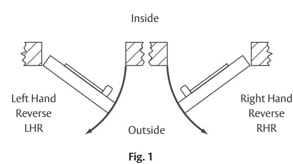
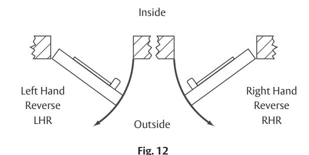
a. Verify hand and bevel of door. (Fig. 1)
NOTE: Stand on outside of locked door when determining door hand.
- b. Verify exit device is correct hand for door.
- c. Door should be fitted and hung.
- d. Verify product label.
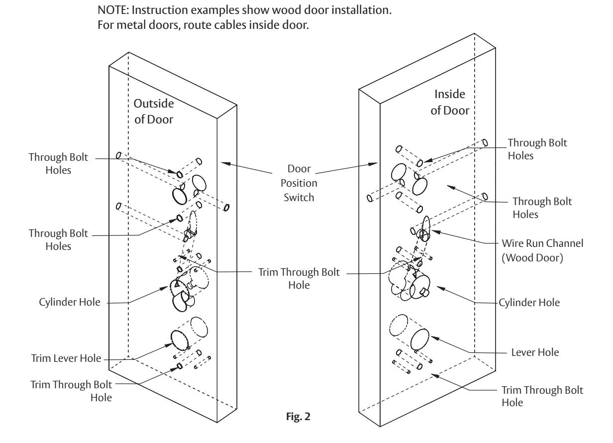
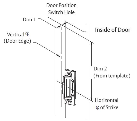
e. Mark and drill door. (Fig. 2)
- If mullion is used, install prior to installing hardware
- Doors should be pre-prepped (recommended)
Prior to installation, all holes must be free of burrs, debris and sharp edges.
Prepare door according to appropriate template (see website).
- Field Template (ships with product): MEFT18 ( MEFT26 for EA option)
- Door Manufacturer's Template (online): MEDT53
- Exit Device Installation Instructions: FM577


4 Installation Instructions for PED5200 Rim Exit Device (Continued)
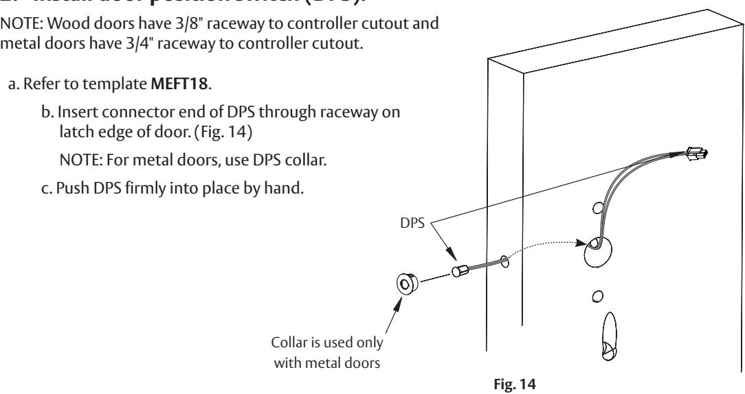
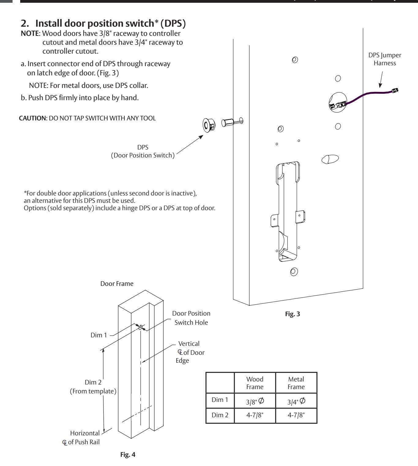
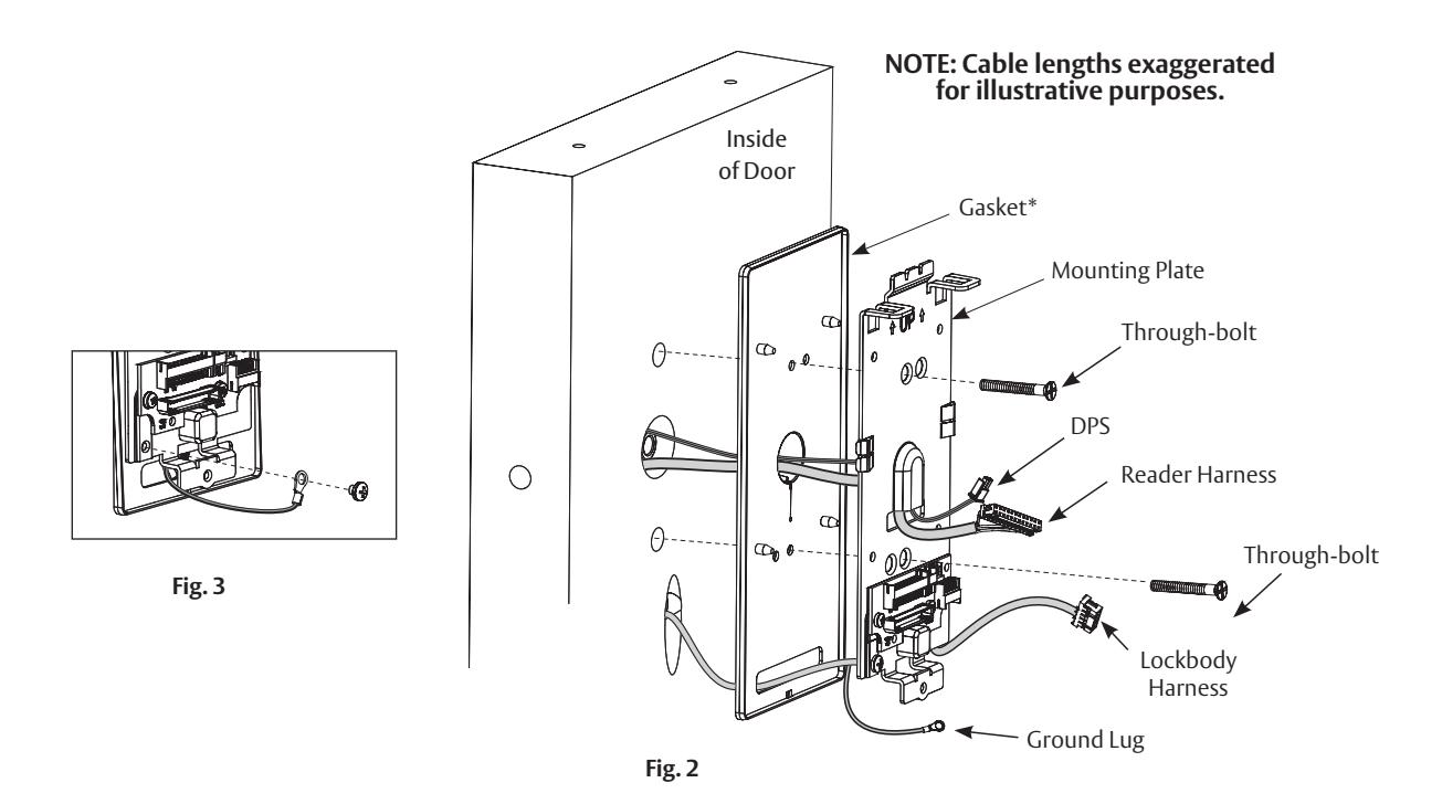
2. Install door position switch (DPS).
NOTE: Wood doors have 3/8" raceway to controller cutout
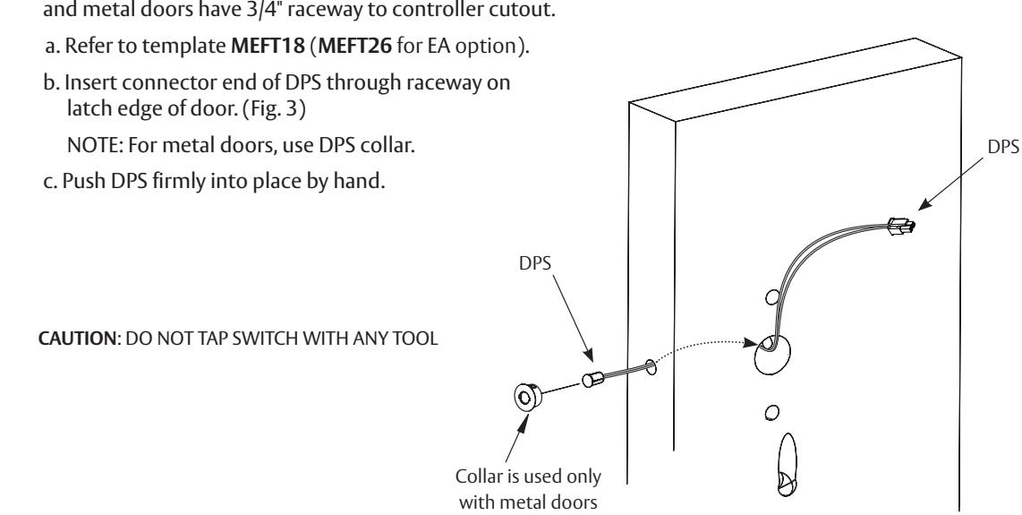
Fig. 3
Door Frame
|
Wood
Frame |
Metal
Frame |
|
|---|---|---|
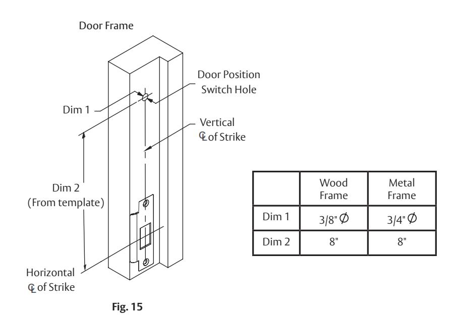
| Dim 1 | 3/8" | 3/4" |
| Dim 2 | 8-3/8" | 8-3/8" |
Fig. 4

4 Installation Instructions for PED5200 Rim Exit Device (Continued)
3. Mount exit device chassis.
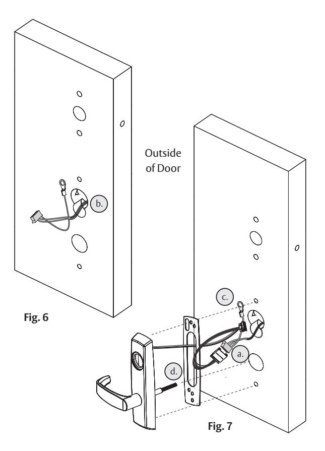
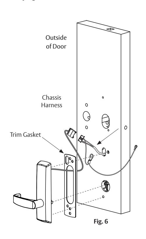
NOTE: Exit chassis harness consists of a 6-pin female connector and (2) ground wire terminals. (Fig. 5)
a. Feed 6-pin connector and larger ground lug straight through to outside of door. (Fig.s 5, 6)
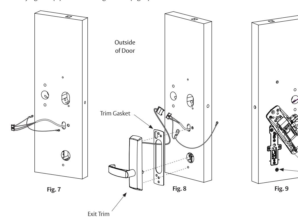
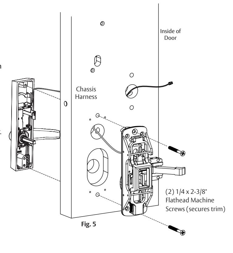
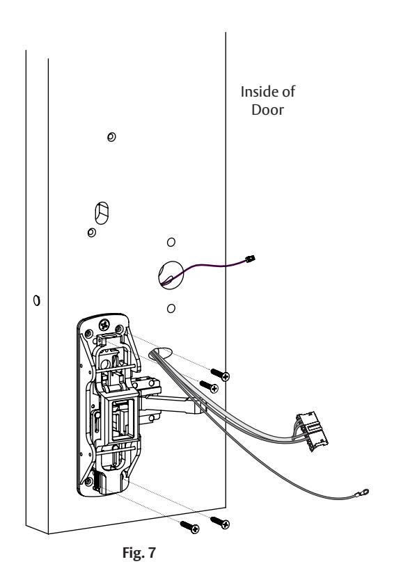
4. Mount exit trim. (Fig. 7)
NOTE: For exterior applications, use trim gasket as seal between trim escutcheon and outside door surface.
- a. Connect motor harness adapter to chassis harness connector.
- b. For wood doors: Route trim wire harness connector through cylinder hole, up and through wire run channel to controller cutout.
- For metal doors: Route trim wire harness through cylinder hole out controller cutout.
- c. Pass top trim mounting post through chassis harness ground lug.
- d. Ensure trim spindle engages lower hub of exit chassis.
- e. Partially tighten two (2) chassis through bolts.
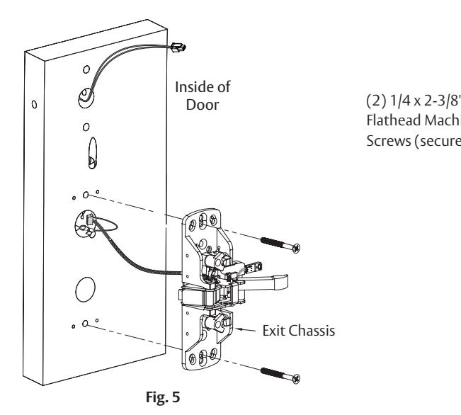
Flathead Machine Screws (secures trim)

For devices without cylinder, go to Step 6.
5. Install cylinder (Fig. 9)
a. While installing rim cylinder, support tail piece of cylinder, verifying its engagement with top hub of exit chassis.
NOTE: Be sure trim harness is clear of cylinder and tailpiece.
- b. Secure cylinder by through-bolting cylinder through exit chassis using two (2) #12-24 x 1-7/8" connecting screws (Fig. 10). DO NOT FULLY TIGHTEN UNTIL AFTER STEP 7.
- c. Verify that key retracts latchbolt.
6. Secure exit chassis (Fig.10)
To comply with UL certifications and for security:
a. Fasten exit chassis to door using four (4) #10 wood screws (for wood door) or four (4) #10-24 machine screws (for metal door). DO NOT FULLY TIGHTEN UNTIL AFTER STEP 7.
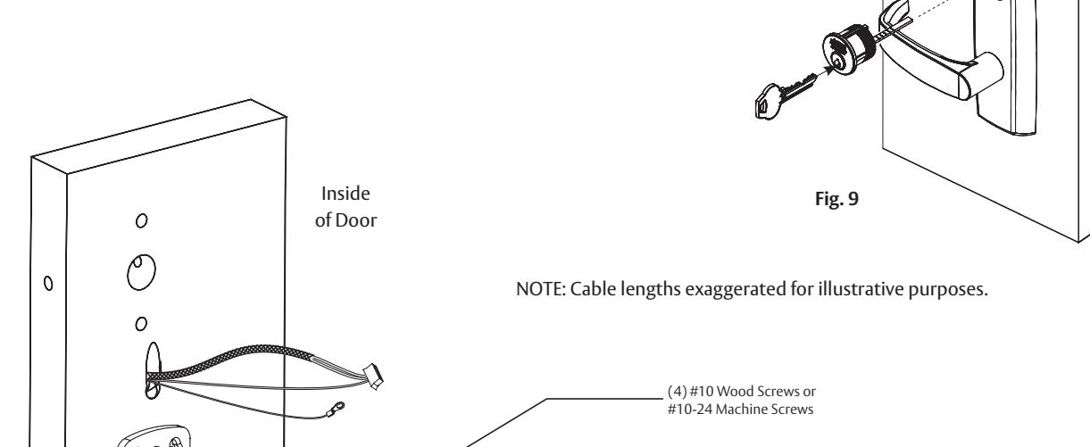
Fig. 10
(2) #12-24 x 1-7/8" Flat Head Screws
(Through-bolts Cylinder to Chassis)
Outside of Door

4 Installation Instructions for PED5200 Rim Exit Device (Continued)
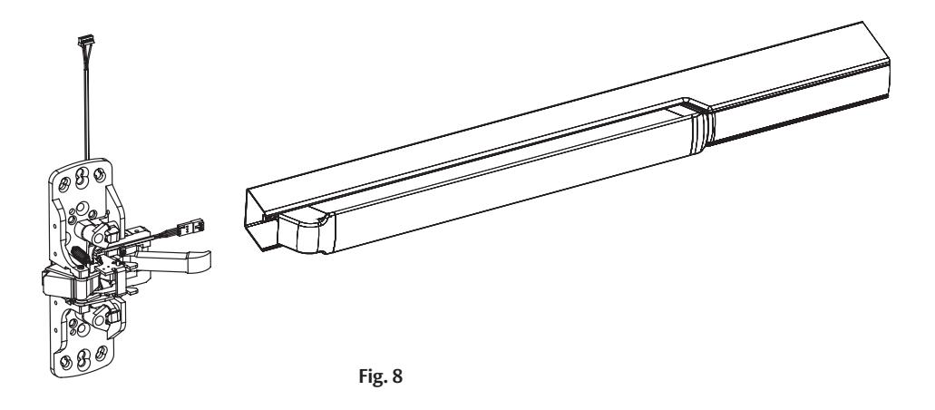
7. Install rail assembly (Fig. 11)
- a. Retrieve harness from end of rail. Harness has limited travel and can be damaged.
- b. Attach harness to female connector on chassis.
- c. Install rail and tighten chassis, trim, and cylinder screws. Attach end bracket per exit device instructions.
- d. Secure chassis cover to chassis using four (2) #8-32 x 5/16" and (2) #8-32 x 5/8" (rail side) oval head machine screws. Fig. 11 (2) #8-32 x 5/8" oval head machine screws (2) #8-32 x 5/16" oval head machine screws
Important Note: IN100 Rim Exit Installation Continues With Section 8

5
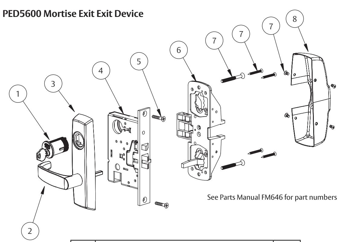
Installation Instructions for PED5600 Mortise Exit Device
1. Prepare door
a. Verify hand and bevel of door (Fig. 12).
NOTE: This exit device is handed and is not reversible.
- b. Door should be fitted and hung.
- c. Verify product label.
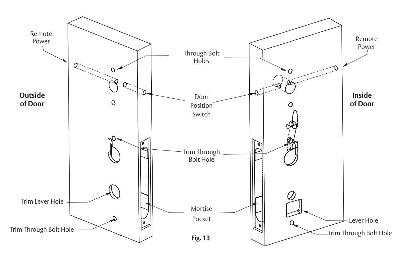
- d. Mark and drill door. (Fig. 13)
If using a mullion, install it prior to installing hardware.
- 1. Doors should be pre-prepped (recommended).
-
2. Prepare door according to appropriate template:
- Field template (ships with product): MEFT18
- Door manufacturers template (online): MEDT54
- Exit Device Installation Instructions: FM580
Note: Instruction examples show wood door installation.
For metal doors, route cables inside door.
2. Install door position switch (DPS).
IMPORTANT : DO NOT TAP SWITCH WITH ANY TOOL

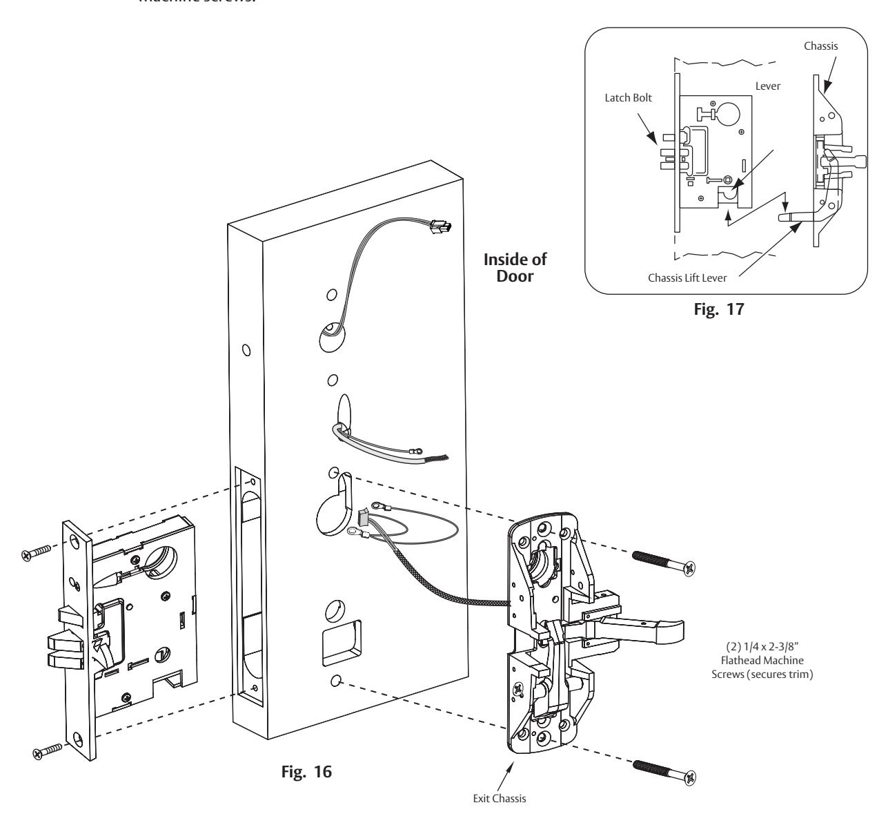
3. Mount mortise and exit device chassis.
a. Slide mortise lock into door and loosely secure with two (2) flat head screws.
NOTE: Exit chassis harness consists of a 6-pin female connector and ground wire/terminal. (Fig. 16)
b. Feed 6-pin connector and larger ground lug straight through to outside of door (Fig. 16, Fig. 17) while feeding smaller ground lug into wire hole, up through wire channel and out through inside of door. (Fig. 16)
CAUTION: Do not pinch wire harness.
c. Begin to secure exit chassis with through bolts to trim using two (2) 1/4 -20 x 2-3/8" flat head machine screws.

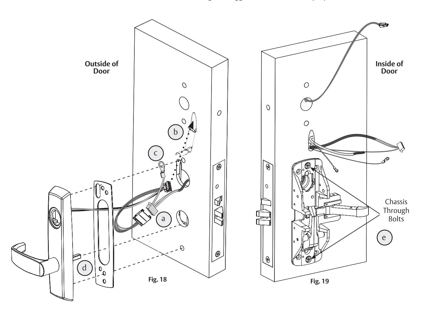
4. Position exit trim. (Fig. 18)
NOTE: For exterior applications, use trim gasket to seal between trim escutcheon and outside door surface.
- a. Connect motor harness adapter to chassis harness connector.
- b. For wood doors: Route trim wire harness connector through cylinder hole, up and through wire run channel to controller cutout.
- For metal doors: Route trim wire harness through cylinder hole out controller cutout.
- c. Pass top trim mounting post through chassis harness ground lug.
- d. Ensure trim spindle engages mortise lock body.
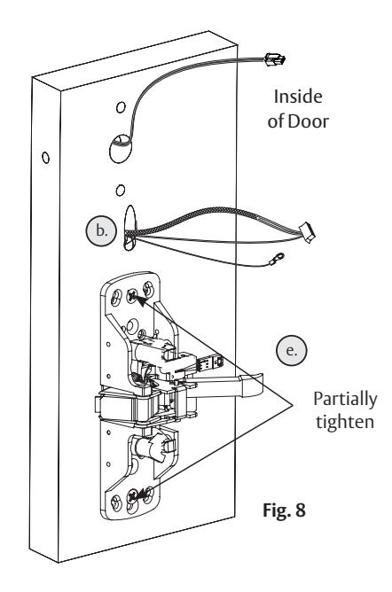
- e. Begin to secure chassis to trim by partially tightening two (2) chassis through bolts. (Fig. 19).
NOTE: DO NOT FULLY TIGHTEN AT THIS TIME
NOTE: Cable lengths exaggerated for illustrative purposes
Position cylinder so that the Corbin Russwin logo is right-side up Correct Incorrect Fig. 20A Fig. 20B 5. Install Cylinder For devices without cylinder, go to Step 6. a. Secure cylinder by threading into lockbody. b. After cylinder is installed, tighten cylinder lock screw (clockwise) through front of mortise lock. c. Verify that key retracts latchbolt. Outside of Door
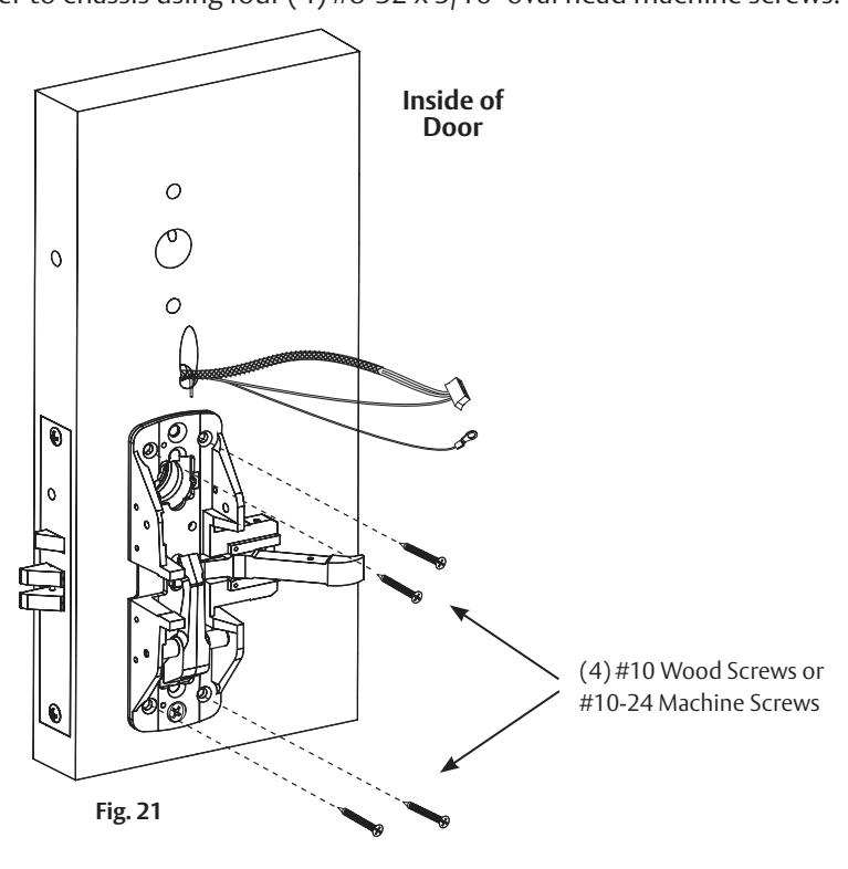
6. Secure Exit Chassis
To comply with UL certifications and for security:
- a. Fasten exit chassis to door using four (4) #10 wood screws (for wood door) or four (4) #10-24 machine screws (for metal door).
- b. Secure chassis cover to chassis using four (4) #8-32 x 5/16" oval head machine screws.

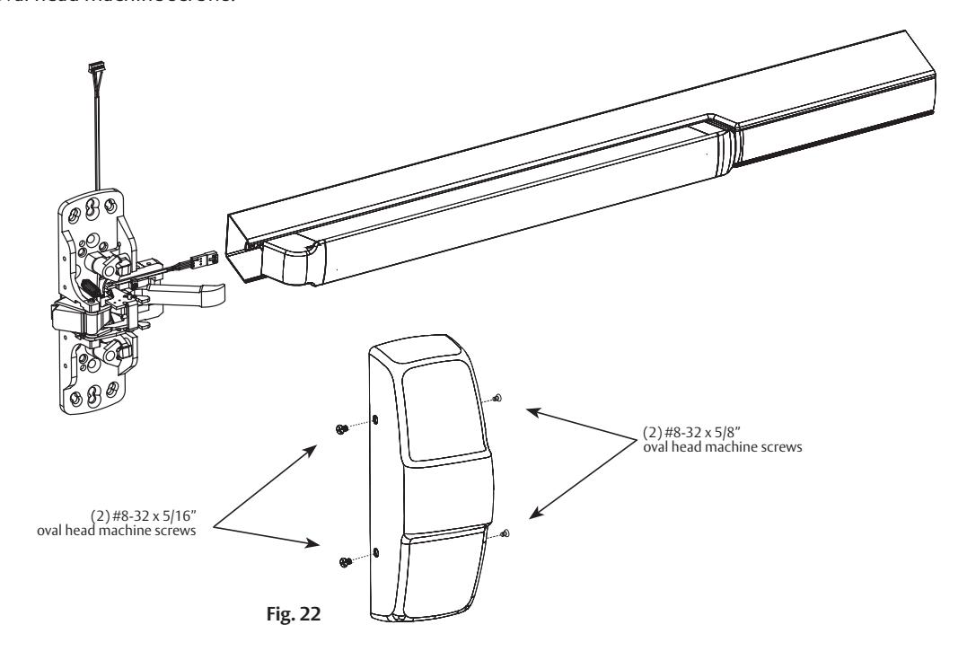
7. Install rail assembly. (Fig. 22)
- a. Retrieve harness from end of rail. Harness has limited travel and can be damaged.
- b. Attach harness to female connector on chassis.
- c. Install rail and tighten chassis and trim screws. Attach end bracket per exit device instructions.
- d. Secure chassis cover to chassis using four (2) #8-32 x 5/16" and (2) #8-32 x 5/8" (rail side) oval head machine screws.
Important Note: IN100 Mortise Exit Installation Continues With Section 8

1. Prepare door
a. Verify hand and bevel of door. (Fig. 1)
NOTE: Stand on outside of locked door when determining door hand.
- b. Verify exit device is correct hand for door.
- c. Verify product label.
- d. Mark and drill door. (Fig. 2)
permission of ASSA ABLOY Access and Egress Hardware Group, Inc. is prohibited.
- If mullion is used, install prior to installing hardware
- Doors should be pre-prepped (recommended)
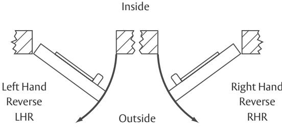
Fig. 1
Prior to installation, all holes must be free of burrs, debris and sharp edges.
Prepare door according to appropriate template (see website).
• Door Manufacturer's Template (online): MEDT68

3. Install Inner Case Assembly
- A. Wood Door (WD)
- 1. Install the inner case assembly with (2) #12 x 1" Phillips flathead screw (Fig. 5A).
- B. Metal Door (MD/AD)
- 1. Assemble rods to inner case.
- 2. Slide rod assembly into door and secure with #10-24 x 3/8" screw for top inner case assembly and #10-24 x 1/2" screw for bottom inner case assembly (Fig. 5B).
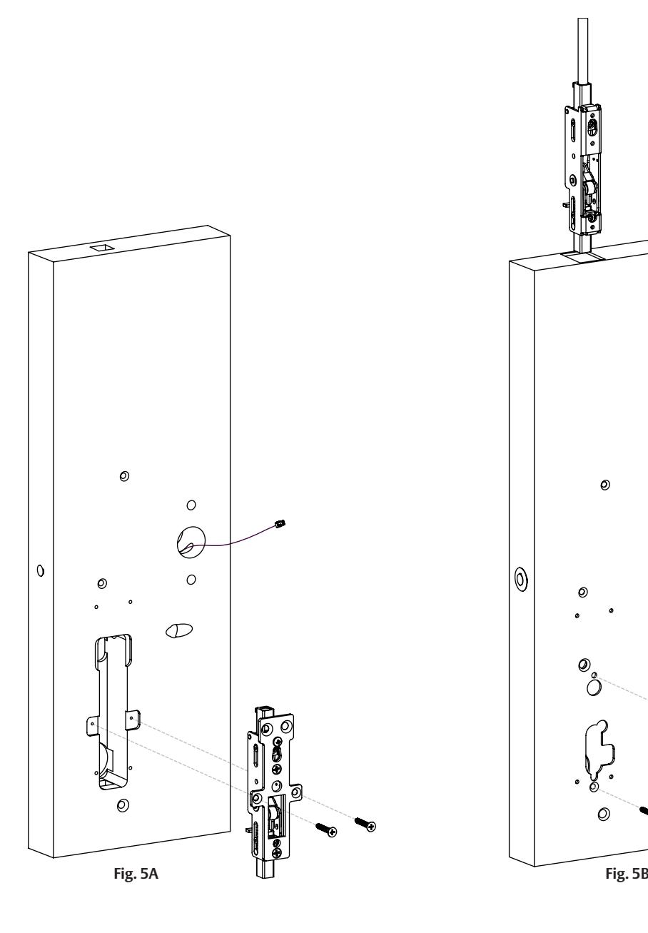
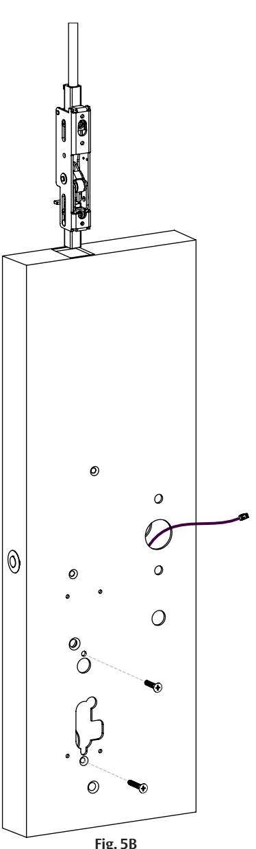
Inside of Door
Fully tighten
6 Installation Instructions for PED5800 Concealed Vertical Rod (CVR) Exit Device (EA Option)
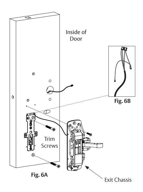
4. Mount exit device chassis.
a. Mount exit chassis loosely, using only the top left mounting screw. Screw should support the weight of the chassis but allow it to move freely while routing the wiring and mounting exit trim.
NOTE: Exit chassis harness consists of a 6-pin female connector and (2) ground wire terminals (Fig. 6B).
b. Feed 6-pin connector and larger ground wire terminal straight through to outside of door. (Fig. 6B, 7)
c. Insert (2) trim mounting screws (Fig. 6A).
5. Mount exit trim. (Fig. 8)
NOTE: For exterior applications, use trim gasket as seal between trim escutcheon and outside door surface.
- a. Connect motor harness adapter to chassis wire harness connector.
- b. For wood doors: Route trim wire harness connector through oval wire routing hole, up and through wire run channel to controller cutout.
For metal doors: Route trim wire harness through oval wire mounting hole and out controller cutout.
- c. Pass top trim mounting post through chassis harness ground lug.
- d. Fully tighten (2) trim mounting screws. (Fig. 9)
6. Secure exit chassis. (Fig. 10)
To comply with UL certifications and for security: Fasten exit chassis to door using three (3) remaining #10 wood screws (for wood door) or #10-24 machine screws (for metal door). DO NOT FULLY TIGHTEN UNTIL AFTER STEP 7.
NOTE: Cable lengths exaggerated for illustrative purposes.
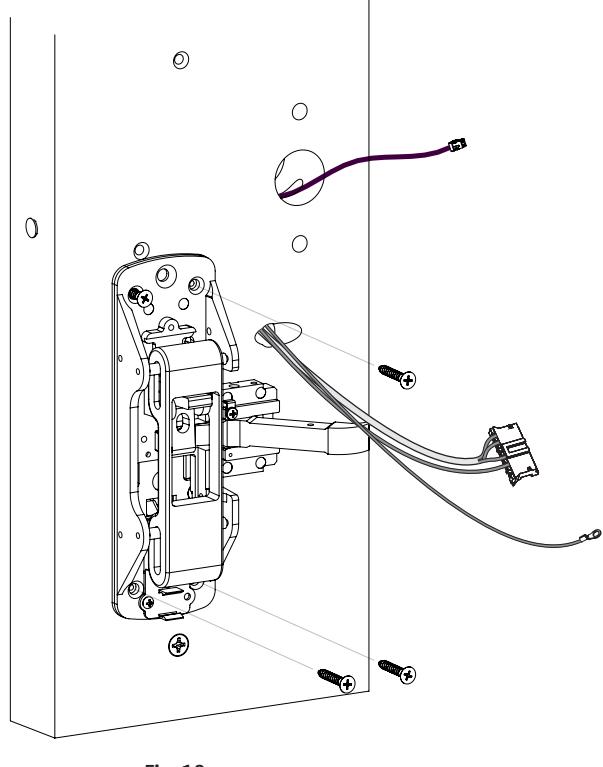
Fig. 10
7. Install rail assembly. (Fig. 11)
- a. Retrieve harness from end of rail. Harness has limited travel and can be damaged.
- b. Attach harness to female connector on chassis.
- c. Install rail and tighten chassis screws. Attach end bracket per exit device instructions.

Important Note: IN100 CVR Exit Installation Continues With Section 8

1. Prepare door
a. Verify hand and bevel of door. (Fig. 1)
NOTE: Stand on outside of locked door when determining door hand.
- b. Verify exit device is correct hand for door.
- c. Door should be fitted and hung.
- d. Verify product label.
-
e. Mark and drill door. (Fig. 2)
- If mullion is used, install prior to installing hardware
- Doors should be pre-prepped (recommended)
Prior to installation, all holes must be free of burrs, debris and sharp edges.
Prepare door according to appropriate template (see website).
- Field Template (ships with product): MEFT25
- Door Manufacturer's Template (online): MEDT69
- Exit Device Installation Instructions: FM583
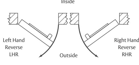

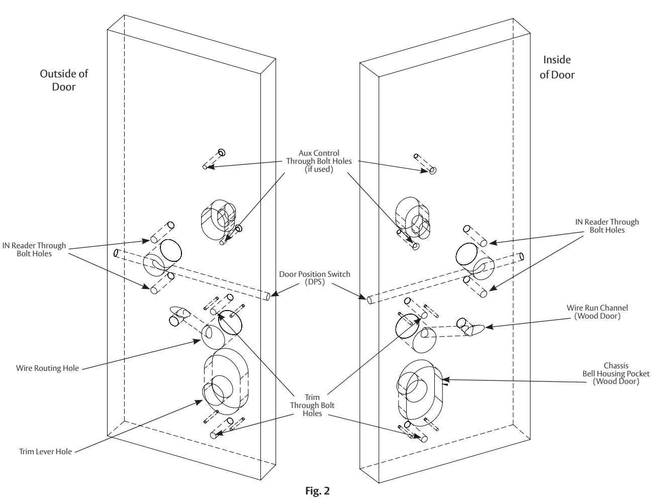

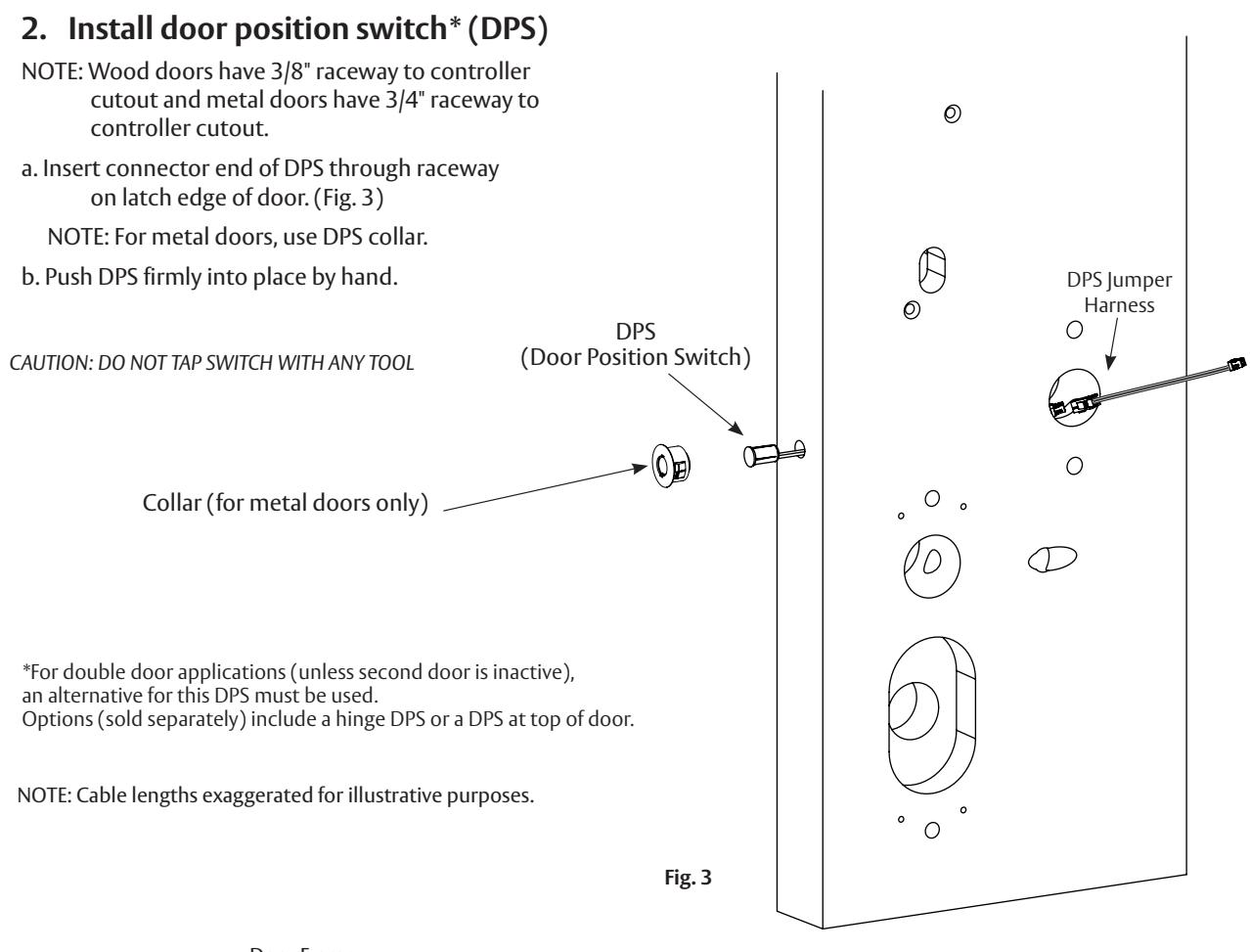
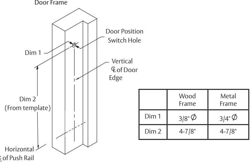
Fig. 4

3. Mount exit device chassis
NOTE : Exit chassis harness consists of a 6-pin female connector and (2) ground wire terminals. (Fig. 5, 6)
- a. Feed 6-pin connector and larger ground lug straight through to outside of door. (Fig. 5, 6)
- b. For exterior application, use trim gasket to seal between trim escutcheon and outside door surface (Fig. 5).
4. Mount exit trim. (Fig. 6)
NOTE: For exterior applications, use trim gasket as seal between trim escutcheon and outside door surface.
a. Connect motor harness adapter to chassis harness connector.
NOTE : For MELR install, skip next step (b.)
b. For wood doors: Route trim wire harness connector through cylinder hole, then up and through wire run channel to controller cutout.
For metal doors: Route trim wire harness through cylinder hole and out controller cutout.
- c. Pass top trim mounting post through chassis harness ground lug.
- d. Ensure trim spindle engages lower hub of exit chassis.
- e. Partially tighten two (2) chassis through bolts.
Do not fully tighten chassis screws until after rail installation Step 5)
5. Install rail assembly (Fig. 8)
- a. Retrieve harness from end of rail. Harness has limited travel and can be damaged.
- b. Attach harness to female connector on chassis.
- c. Install rail and tighten chassis and trim screws.
- d. Attach end bracket per exit device instructions.
e. Install top and bottom cases and pin vertical rods to chassis per exit device instructions. f. Attach covers.
Important Note: IN100 SVR Exit Installation Continues With Section 8

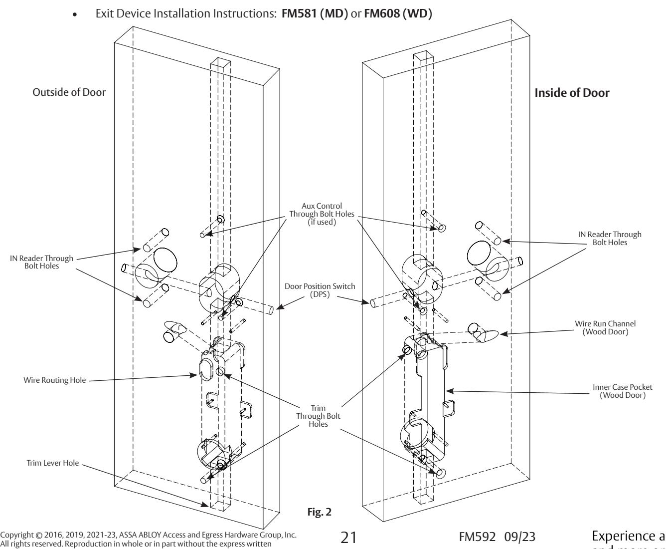
8 IN100 Installation
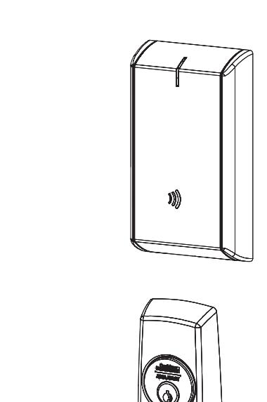
1. Install outside reader
- a. Orient reader so LED lens is at top. (Fig. 1)
- b. Feed cable/connector through door from outside to inside.
- c. Install reader to outside of door by aligning mounting posts with door preparation holes. Hold reader flush against door while ensuring proper alignment.
- d. Feed reader harness and DPS connectors through inside mounting assembly and gasket if required*. (Fig. 2)
- e. Secure mounting assembly while ensuring proper alignment of outside reader and tighten two (2) throughbolts on inside of door to secure reader. (Fig. 2)
- f. Secure ground lug with #6-32 machine screw. (Fig. 3) *NOTE:
- Gasket is required for outdoor installations
- Do not use gasket for fire-rated openings
- If installing with gasket, separate gasket from mounting plate to feed cables/connectors through holes as indicated (Fig. 2)
- Once cables/connectors are fed through, reattach gasket to mounting plate
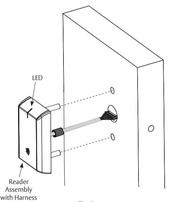
Fig. 1
8 IN100 Installation (Continued)
g. Secure the following connectors to their respective terminals (Fig. 4):
CAUTION: Do not touch or allow debris to enter connector contacts.
- Secure 4-pin DPS connector
- Secure 10-pin lock body assembly connector
NOTE: For UL294 applications, the power supply shall be UL294 Listed, Class 2
NOTE: For ULC-60839-11-1 applications, the power supply shall be ULC-60839-11-1 (Security Grade Level 2 or better) Listed Class 2, or ULC-S319 (Security Grade Level 2 or better) Listed Class 2, or ULC-S318 Listed, Class 2
NOTE: For ULC-60839-11-1 applications the power supply wiring shall be a maximum length of 3 meters (9.8 feet)
IMPORTANT: Do not run wires through bottom hole in plate this will damage wires and controller connector. Route wires around flange. (Fig. 4, Fig. 6).
- h. When all connections have been made, tuck excess cable into wire hole on inside of door.
- i. Secure mounting assembly while ensuring proper alignment of outside reader and tighten two (2) through-bolts on inside of door to secure reader. (Fig. 5)
- j. Secure 24-pin card reader connector. (Fig. 6)
| *Optional 12-24VDC Power | ||
|---|---|---|
| Remote Power Harness Wire Terminations | ||
|
2-pin
Connector |
Black | PS (-) Return |
| Red | PS (+) 12-24VDC | |
| Ring Terminal | Green | Earth Ground |
Power Supply (PS) Required - UL Class 2 Filtered & Regulated, 12-24VDC, 1.0A
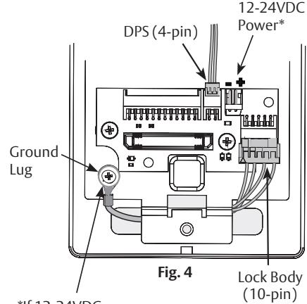
*If 12-24VDC power harness used, secure its ground (ring terminal) here as well
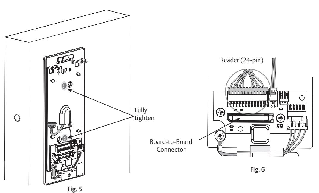

8 IN100 Installation (Continued)
2. Install inside component assembly (controller).
- a. Insert bottom tab of controller, making sure path is clear, into slot on mounting plate. (Fig. 7)
- b. Ensure proper alignment of board-to-board connectors while pivoting controller toward door until two tabs on top snap securely into place on mounting plate (Fig. 8).
CAUTION: To avoid possible damage to board-to-board connectors, care should be taken when securing controller to mounting plate. If there is resistance when securing, detach controller to determine cause before re-attaching controller.
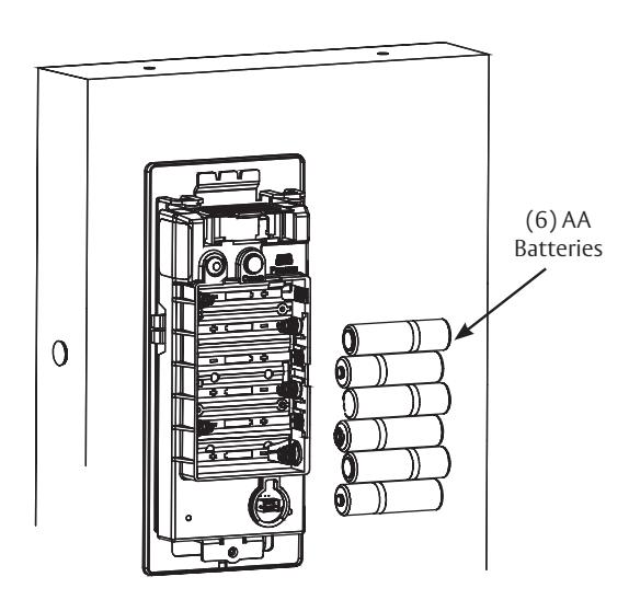
3. Install batteries.
- a. Place six (6) "AA" alkaline batteries in compartment, being careful to align polarity properly. (Figure 9)
- b. After batteries are installed, there is a slight delay; then red and green flash*, audible "beep" and lock motor will cycle.

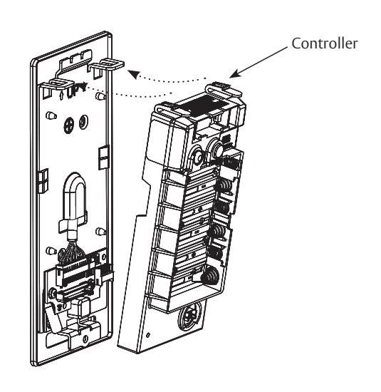
Fig. 7
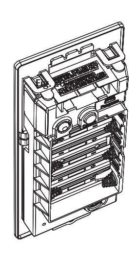
Fig. 8 Fig. 9

8 IN100 Installation (Continued)
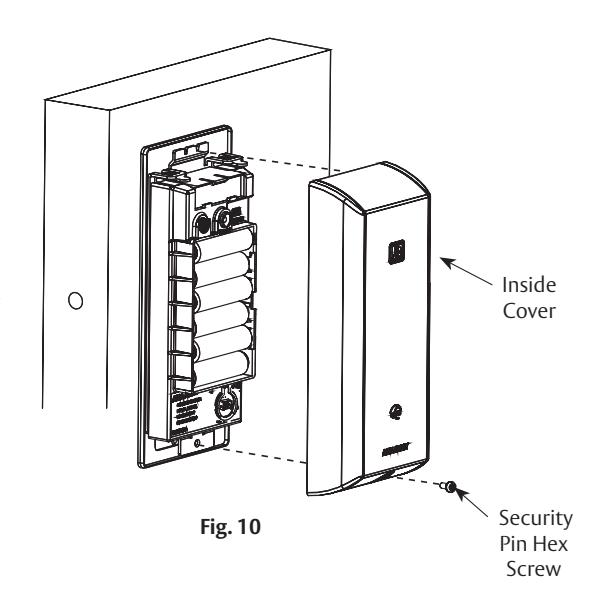
4. Install inside cover (Fig. 10)
- a. Assemble cover by hooking top edge on inside mounting plate.
- b. Carefully press bottom of cover toward door without pinching or damaging wires.
- c. Secure cover utilizing 1/8" security hex key.
NOTE: Use of power tools on this step is strongly discouraged. Over-torquing security pin hex screw will result in battery cover damage.
9 Operational Check
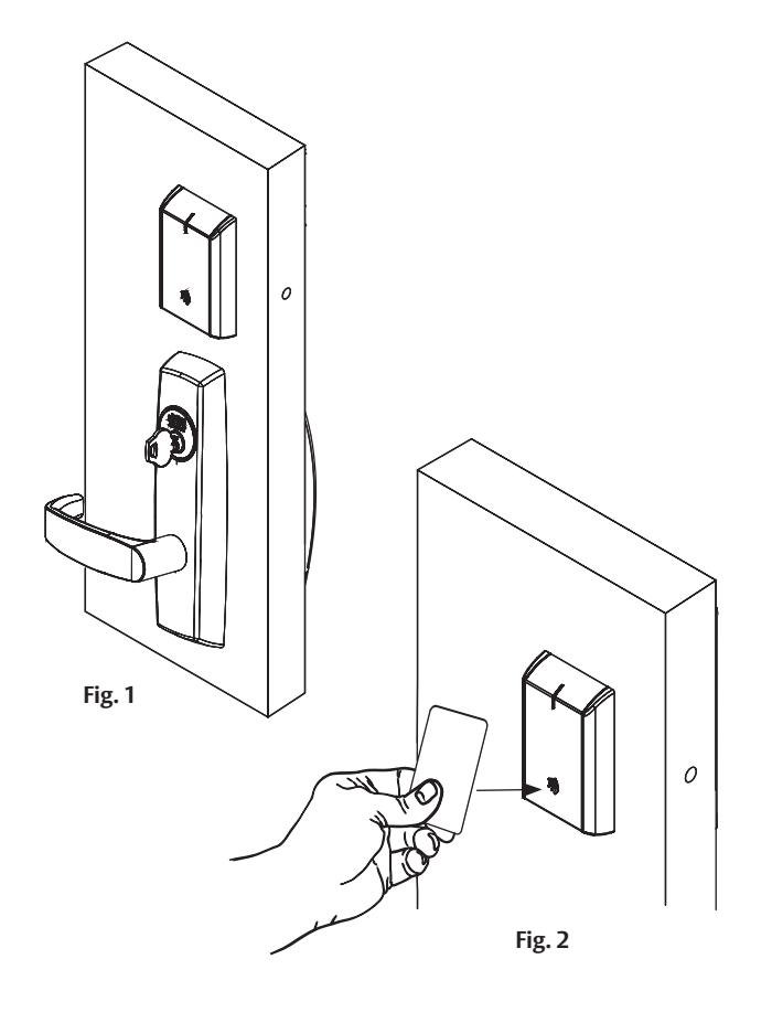
When lock is fully installed, perform following steps:
-
1. Insert key into cylinder and rotate. (Fig. 1)
- NOTE: There should be no friction against lock case, wire harness or any other obstructions.
- 2. Check that key retracts latch.
- NOTE: Key should rotate freely.
- 3. Depress exit rail; ensure it retracts latch.
- 4. Present a valid credential* to unlock outside lever; turn lever handle to ensure latch retracts. (Fig. 2)
- NOTE: Credential should approach inscription on reader as indicated to ensure credential is read properly. Do not wave credential.
- *Depending upon availability of access control system either a (denied) red flash or a green and lock motor cycle (access granted).

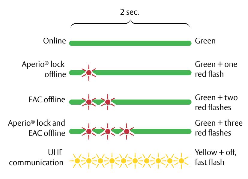
10 Communication Hub LED Indications
Communication hub has a single LED. It supports an optical scheme of red, green and yellow. Indication scheme is described by figures below:
Communication Hub NORMAL OPERATION LED indication
Some special LED indication schemes are used during lock maintenance actions:
Communication Hub MAINTENANCE LED indication

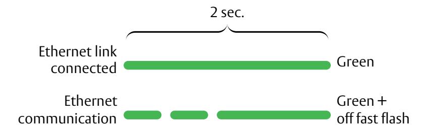
LED on AH40 communication hub indicates both status of Ethernet link level and ethernet communication:
AH40 Communication Hub ETHERNET LED indication
*For more information, refer to Aperio® Online Quick Installation Guide Document No: ST-001322

11 Lock LED Indications
Lock has three (3) LEDs. They support an optical scheme with red, yellow and green. Indication scheme described by figures below:
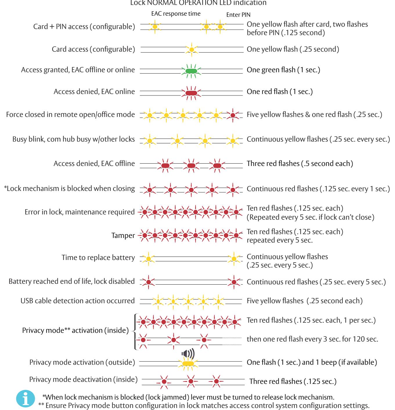
Some special LED indication schemes are used during lock maintenance actions:
Lock MAINTENANCE OPERATION LED indication
Enter configuration mode Five yellow flashes (.125 sec. each)

12 Lock Self-Test LED Indications
After replacing batteries, a Power on Self Test (POST) is performed. The result is indicated using a series of red and green LED flashes as described by figures below:
Battery Not Fully Charged
Error in lock is an indication -10 quick (125ms) red blinks, that either new batteries are not at right voltage or a backward battery has been installed; battery not fully charged; energy counter not reset or no Power on self-test performed.

Test Pass
1 red (1s) + 1 green (1s), Power on self-test passed. See table below.
POST Successful One red, one green flash (1 second)
Test Fail
1 red (1s) + 3 blinks (500ms, green or red), at least one test failed (red). See table below.
If a fatal error is detected, lock will enter an Error state and continuously indicate fatal error. Lock will not read cards or unlock.
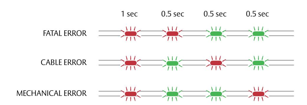
| FATAL ERROR |
Tests core functionality. MCUs, memory and internal
communication, etc. |
|---|---|
| CABLE ERROR |
Tests communication between different
parts in system, i.e. different boards connected with a wire. |
| MECHANICAL ERROR | Test related to moving parts of lock. |

13 Lock Busy LED Indications
Lock BUSY indicates lock is processing a card (such as a key configuration card for online SE processor or offline void list card with many entries). Card should be kept in close proximity to reader until end of process. Lock BUSY indication does not cancel or overwrite any other indications. Indications related to access permissions or setup card processing are still present.
Indication scheme is described by figures below:
Lock BUSY indication

Lock BUSY indication Mixed with Scenario for Offline Audit Trail Card
Online BLE Access
Online SE Keys Setup Card (Configuration)

*Introduced with firmware version 3.8 - in prior firmware versions only "Config card processed" LED indication is displayed.


IN100 Series PED5000 Series Exit Devices

39

Corbin Russwin 225 Episcopal Road Berlin, CT 06037 Phone: 800-543-3658 Fax: 800-447-6714
corbinrusswin.com
Copyright © 2020-2023 ASSA ABLOY Access and Egress Hardware Group, Inc. All rights reserved. Reproduction in whole or in part without the express written permission of ASSA ABLOY Access and Egress Hardware Group, Inc. is prohibited. Patent pending and/or patent - www.assaabloydss.com/patents.
HID, iCLASS, and Edge are trademarks or registered trademarks of HID Global Corporation.