Corbin Russwin IN100 Series with ML2000 Series Mortise Locks Installation Instructions_FM403
Open the original PDF document
View PDFMortise Lockset IN100 with Aperio™ Technology Installation Instructions

Attention Installer
Please read these instructions carefully to prevent missing important steps.
Misalignment can cause premature wear and a lessening of security.
Please Note: Improper installations may result in damage to the lock and void the factory warranty. Important: The accuracy of the door preparation is critical for proper functioning and security of this lock.
WARNING
This product can expose you to lead which is known to the state of California to cause cancer and birth defects or other reproductive harm. For more information go to www.P65warnings.ca.gov.
08/2018
For Technical Assistance call Corbin Russwin at 1-800-810-WIRE (9473)

Table of Contents
| 1) Warning | 2 |
|---|---|
| 2) General Description | 3 |
| 3) Specifications / Features | 3 |
| 4) Product Illustrations | 4 |
| 5) Installation Instructions | 6 |
| 6) Operational Check | 20 |
| 7) LED Indications | 21 |
1) Warning
Warning: Changes or modifications to this unit not expressly approved by the party responsible for compliance could void the user's authority to operate the equipment.
This device complies with Part 15 of the FCC Rules. Operation is subject to the following two conditions: (1) this device may not cause harmful interference, and (2) this device must accept any interference received, including interference that may cause undesired operation.
Note: This equipment has been tested and found to comply with the limits for a Class B digital device, pursuant to Part 15 of the FCC Rules. These limits are designed to provide reasonable protection against harmful interference in a residential installation.
This equipment generates, uses and can radiate radio frequency energy and if not installed and used in accordance with the instructions, may cause harmful interference to radio communications. However, there is no guarantee that the interference will not occur in a particular installation. If this equipment does cause harmful interference to radio or television reception, which can be determined by turning the equipment off and on, the user is encouraged to try to correct the interference by one or more of the following measures:
- Reorient or relocate the receiving antenna
- Increase the separation between the equipment and receiver
- · Connect the equipment into an outlet on a circuit different from that to which the receiver is connected
- Consult the dealer or an experienced technician for help
The term "IC:" before the radio certification number only signifies that Industry Canada technical specifications were met. This Class B digital apparatus meets all requirements of the Canadian Interference Causing Equipment Regulations. Operation is subject to the following two conditions: (1) this device may not cause harmful interference, and (2) this device must accept any interference received, including interference that may cause undesired operation.
Cet appareillage numérique de la classe B répond à toutes les exigences de l'interférence canadienne causant des règlements d'équipement. L'opération est sujette aux deux conditions suivantes: (1) ce dispositif peut ne pas causer l'interférence nocive, et (2) ce dispositif doit accepter n'importe quelle interférence reçue, y compris l'interférence qui peut causer l'opération peu désirée.

To comply with "Fire Listed" doors, the batteries must be replaced with alkaline batteries only.
To avoid possible damage from electrostatic discharge (ESD), some basic precautions should be used when handling electronic components:
- Minimize build-up of static by touching and/or maintaining contact with unpainted metal surfaces such as door hinges, latches, and mounting plates especially when mounting electronic components such as readers and controllers onto the door.
- Leave components (reader and controller) protected in their respective anti-static bags until ready for installation
- Do not touch pins, leads or solder connections on the circuit boards
IN100 Mortise Lock

2) General Description
The Corbin Russwin® IN100 mortise lock with Aperio™ Technology makes it easy and cost-effective to bring access control to more doors. It uses local wireless communication between the lock and an Aperio hub to connect to an access control system, eliminating the greatest cost and inconvenience of traditional access control – the wiring at the door. The IN100 utilizes HID® multiCLASS SE® technology; it supports heightened identity security and multiple credentials, including mobile access.
All technology features are supported by the physical security of Corbin Russwin ANSI/BHMA Grade 1 hardware quality components that provide high security, performance and durability.
3) Specifications / Features
Hardware Specifications
- Latch Stainless Steel (Easily field reversible without disassembling lock body)
- Deadbolt Stainless Steel
- Auxiliary Latch Stainless steel, non-handed
- Door Thickness 1-3/4" Standard; can be furnished for other door thicknesses upon request. Consult factory.
- Case 12 gauge heavy duty wrought steel
- Outside lever controlled by reader or key retracts latch
- Inside Lever produces REX (request to exit) signal and retracts latch and deadbolt*
- UL fire listed
- May be used for both indoor and exterior applications
- A weather-protective gasket is required for exterior applications
Electronic Specifications
- Input Power: DC 9V, 1.5A (6 AA alkaline batteries)
- Optional hard-power 12VDC to 24VDC
-
HID® multiCLASS SE® technology offers support for the following credentials:
-
High Frequency (13.56 MHz):
- HID iCLASS®
- HID iCLASS SE® (SIO-enabled)
- HID iCLASS® Seos™
- HID MIFARE® SE
- HID DESfire® EV1 SE
- MIFARE Classic
- DESfire EV1
-
Low Frequency (125 kHz):
- HID Prox®, AWID,EM4102
- NFC-enabled Mobile Phones
-
High Frequency (13.56 MHz):
- Utilizes IEEE 802.15.4 wireless communication
- Multiple time zone and holiday access scheduling
- First-in unlock or automatic unlock configuration, based on specified time schedule
- Uses AES 128-bit wireless encryption**
- Privacy button
** For specific security information, please contact your local ASSA ABLOY Door Security Solutions sales consultant or call 800-810-WIRE.

4) Product Illustrations

| ITEM | PART NUMBER/ORDER STRING | DESCRIPTION | COLOR/TRIM | QTY |
|---|---|---|---|---|
| 1 | IN-100-EM01[locktype]*-IP-B |
HID iCLASS®, HID iCLASS SE® (SIO-enabled), HID iCLASS® Seos™, HID MIFARE®
SE, HID DESfire® EV1 SE, HID Prox®, NFC-enabled mobile phones |
Black | 1 |
| IN-100-EM01[locktype]*-IP-W |
HID iCLASS®, HID iCLASS SE® (SIO-enabled), HID iCLASS® Seos™, HID MIFARE®
SE, HID DESfire® EV1 SE, HID Prox®, NFC-enabled mobile phones |
White | 1 | |
| IN-100-EM01[locktype]*-IP-MB-[finish]** |
HID iCLASS®, HID iCLASS SE® (SIO-enabled), HID iCLASS® Seos™, HID MIFARE®
SE, HID DESfire® EV1 SE, HID Prox®, NFC-enabled mobile phones |
Black with metal trim | 1 | |
| IN-100-EM01[locktype]*-IP-MW-[finish]** |
HID iCLASS®, HID iCLASS SE® (SIO-enabled), HID iCLASS® Seos™, HID MIFARE®
SE, HID DESfire® EV1 SE, HID Prox®, NFC-enabled mobile phones |
White with metal trim | 1 | |
| IN-100-EM01[locktype]*-IPS-B | All credentials supported by the IP option plus MIFARE Classic and DESfire EV1 | Black | 1 | |
| IN-100-EM01[locktype]*-IPS-W | All credentials supported by the IP option plus MIFARE Classic and DESfire EV1 | White | 1 | |
| IN-100-EM01[locktype]-IPS-MB-[finish]** | All credentials supported by the IP option plus MIFARE Classic and DESfire EV1 | Black with metal trim | 1 | |
| IN-100-EM01[locktype]-IPS-MW-[finish]** | All credentials supported by the IP option plus MIFARE Classic and DESfire EV1 | White with metal trim | 1 | |
| 2 | 820F558 | Inside Mounting Kit (mounting plate & hardware) | 1 | |
| 3 | N/A | AA battery | 6 | |
| 4 | 820F489 | Inside Escutcheon | Black | 1 |
| 820F499 | Inside Escutcheon | White | ||
| 820F525 [finish]** | Inside Escutcheon | Black with metal trim | ||
| 820F535 [finish]** | Inside Escutcheon | White with metal trim | ||
| 5 | FM355 | Field prep template (not shown) | 1 | |
| 6 | T31202 | Door manufacturers template (not shown) | 1 | |
| FM403 | Instructions (this manual) | 1 |
* ML20133/36 (example: IN-100-EM01ML20136-IP-B)
** Specify finish

4) Product Illustrations (Continued)
Tools Required:
- Phillips Screw Driver #2, #3
- Flat Blade Screw Driver (Standard size)
- 1/8" Security Allen Wrench (supplied
- 7/64" Allen Wrench (supplied)
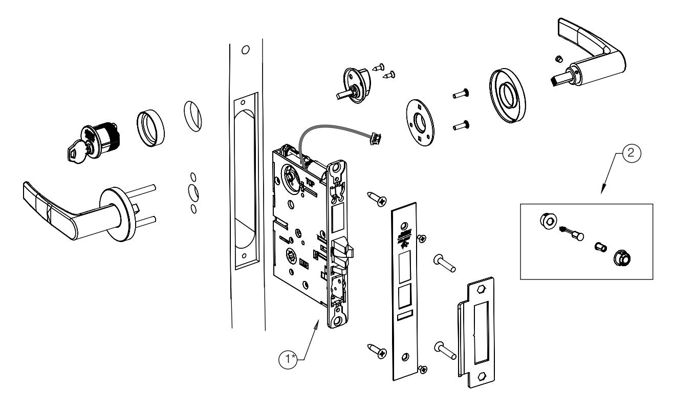
| 1 | 784F848[handing]*26D | ML20133/ML20134 Lock Case (No Deadbolt)** | 1 |
|---|---|---|---|
| 784F858[handing]*26D | ML20135/ML20136 Lock Case (With Deadbolt)** | ||
| 2 | 820F609 | Door Position Switch Kit (SPDT) | 1 |
* Replace with handing (L, LR, R, RR)
For parts not listed, refer to ML2000 Parts and Service Manual
** Escape Return functionality is not available with the IN100 ML201xx mortise lock.

5) Installation Instructions
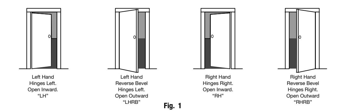
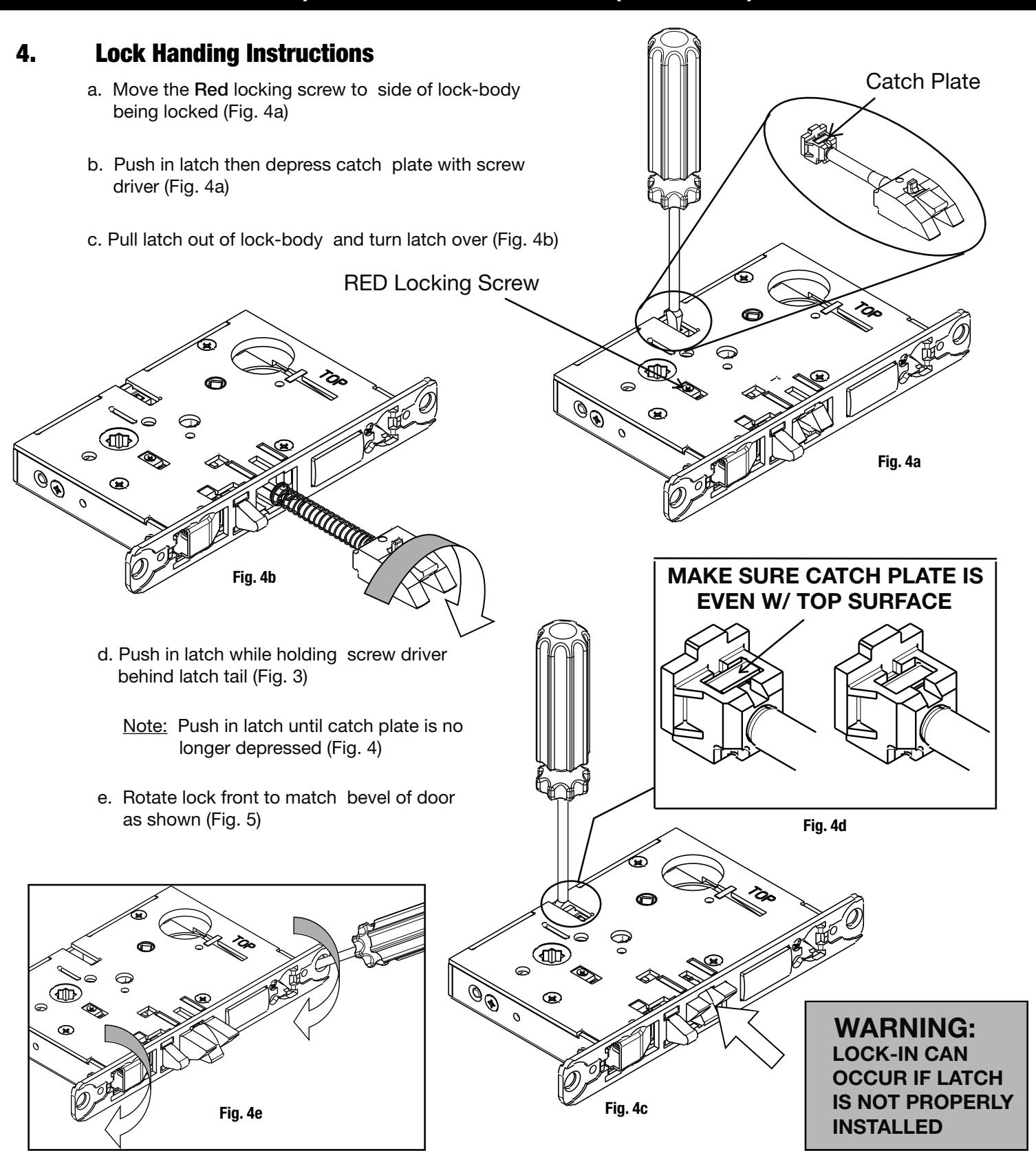
1. Verify Hand and Bevel of door
Illustrations shown are as viewed from the outside or secure side of opening.
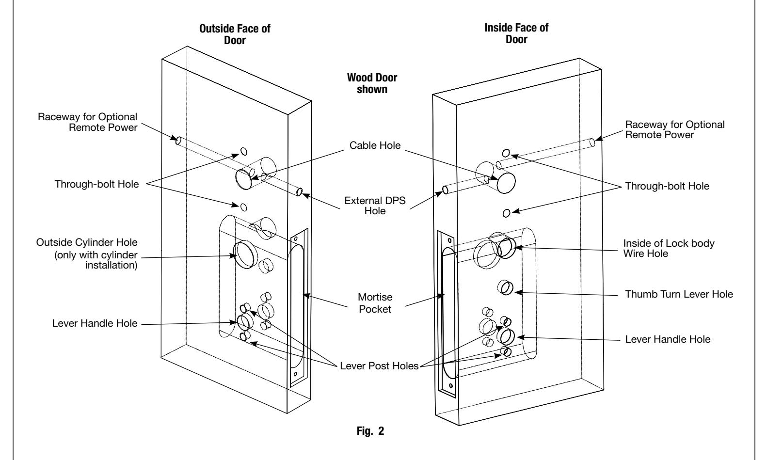
2. Door Preparation
Prep door according to supplied door marker (FM355). For door manufacturer templates visit www.corbinrusswin.com and reference template # T31202.

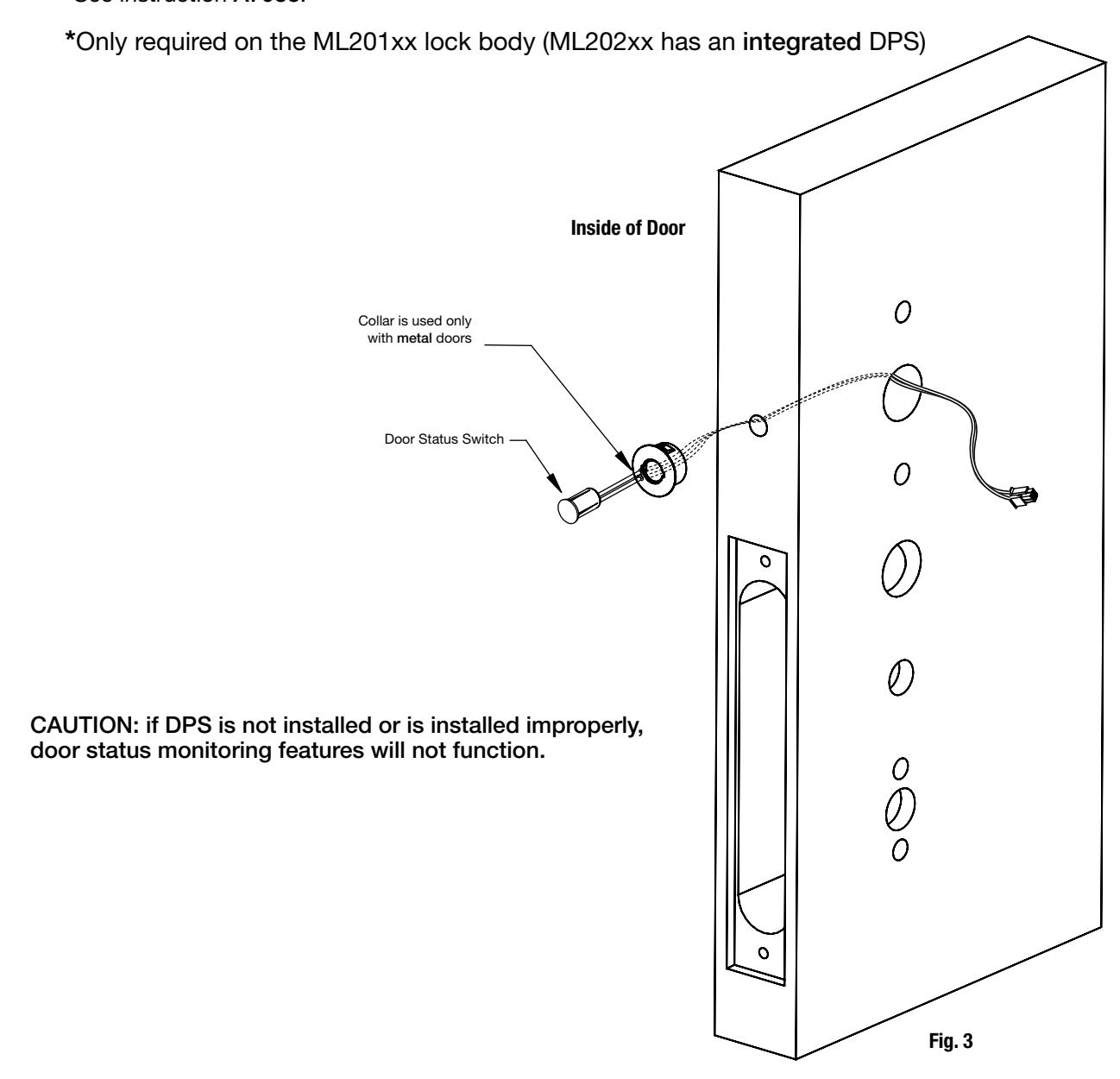
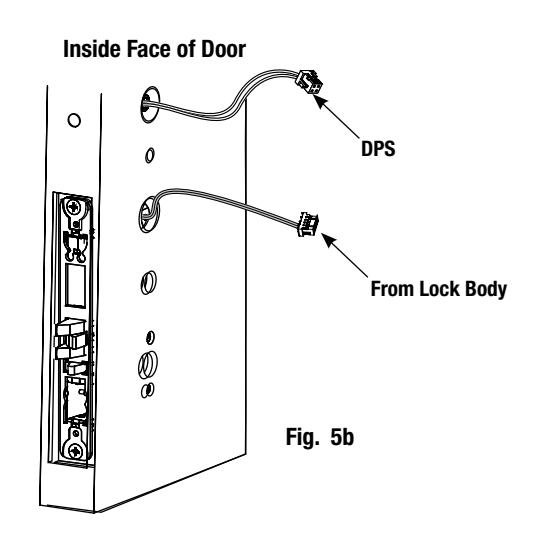
3. Install Door Position Switch (DPS)
-
Illustrations shown are as viewed from the outside or secure side of opening. a. Push wires through raceway toward lock prep.
- b. Push DPS firmly into place by hand. Note: DO NOT TAP SWITCH WITH ANY TOOL.
- c. Install magnet into door frame. Push firmly into place by hand. See instruction A7983.


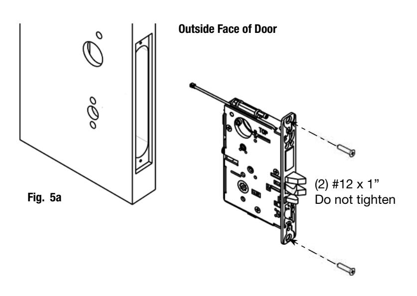
5. Install Lock Body in Door:
- a. Feed wires through 1-5/16" diameter hole on INSIDE of door while installing lock body (Fig. 5a).
- b. Pull wires through hole while inserting lock body. DO NOT push wires back into cylinder hole (Fig. 5b). Important: Door must remain open during installation. Use door stop.
- c. Install, but do not tighten two #12 x 1" combination screws through lock body (Fig. 5a).
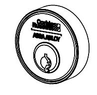
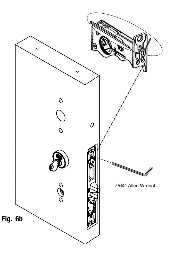
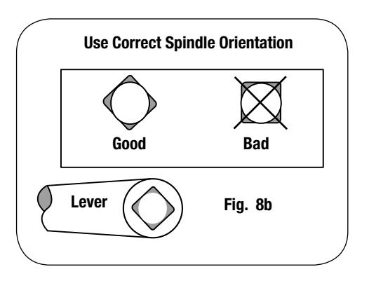
6. Install Cylinder:
-
a. Slide cylinder through collar. Thread cylinder into lock body (Fig. 6a).
- Note: Make sure cylinder is oriented correctly (Fig. 6a1).
- b. Tighten cylinder clamp using 7/64" allen wrench (Fig. 6b).
- c. Turn the key to make sure that lock functions correctly (latch, deadbolt, and key).
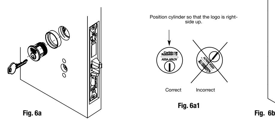
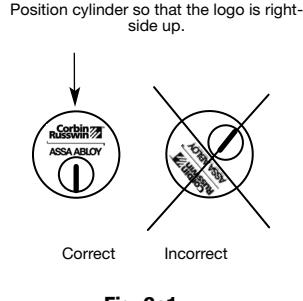
Fig. 6a1

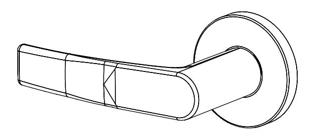
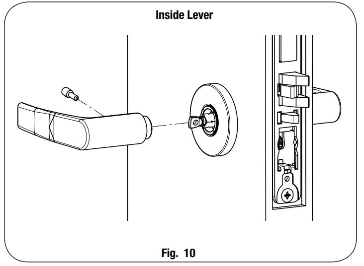
7A. Install Standard Lever Trim:
(Refer to Step 7b on following pages for Museo® Trim):
IN100 Mortise Lock

5) Installation Instructions (Continued)
Step 4
Step 5 Align adjustment bolt with threaded hole in lever
Adjustment bolt needs to be threaded in farther.
Adjustment bolt needs to be unthreaded.
Adjustment bolt fully aligned.
Step 6 Install I/S lever with set screw:
Notes:
- Unthread adjustment bolt approximately four turns for a good starting point (after being fully tightened).
- Make sure O/S lever is fully inserted into adapter plate before aligning adjustment bolt.

Step 2
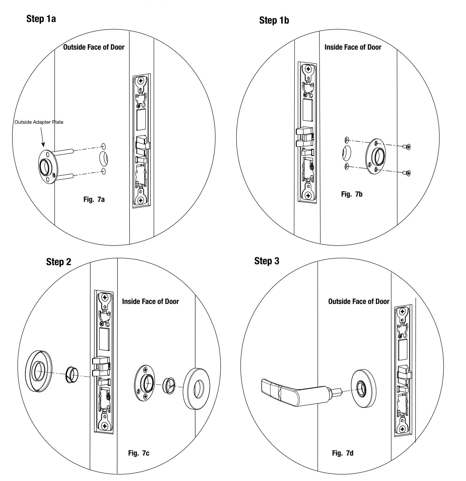
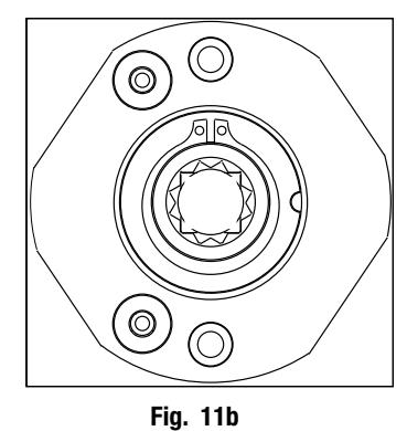
7B. Install Museo® Trim:
Step 1 Thread adapter plate hub into lever and fully tighten
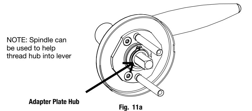
Align adapter plate hub with square hole in lever; keeping hub as tight as possible
Step 3 Install O/S trim assembly and inside adapter plate
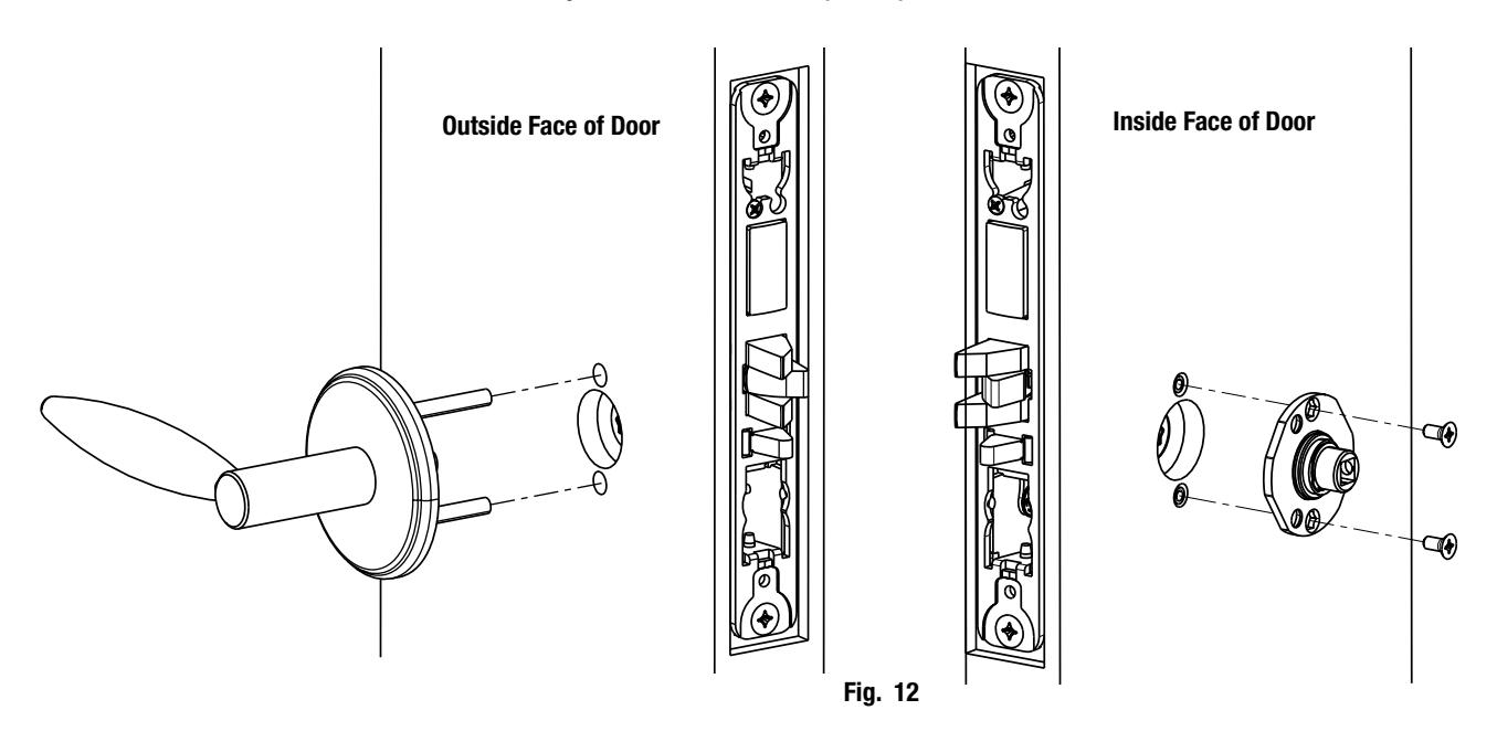

Install Spindle and Rose: Step 4
a. Align studs on rose with bushings in adapter plate.
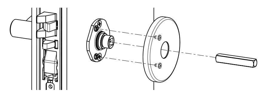
Fig. 13a
Install I/S lever with set screw: Step 5
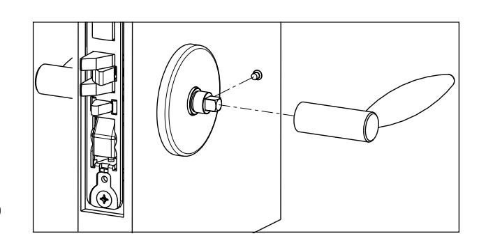
Fig. 13b
Install Armored Front: Step 6
- a. Tighten (2) screws through lock body.
- b. Attach armored front with two #8 x ¼" screws (Fig. 13c).
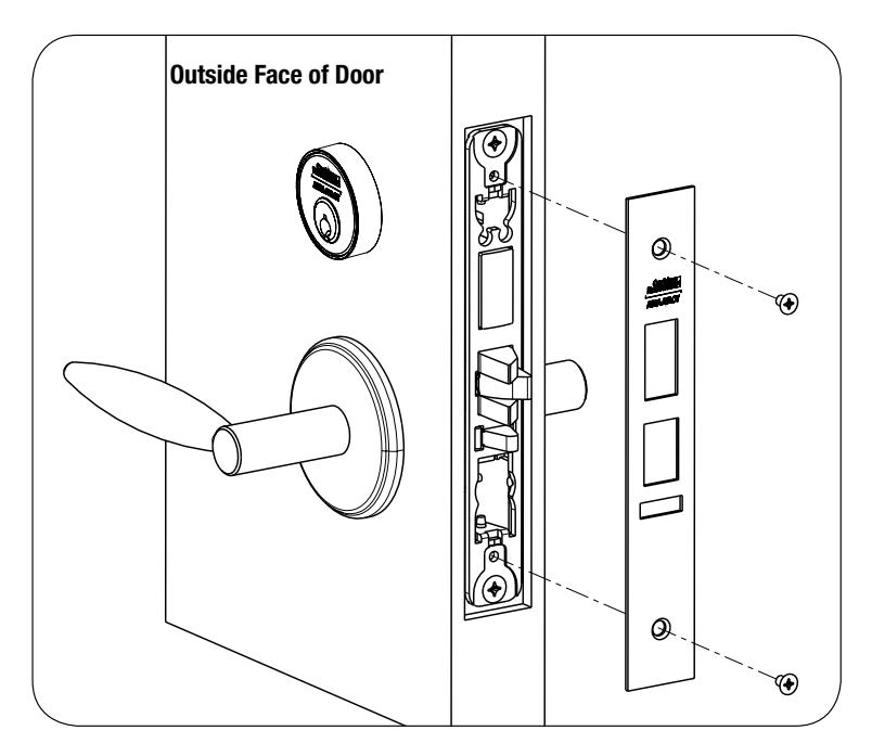
Fig. 13c

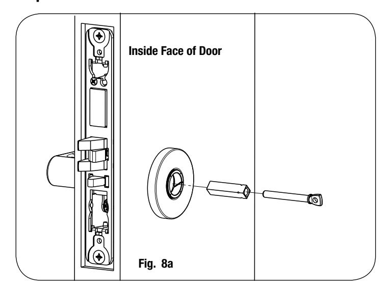
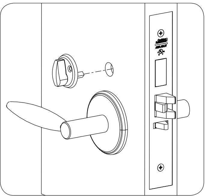
8. Install Turn Piece:
Step 1
Step 2
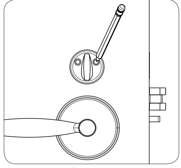
Fig. 13d Fig. 13e
Step 3
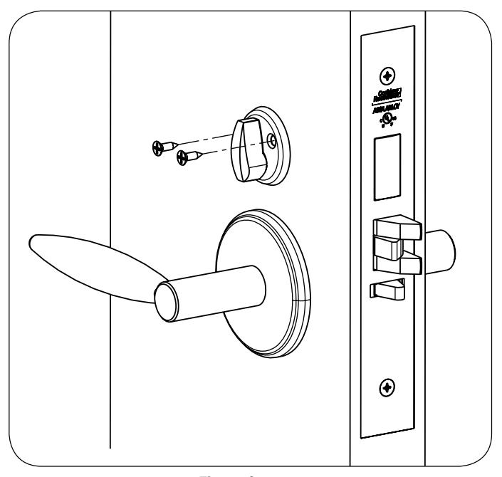
Fig. 13f

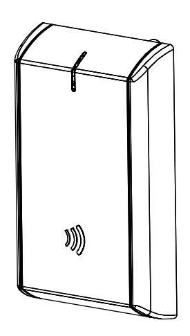
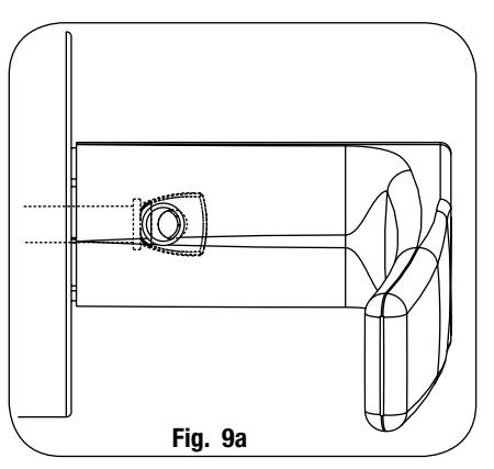
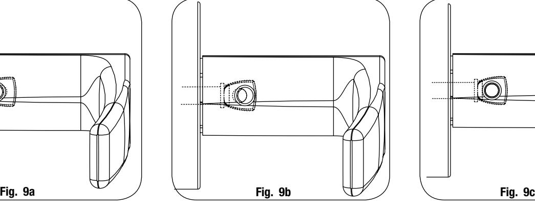
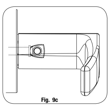
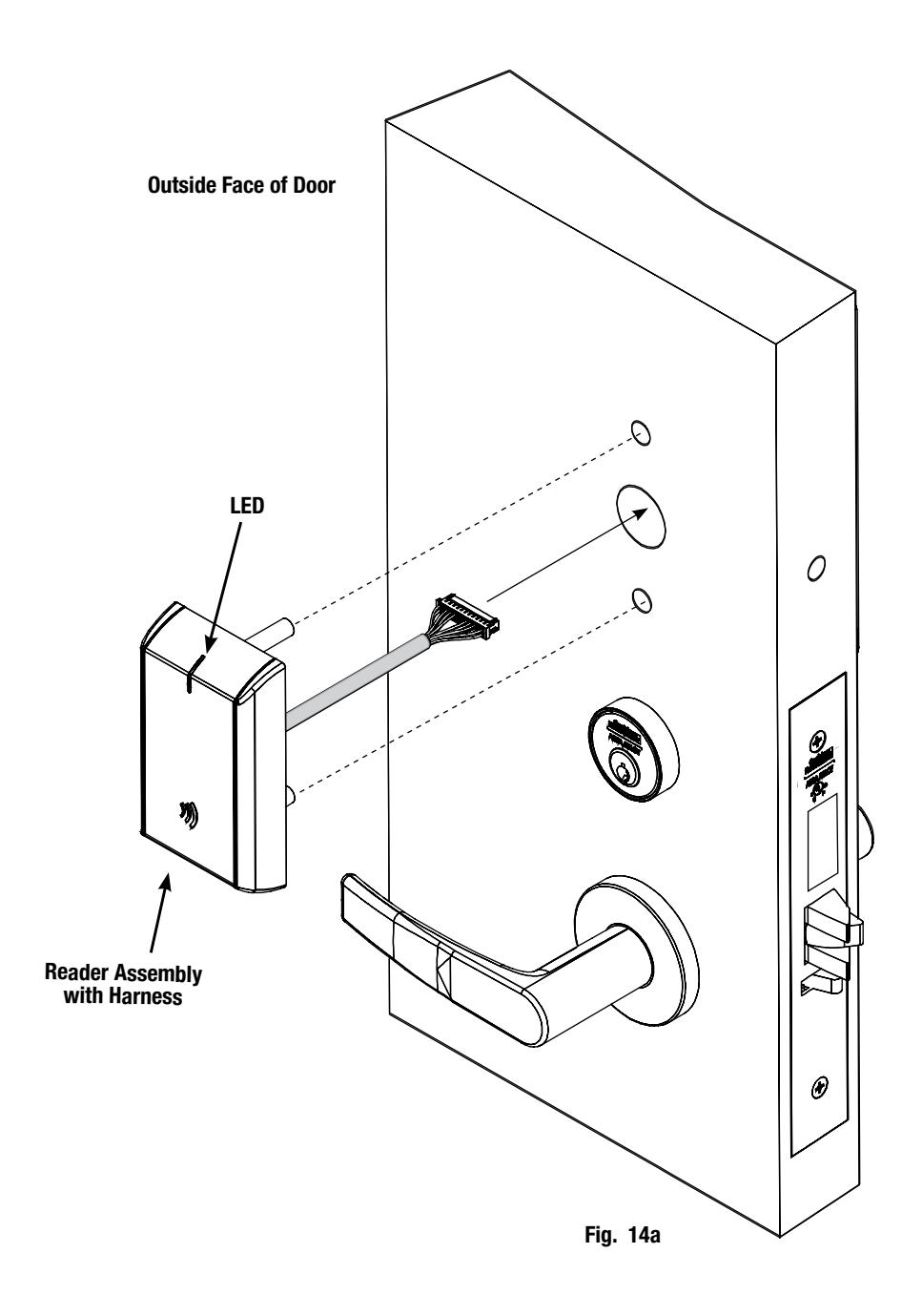
9. Install Outside Reader and Inside Mounting Plate:
- a. Orient the reader so the LED lens is at the top.
- b. Feed the reader harness through the door (from outside to inside).
- c. Install the reader to the outside of door by aligning the mounting posts with the door preparation holes. Hold the reader flush against door while ensuring proper alignment.

-
d. Feed the reader harness and DPS connectors through the inside mounting assembly (and gasket if required*). See Figure 11B.
- IMPORTANT: Do not run wires through bottom flange hole in plate (Fig. 11B, C) it will damage wires and the controller connector. Route wires around flange, do not route wires through the flange hole (Fig. 11C).
- e. Tuck excess cable into wire hole on inside of door.
- f. Begin to secure the mounting assembly by partially tightening the (2) through-bolts on the inside of the door while ensuring proper alignment as you secure the reader (Fig. 11B).
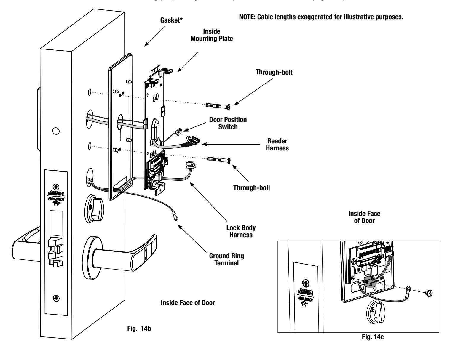
g. Secure ground lug with #6-32 machine screw (Fig.10C).
*Gasket is required for outdoor installations. Do not use gasket for fire-rated openings.
If installing with gasket; separate gasket from mounting plate to feed cables/connectors through holes as indicated (Fig. 14c).
Once cables/connectors are fed through, reattach gasket to mounting plate.

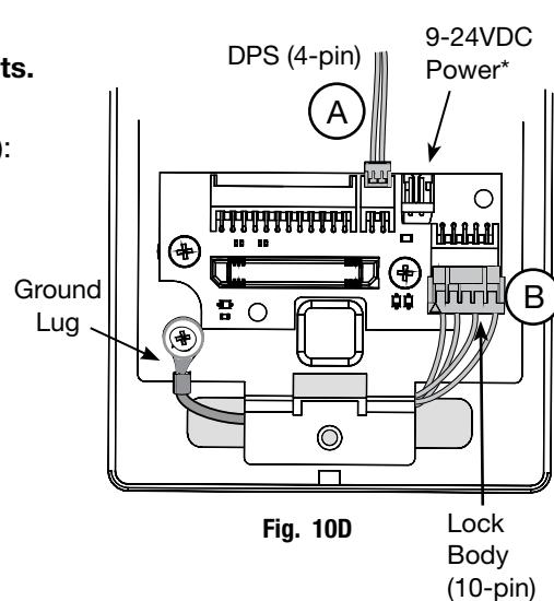
10. Installation of Connectors
CAUTION - Do not touch or allow debris to enter connector contacts.
Secure the following connectors to their respective terminals (Fig. 10D):
- A. Secure the 4-pin DPS connector.
- B. Secure the 10-pin lock body assembly connector.
*NOTE: Optional 2-pin external 9-24VDC power connector.
IMPORTANT: Do not run wires through bottom hole in plate - it will damage wires and the controller connector. Route wires around flange, do not route wires through the flange hole (Fig. 10B, D).
C. When all connections have been made, tuck excess cable into wire hole on inside of door.
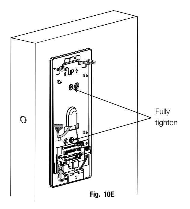
Secure Mounting Plate
-
D. Secure the mounting assembly while ensuring proper alignment of outside reader and tighten the (2) through-bolts on the inside of the door to secure the reader (Fig. 10E).
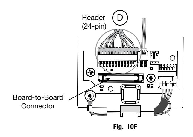
- E. Secure the 24-pin card reader connector (Fig. 10F).

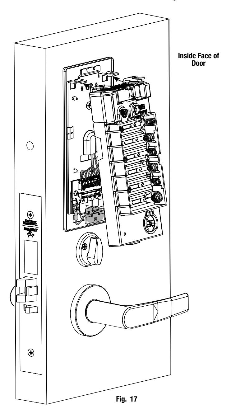
11. Installation of Inside Module Component Assembly
- a. Insert top tabs of controller into slots on mounting plate (Fig. 17).
- b. Ensure proper alignment of board-to-board connectors while pivoting bottom of controller toward door until tab on bottom snaps securely into place on mounting plate.
CAUTION: To avoid possible damage to board-to-board connectors, care should be taken when securing controller to mounting plate. If there is resistance when securing, detach controller to determine cause before re-attaching controller.

12. Installing Batteries
- a. Place (6) "AA" alkaline batteries in the compartment, being careful to align polarity properly (Fig. 18).
- b. After batteries are installed, there is a slight delay; then red and green flash, audible "beep" and lock motor will cycle.
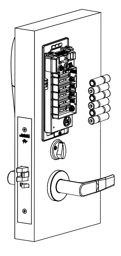
Fig. 18
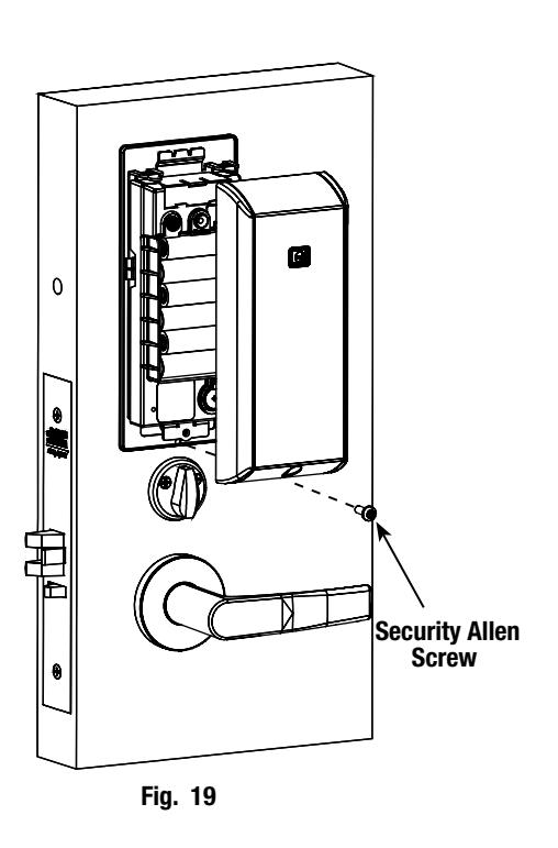
13. Inside Cover Installation
- a. Assemble cover by hooking top edge on inside mounting plate.
- b. Carefully press bottom of cover toward door with out pinching or damaging any wires.
- c. Fully secure cover by tightening the security screw at bottom of cover (Fig.19), utilizing a security allen wrench.

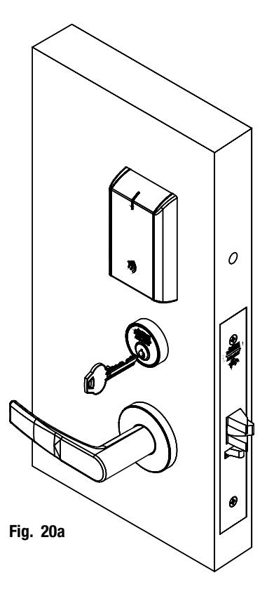
6) Operational Check
When lock is fully installed, perform the following steps:
- a. Insert key into cylinder and rotate (Fig. 20a).
- b. There should be no friction against lock case, wire harness or any other obstructions.
- c. Check that the key retracts the latch.
- d. The key should rotate freely.
- e. Try the inside lever; ensure it retracts latch.
- f. Present a valid credential* (Fig. 20b) to unlock outside lever; turn lever handle to ensure latch retracts.
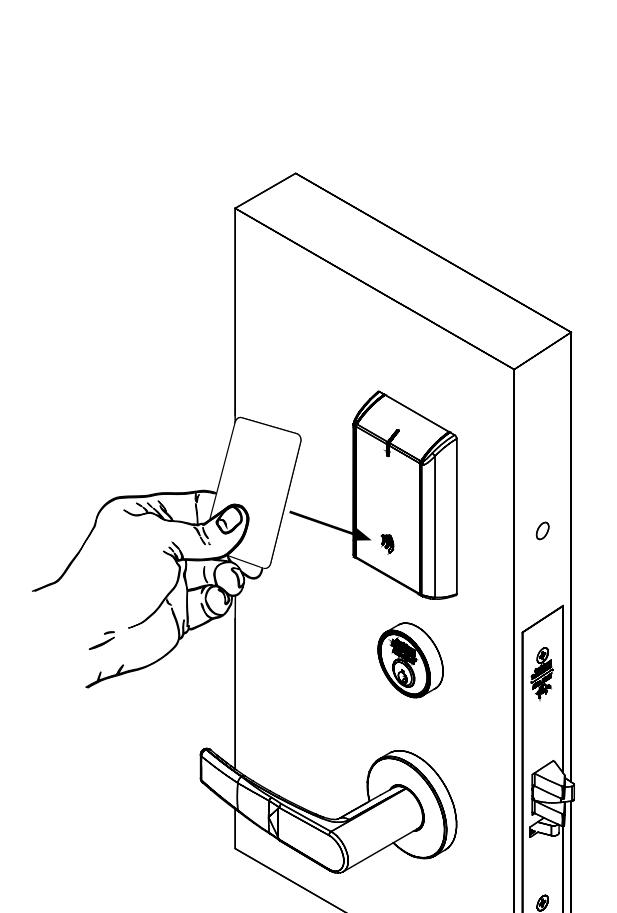
Note: The credential should approach the inscription on the reader as indicated (Fig. 20b) to ensure that the credential is read properly.
Do not wave credential.
Fig. 20b

7) LED Indications
The communication hub has a single LED. It supports an optical scheme of red, green and yellow. The indication scheme is described by the figures below:
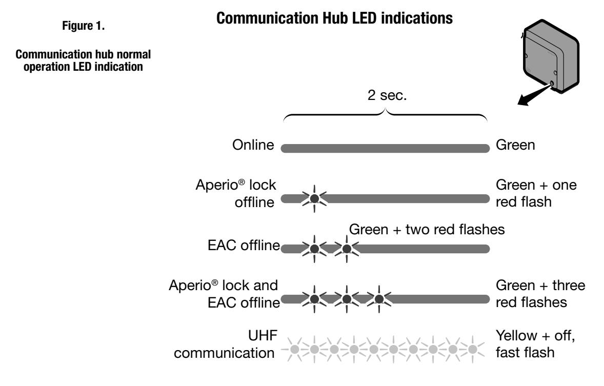
Some special LED indication schemes* are used during lock maintenance actions:

Ethernet LED indication
The LED on the AH40 communication hub* indicates both the status of the Ethernet link level and ethernet communication:
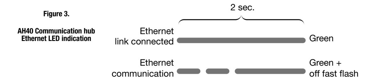
*For more information, refer to Aperio Online Quick Installation Guide (Document No: ST-001322-PF Date: 2015-12-23)
IN100 Mortise Lock

Lock LED indications
The lock has three LEDs. They support an optical scheme with red, yellow and green. The indication scheme is described by the figures below:
Figure 4. Lock normal operation LED indication
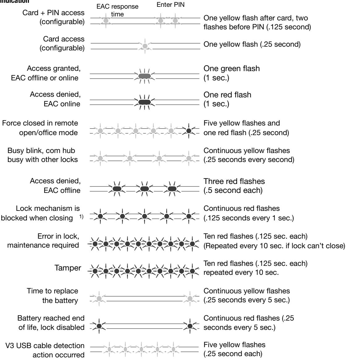

1) When the lock mechanism is blocked (lock jammed) the lever must be turned to release the lock mechanism.
Some special LED indication schemes are used during lock maintenance actions:
Figure 5. Lock hub normal operation LED indication
Enter configuration mode Five yellow flashes (.125 second each)
IN100 Mortise Lock

Lock Self-Test LED indication
After replacing batteries, a Power on Self Test (POST) is performed. The result is indicated using a series of red and green LED flashes as described by the figures below.
LED indication after power up/replacement of the battery
8.3.1 Battery not fully charged
Error in lock is an indication -10 quick (125ms) red blinks, that either new batteries are not at the right voltage or a backward battery has been installed; battery not fully charged; energy counter not reset or no Power on self-test done.

8.3.2 Test pass
1 red (1s) + 1 green (1s), Power on self-test passed, see table below.

8.3.3 Test fail
1 red (1s) + 3 blinks (500ms, green or red), at least one test failed (red), see table below.
If a fatal error is detected the lock will enter an Error state and continuously indicating fatal error and will not read cards nor unlock.
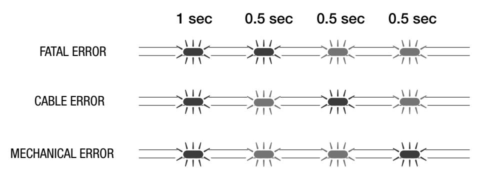
| FATAL ERROR |
Tests core functionality - MCUs, memory and internal
communication, etc. |
|---|---|
| CABLE ERROR |
Tests communication between the different
parts in the system, i.e. different boards connected with a wire. |
| MECHANICAL ERROR | Test related to moving parts of the lock. |