Corbin Russwin IN100 Series with ED5000 Series ED5200(S)N, ED5600N Exit Devices Rim and Mortise Installation Ins…_FM431
Open the original PDF document
View PDFInstallation Instructions

ED5200(S)N & ED5600N Series with Aperio ™ Technology
Exit Devices - Includes Rim and Mortise
WARNING
This product can expose you to lead which is known to the state of California to cause cancer and birth defects or other reproductive harm. For more information go to www. P65warnings.ca.gov.
AVERTISSEMENT
Ce produit peut vous exposer au plomb qui, dans l'état de la Californie, est reconnu pour causer le cancer, des anomalies congénitales ou d'autres problèmes de reproduction. Pour plus d'informations, visitez: www. P65warnings.ca.gov.
WARNING
Attention Installer: Improper installation may result in damage to the product and void the factory warranty.
For installation assistance contact Corbin Russwin 1-800-543-3658 • techsupport.corbinrusswin@assaabloy.com
Exit Devices - Includes Rim and Mortise

Installation Instructions
| TOC | Table of Contents |
|---|---|
| 1 |
Regulatory
4 |
| 2 | Warning 4 |
| 3 | General Description 5 |
| 4 |
Specifi cations / Features
5 |
| a |
Hardware Specifi cations
5 |
| b | Electrical Specifi cations 6 |
| 5 |
Product Illustrations
6 |
| a | RIM/CVR/Mortise 6 |
| 6 | Rim Exit Installation Instructions 8 |
| a | Verify Hand and Bevel of Door 8 |
| b | Prep Door According to Door Marker FM429 8 |
| c | Install Door Position Switch (DPS) 8 |
| d | Trim Assembly Instructions 9 |
| e | Install Exit Device 10 |
| f | Harness Connections (Figure 11) 11 |
| g | Install Head Cover 11 |
| 7 | Install Door 12 |
| a | Verify Hand and Bevel of Door 12 |
| b | Prep door according to supplied door markers 12 |
2
Exit Devices - Includes Rim and Mortise

Installation Instructions
| TOC | Table of Contents, continued |
|---|---|
| c | Install Door Position Switch (DPS). (Figure 16) 12 |
| d | Install Mortise and Outside Trim Assembly13 |
| e | Install Exit Device13 |
| f | Harness Connections (Figure 21) 14 |
| g | Install Head Cover 14 |
| 8 | IN100 Installation Instructions 15 |
| a | Install Outside (Reader) Escutcheon and Inside Mounting Plate 15 |
| b | Installation of Connectors 16 |
| c | Install Inside Module Component Assembly 17 |
| d | Battery Installation 17 |
| e | Inside Cover Installation (Figure 33) 18 |
| 9 | Operational Check 18 |
| 10 | Communication Hub LED Indications 19 |
| 11 | Lock LED Indications 20 |
| 12 | Lock Self-Test LED Indications21 |
| 13 | Lock Busy LED Indications22 |
and Egress Hardware Group, Inc. is prohibited.
Reproduction in whole or in part without the express written permission of ASSA ABLOY Access
Exit Devices - Includes Rim and Mortise
Installation Instructions


1 Regulatory Compliance
Changes or modifi cations to this unit not expressly approved by the party responsible for compliance could void the user's authority to operate the equipment.
FCC:
This equipment has been tested and found to comply with the limits for a Class B digital device, pursuant to Part 15 of the FCC Rules. These limits are designed to provide reasonable protection against harmful interference in a residential installation. This equipment generates, uses, and can radiate radio frequency energy and, if not installed and used in accordance with the instructions, may cause harmful interference to radio communications. However, there is no guarantee that interference will not occur in a particular installation. If this equipment does cause harmful interference to radio or television reception, which can be determined by turning the equipment off and on, the user is encouraged to try to correct the interference by one or more of the following measures:
- Reorient or relocate the receiving antenna.
- Increase the separation between the equipment and receiver.
- Connect the equipment into an outlet on a circuit different from that to which the receiver is connected.
- Consult the dealer or an experienced radio/TV technician for help.
Industry Canada:
This Class B digital apparatus meets all requirements of the Canadian Interference Causing Equipment Regulations. Operation is subject to the following two conditions: (1) this device may not cause harmful interference, and (2) this device must accept any interference received, including interference that may cause undesired operation.
Cet appareillage numérique de la classe B répond à toutes les exigences de l'interférence canadienne causant des règlements d'équipement. L'opération est sujette aux deux conditions suivantes: (1) ce dispositif peut ne pas causer l'interférence nocive, et (2) ce dispositif doit accepter n'importe quelle interférence reçue, y compris l'interférence qui peut causer l'opération peu désirée.
This equipment complies with FCC radiation exposure limits set forth for an uncontrolled environment. This equipment should be installed and operated with minimum distance 20cm between the radiator and your body. This transmitter must not be co-located or operating in conjunction with any other antenna or transmitter.
Cet équipement est conforme aux limites d'exposition aux radiations de la FCC définies pour un environnement non contrôlé. Cet équipement doit être installé et utilisé à une distance minimale de 20 cm entre le radiateur et votre corps. Cet émetteur ne doit pas être co-localisé ou fonctionner en conjonction avec une autre antenne ou un autre émetteur.
Under Industry Canada regulations, this radio transmitter may only operate using an antenna of a type and maximum (or lesser) gain approved for the transmitter by Industry Canada. To reduce potential radio interference to other users, the antenna type and its gain should be so chosen that the equivalent isotropically radiated power (e.i.r.p.) is not more than that necessary for successful communication.
Conformément à la réglementation d'Industrie Canada, le présent émetteur radio peut fonctionner avec une antenne d'un type et d'un gain maximal (ou inférieur) approuvé pour l'émetteur par Industrie Canada. Dans le but de réduire les risques de brouillage radioélectrique à l'intention des autres utilisateurs, il faut choisir le type d'antenne et son gain de sorte que la puissance isotrope rayonnée équivalente (p.i.r.e.) ne dépasse pas l'intensité nécessaire à l'établissement d'une communication satisfaisante.
2 Warning

This product can expose you to lead which is known to the state of California to cause cancer and birth defects or other reproductive harm. For more information go to: www.P65warnings.ca.gov.
Ce produit peut vous exposer au plomb qui, dans l'état de la Californie, est reconnu pour causer le cancer, des anomalies congénitales ou d'autres problèmes de reproduction.
Pour plus d'informations, visitez: www.P65warnings.ca.gov.

Any retrofit or other field modification to a fire rated opening can potentially impact the fire rating of the opening, and Corbin Russwin makes no representations or warranties concerning what such impact may be in any specific situation. When retrofitting any portion of an existing fire rated opening, or specifying and installing a new fire-rated opening, please consult with a code specialist or local code official (Authority Having Jurisdiction) to ensure compliance with all applicable codes and ratings.

To avoid possible damage from electrostatic discharge (ESD), some basic precautions should be used when handling electronic components:
- Minimize build-up of static by touching and/or maintaining contact with unpainted metal surfaces such as door hinges, latches, and mounting plates especially when mounting electronic components such as readers and controllers onto the door.
- Leave components (reader and controller) protected in their respective anti-static bags until ready for installation
- Do not touch pins, leads or solder connections on the circuit boards
Exit Devices - Includes Rim and Mortise
Installation Instructions

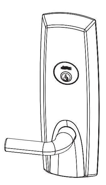
3 General Description
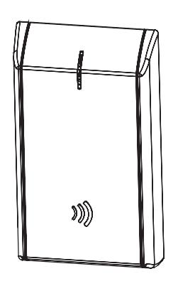
The Corbin Russwin® IN100 lock with Aperio™ Technology makes it easy and cost-effective to bring access control to more doors. It uses local wireless communication between the lock and an Aperio hub to connect to an access control system, eliminating the greatest cost and inconvenience of traditional access control – the wiring at the door. The IN100 utilizes HID® multiCLASS SE® technology; it supports heightened identity security and multiple credentials, including mobile access.
All technology features are supported by the physical security of Corbin Russwin ANSI/BHMA Grade 1 hardware - quality components that provide high security, performance and durability.

4 Specifi cations / Features

a Hardware Specifi cations
- Latch Stainless steel, 3/4" (19mm) throw deadlocking fire latch
- Deadlocking latch prevents manipulation when door closed
- Door Thickness 1-3/4" (44mm) to 2" (50mm) Standard Optional 2" (50mm) to 2-1/4" (57mm) optional
- ADA Compliant
- ANSI/BHMA A156.25 Listed Grade 1 Compliant
-
May be used for indoor and outdoor* applications
- *A weather-protective gasket is required for outdoor applications.

b Electrical Specifi cations
- Input Power: DC 9V, 1.5A (6 AA alkaline batteries)
- Optional hard-power 12-24VDC, 1.0A
-
HID® multiCLASS SE® technology offers support for the following credentials:
-
High Frequency (13.56 MHz):
- HID iCLASS®
- HID iCLASS SE® (SIO-enabled)
- HID iCLASS® Seos™
- HID MIFARE® SE
- HID DESfire® EV1 SE
- MIFARE Classic
- DESfire EV1
- Low Frequency (125 kHz):
- HID Prox®, AWID, EM4102
- NFC & BLE-enabled Mobile Phones
-
High Frequency (13.56 MHz):
- Utilizes IEEE 802.15.4 wireless communication
- Multiple time zone and holiday access scheduling
- First-in unlock or automatic unlock configuration, based on specified time schedule
- Uses AES 128-bit wireless encryption**
- Privacy button
** For specific security information, please contact your local ASSA ABLOY Door Security Solutions sales consultant or call 800-810-WIRE.
Exit Devices - Includes Rim and Mortise
Installation Instructions
5 Product Illustrations
a Rim/CVR/Mortise
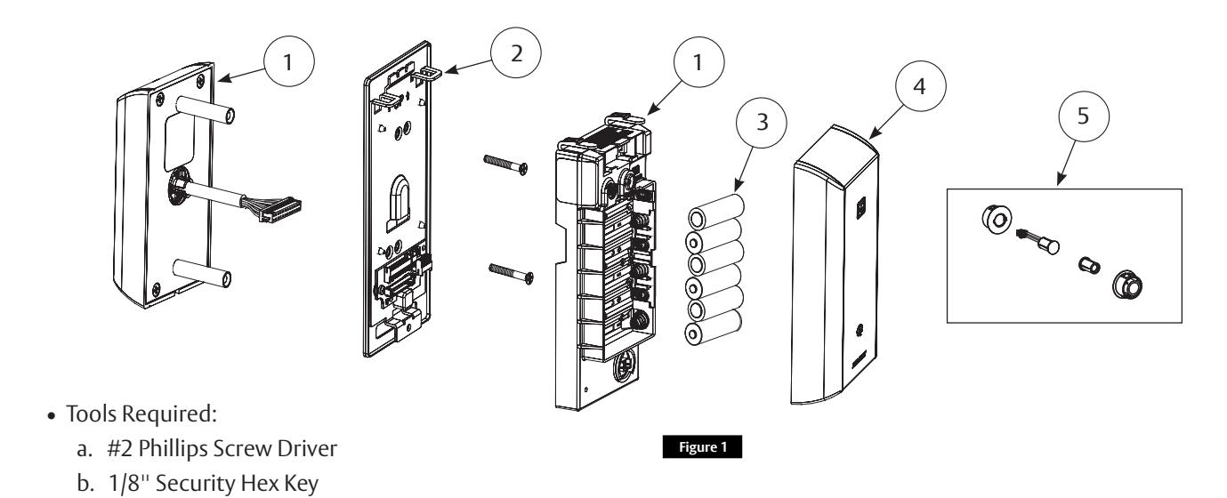
*9133, 9134, 9M133, 9M134 (Example: IN-100-EM019133-IP-B)
Note: Escape Return functionality is not available with IN100 Series Exit Devices.
| Item | Part Number / Order String | Description | Color / Trim | Qty. |
|---|---|---|---|---|
| IN-100-EM01[locktype]*-BIPS-B | Black | 1 | ||
| 1 | IN-100-EM01[locktype]*-BIPS-W | White | 1 | |
| IN-100-EM01[locktype]*-BIPS-MB-[specify finish] |
Reader featuring multiCLASS technology
Black w/metal trim |
1 | ||
| IN-100-EM01[locktype]*-BIPS-MW-[specify finish] | White w/metal trim | 1 | ||
| 2 | 820F558 | Inside Mounting Kit (mounting plate & hardware) | 1 | |
| 3 | N/A | AA battery | 6 | |
| 4 | 820F489 | Inside Escutcheon Cover | Black | 1 |
| 820F499 | Inside Escutcheon Cover | White | ||
| 820F525 [specify finish] | Inside Escutcheon Cover | Black w/metal trim | ||
| 820F535 [specify finish] | Inside Escutcheon Cover | White w/metal trim | ||
| 5 | 820F609 | Door Position Switch Kit (SPDT) | 1 | |
Exit Devices - Includes Rim and Mortise

Installation Instructions
5 Product Illustrations, continued
a Rim/CVR/Mortise
| Item | Part Number / Order String | Description | Color / Trim | Qty. |
|---|---|---|---|---|
| FM429 | Field prep template - Exit Rim (not shown) | 1 | ||
| FM430 | Field prep template - Exit Mortise (not shown) | 1 | ||
| T31235 | Door manufacturers template - Exit Rim (not shown) | 1 | ||
| T31236 | Door manufacturers template - Exit Rim (not shown) | 1 | ||
| T31237 | Door manufacturers template Exit Mortise (not shown) | 1 | ||
| FM431 | Instructions (this manual) | 1 |
and Egress Hardware Group, Inc. is prohibited.
Reproduction in whole or in part without the express written permission of ASSA ABLOY Access
Exit Devices - Includes Rim and Mortise
Installation Instructions


6 Rim Exit Installation Instructions

a Verify Hand and Bevel of Door
- 1. Door should be fitted and hung.
- 2. Verify box label for size of exit device, function, and hand.
b Prep Door According to Door Marker FM429
• For door manufacturer templates visit www.corbinrusswin.com
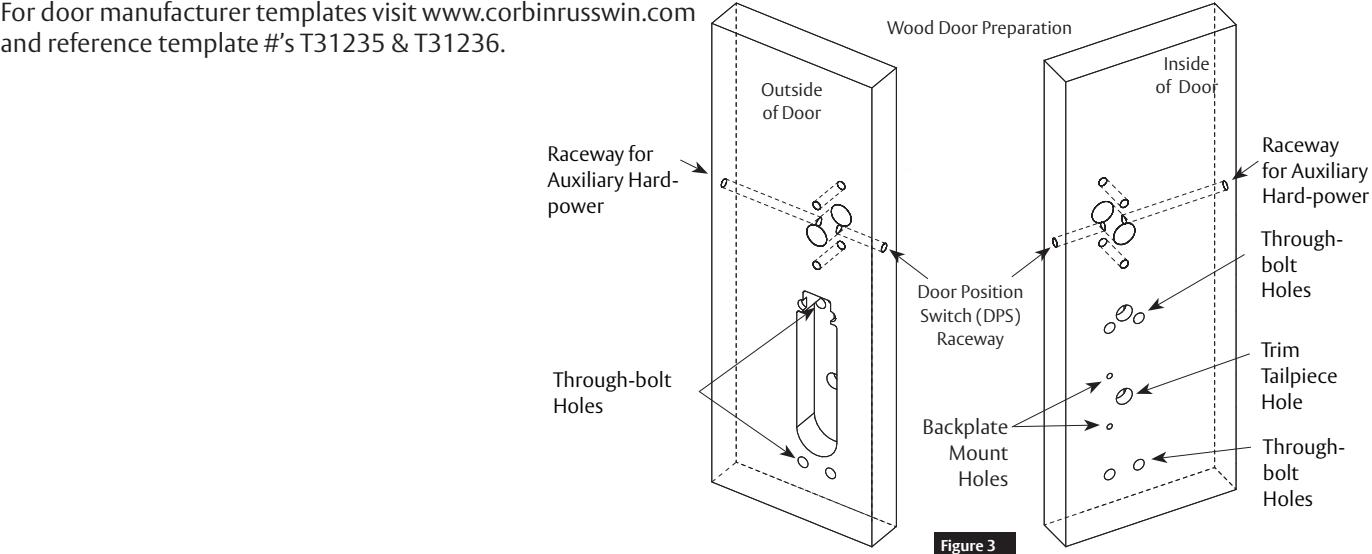

c Install Door Position Switch (DPS)
- 1. Insert DPS into raceway on latch edge of door.
- 2. Push wires through raceway toward lock prep.
- 3. Push DPS firmly into place by hand.
Note: Do Not Tap Switch With Any Tool.
4. Install magnet into door frame. Push firmly into place by hand. See instruction A7983A.

If DPS is not installed or is installed improperly, door status monitoring features will not function.
For installation assistance contact Corbin Russwin
and Egress Hardware Group, Inc. is prohibited.
1-800-543-3658 • techsupport.corbinrusswin@assaabloy.com Copyright © 2022, ASSA ABLOY Access and Egress Hardware Group, Inc. All rights reserved. Reproduction in whole or in part without the express written permission of ASSA ABLOY Access
FM431 12/22
Exit Devices - Includes Rim and Mortise
Installation Instructions

6 Rim Exit Installation Instructions, continued

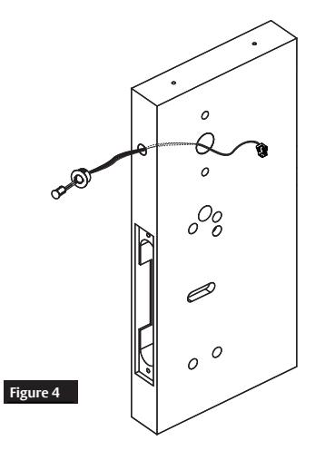
d Trim Assembly Instructions
-
1. Check cylinder components.
- Cylinders longer than 1-1/8" (29mm) require collars.
Refer to Cylinder Collar Chart. (Figure 5)
Note: For Mortise, skip to Step e.
-
2. If required, modify by cutting cylinder tailpiece:
- Correct length is 1/16" to 3/16" (2 to 5mm) beyond cylinder housing cam.
-
3. Assemble cylinder:
- a. Insert cylinder housing prongs into matching notches of escutcheon.
- b. Pass cylinder tailpiece through cylinder collar (if required) and slot in cylinder cam.
- c. Fasten cylinder in escutcheon recess or collar using two (2) mounting screws. Do not overtighten screws.
- 4. Escutcheon Assembly (Figure 6):
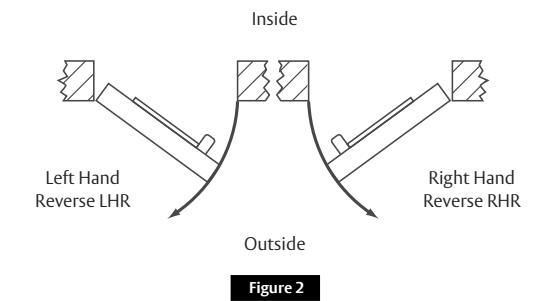
Lever is handed (LHR shown).
Note: Lever return spring handing can be identified by color of spring:
- LHR: Part Number 651F618 (Red)
- RHR: Part Number 651F628 (Blue)
| Cylinder Collar Chart | ||
|---|---|---|
| Cylinder Length | Collar | |
| Inches | Millimeters | |
| 1-1/8" | 29mm | None |
| 1-1/4" | 32mm | 422F88* |
| 1-1/2" | 38mm | 686F98* |
| *Specify Finish | ||
Figure 5

Exit Devices - Includes Rim and Mortise
Installation Instructions

6 Rim Exit Installation Instructions, continued

e Install Exit Device
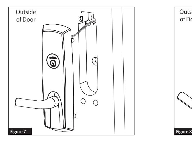
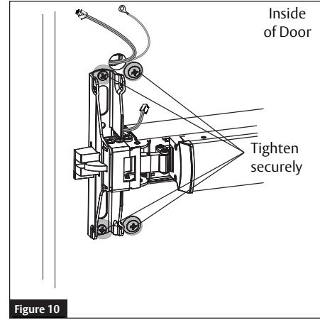
- 1. Feed trim harness and ground wire through upper hole in cutout. (Figure 7).
- 2. Seat device against door being careful to align vertical trim tailpiece to engage with cross hole of device cam. (Figure 8).
- 3. Fasten device to trim assembly using two (2) 1/4-20 pan head screws. (Figure 9)
- 4. Follow instructions packed with device to secure device to door.
- 5. Tighten all four (4) screws. (Figure 10)

When installing trim, pull wires completelythrough door to avoid contacting motor assembly, as this may cause loss of function.


Exit Devices - Includes Rim and Mortise
Installation Instructions
6
Rim Exit Installation Instructions, continued

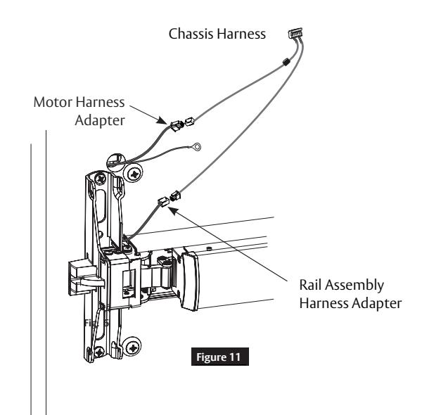
f Harness Connections (Figure 11)
- 1. Connect motor harness adapter to chassis harness connector.
- 2. Connect rail assembly harness adapter to chassis harness connector.
g Install Head Cover
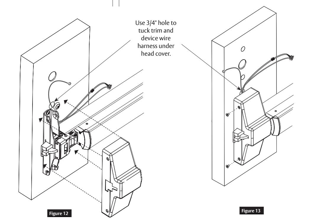
- 1. Lay device wire harnesses across 3/4" hole. (Figure 12)
- 2. Fold excess wires next to latch assembly.
Note: Avoid feeding excess wires back through the door as they may interfere with trim operation.
3. Attach head cover using two (2) #8-32 flat head screws. (Figure 13)
Note: Take care not to pinch wires between cover and door.
Important Note: Rim Exit Installation Continues with Section 8, IN100 Installation Instructions
Exit Devices - Includes Rim and Mortise
Installation Instructions


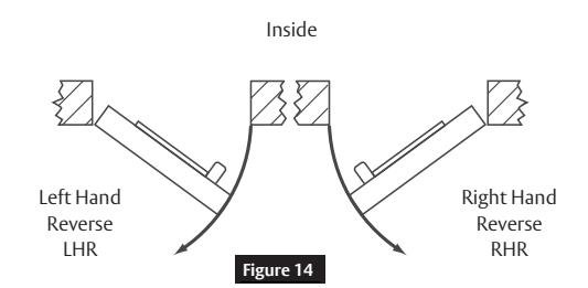
Verify Hand and Bevel of Door (Figure 14)
- 1. Door should be fitted and hung.
- 2. Verify box label for size of exit device, function and hand.
ASSA ABLO

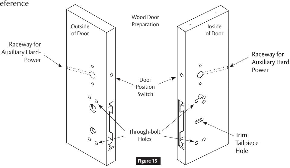
V Prep Door According to Door Marker FM430 (Figure 15)
Note: For door manufacturer templates, visit www.corbinrusswin.com and reference template #T31237 (Wood).
12

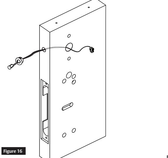
Install Door Position Switch (DPS). (Figure 16)
- 1. Insert DPS into raceway on latch edge of door.
- 2. Push wires through raceway toward lock prep.
- 3. Push DPS firmly into place by hand.
Do not tap switch with any tool.
4. Install magnet into door frame. Push firmly into place by hand. See instruction A7983.
Caution: If DPS is not installed or is installed improperly, door status monitoring features will not function.
For installation assistance contact Corbin Russwin 1-800-543-3658 • techsupport.corbinrusswin@assaabloy.com
Copyright © 2022, ASSA ABLOY Access and Egress Hardware Group, Inc. All rights reserved. Reproduction in whole or in part without the express written permission of ASSA ABLOY Access and Egress Hardware Group, Inc. is prohibited.
FM431 12/22
Experience a safer and more open world
Exit Devices - Includes Rim and Mortise
Installation Instructions
7
Mortise Exit Installation Instructions, continued
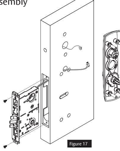
d Install Mortise and Outside Trim Assembly
- 1. Ensure tailpiece is oriented vertically.
- 2. Feed trim wire harness through wire harness hole. (Figure 17)
-
3. Mount trim assembly to door pulling slack wire towards device side of door.
- Note: Be careful not to pinch wire harness.
- 4. Fasten trim assembly to door using two (2) 1/4-20 oval head screws and two (2) finish washers. (Figure 18)
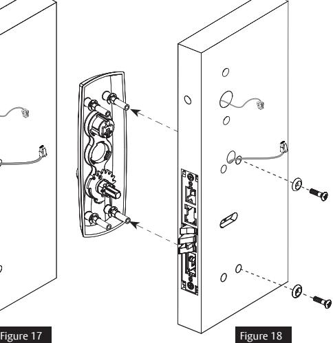
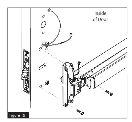
e Install Exit Device
- 1. Seat device against door being careful to align vertical trim tailpiece to engage with cross hole of device cam. (Figure 19)
- 2. Fasten device to trim assembly using two (2) 1/4-20 pan head screws. (Figure 19)
- 3. Follow instructions packed with device to secure device to door.
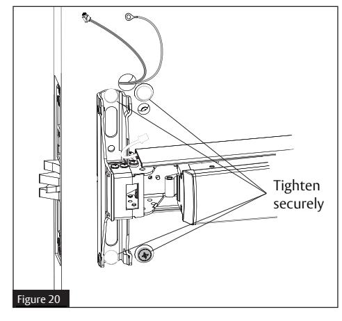
- 4. Tighten all four (4) screws. (Figure 20)
Exit Devices - Includes Rim and Mortise
Installation Instructions

Mortise Exit Installation Instructions, continued

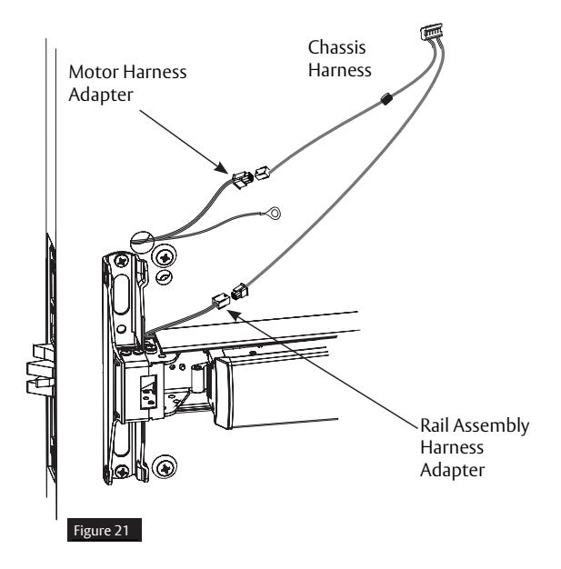
f Harness Connections (Figure 21)
- 1. Connect motor harness adapter to chassis harness connector.
- 2. Connect rail assembly harness adapter to chassis harness connector.
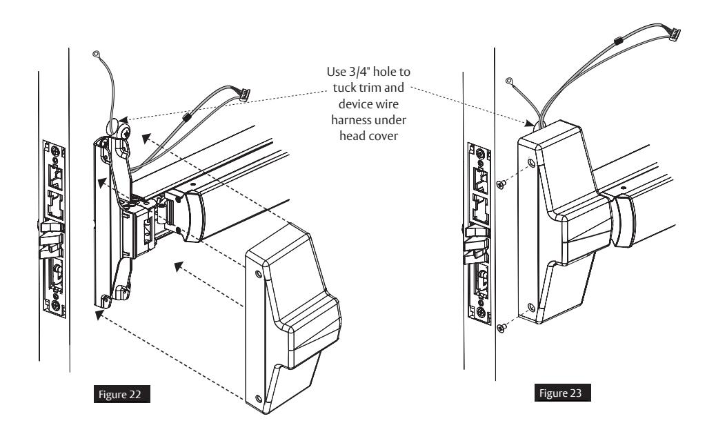
g Install Head Cover
- 1. Lay device wire harnesses across 3/4" hole. (Figure 22)
- 2. Attach head cover using two (2) #8-32 flat head screws. (Figure 23).
- 3. Take care not to pinch wires between cover and door.
FM431 12/22
Exit Devices - Includes Rim and Mortise
Installation Instructions

8
IN100 Installation Instructions

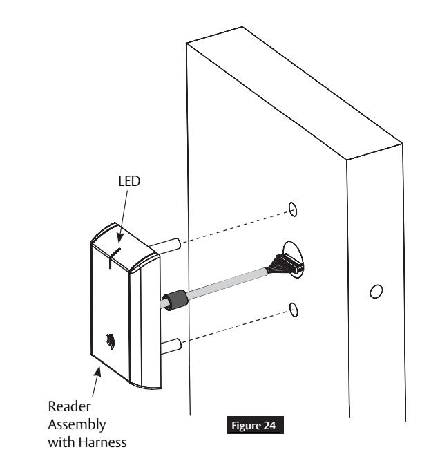
a Install Outside (Reader) Escutcheon and Inside Mounting Plate
- 1. Orient reader so LED lens is at top. (Figure 24)
- 2. Feed cable/connector through door from outside to inside.
- 3. Install reader to outside of door by aligning mounting posts with door preparation holes. Hold reader flush against door while ensuring proper alignment.
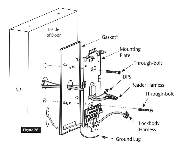
- 4. Feed reader harness and DPS connectors through inside mounting assembly and gasket if required*. (Figure 25)
Note:
- Do not run wires through bottom flange hole in plate - it will damage wires and controller connector. (Figure 25, Figure 26)
- Route wires around flange, do not route wires through flange hole. (Figure 25)
- 5. Tuck excess cable into wire hole on inside of door.
- 6. Begin to secure mounting assembly by partially tightening two (2) through-bolts on inside of door while ensuring proper alignment as reader is secured. (Figure 25)
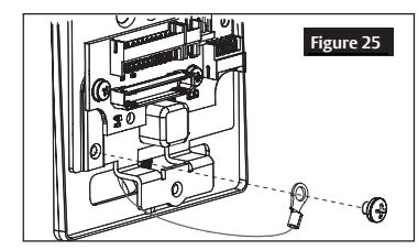
- 7. Secure ground lug with #6-32 machine screw. (Figure 26)
Notes:
- Gasket is required for outdoor installations
- Do not use gasket for fire-rated openings
- If installing with gasket, separate gasket from mounting plate to feed cables/connectors through holes as indicated (Figure 25)
- Once cables/connectors are fed through, reattach gasket to mounting plate
Note: Cable lengths exaggerated for illustrative purposes.
Exit Devices - Includes Rim and Mortise
Installation Instructions

8
IN100 Installation Instructions, continued

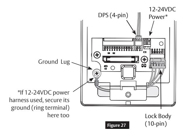
b Installation of Connectors
1. Secure the following connectors to their respective terminals. (Figure 27)

Do not touch or allow debris to enter connector contacts.
- Secure 4-pin DPS connector.
- Secure 10-pin lock body assembly connector.
Note: Optional 2-pin external 12-24VDC power connector.

Do not run wires through bottom hole in plate - it will damage wires and controller connector.
Route wires around flange, do not route wires through flange hole. (Figure 26, Figure 28).
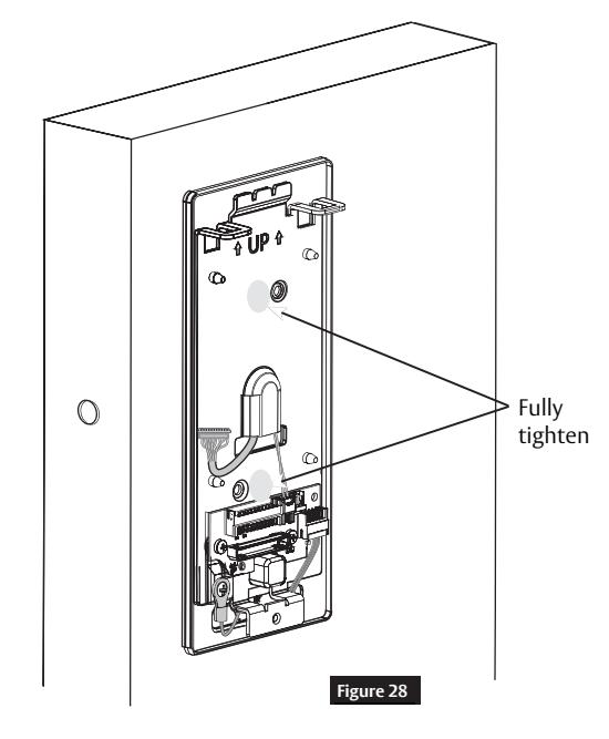
- 2. When all connections have been made, tuck excess cable into wire hole on inside of door.
- 3. Secure mounting assembly while ensuring proper alignment of outside reader and tighten two (2) through-bolts on inside of door to secure reader. (Figure 28)
- 4. Secure 24-pin card reader connector. (Figure 29)
|
Board-to-Board
Connector Figure 29 |
|---|
| Optional 12-24VDC Power* | ||
|---|---|---|
| Remote Power Harness Wire Terminations | ||
| 2-pin | Red | PS (-) Return |
| Connector | Black | PS (+) 12-24VDC |
| Ring Terminal | Green | Earth Ground |
| *Power Supply (PS) Required - UL Class 2 Filtered & Regulated, 12-24VDC, 1.0A | ||
FM431 12/22
Exit Devices - Includes Rim and Mortise
Installation Instructions

IN100 Installation Instructions, continued

c Install Inside Module Component Assembly
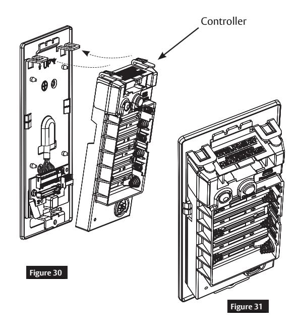
- 1. Insert bottom tab of controller (make sure path is clear) into slot on mounting plate. (Figure 30)
- 2. Ensure proper alignment of board-to-board connectors while pivoting controller toward door until two tabs on top snap securely into place on mounting plate. (Figure 31)

To avoid possible damage to board-to-board connectors, care should be taken when securing controller to mounting plate.
If there is resistance when securing, detach controller to determine cause before re-attaching controller.
d Battery Installation
- 1. Place six (6) "AA" alkaline batteries in compartment, being careful to align polarity properly. (Figure 32)
- 2. After batteries are installed, there is a slight delay; then red and green flash*, audible "beep" and lock motor will cycle.
*See Section 9 - LED Indications for more information.

Exit Devices - Includes Rim and Mortise
Installation Instructions
8
IN100 Installation Instructions, continued

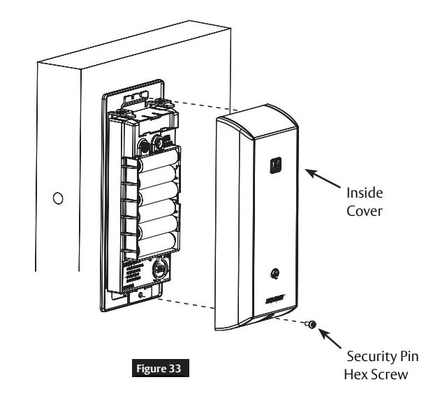
e Inside Cover Installation (Figure 33)
- 1. Assemble cover by hooking top edge on inside mounting plate.
- 2. Carefully press bottom of cover toward door without pinching or damaging wires.
- 3. Secure cover utilizing 1/8" security hex key
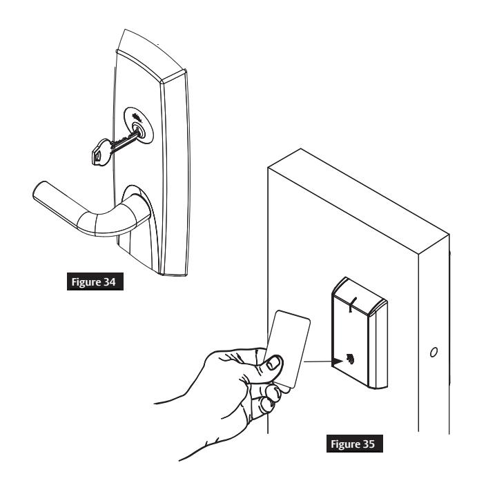
9 Operational Check
- 1. Insert key into cylinder and rotate. (Figure 34) Note: There should be no friction against lock case, wire harness or any other obstructions.
-
2. Check that key retracts latch.
- Note: Key should rotate freely.
- 3. Try inside lever; ensure it retracts latch.
- 4. Present a valid credential* to unlock outside lever; turn lever handle to ensure latch retracts. (Figure 35)
Note: Credential should approach inscription on reader as indicated to ensure credential is read properly. Do not wave credential. (Figure 35)
*Depending upon availability of access control system either a (denied) red flash or a green and lock motor cycle (access granted).
Exit Devices - Includes Rim and Mortise
Installation Instructions
10 Communication Hub LED Indications
Communication hub has a single LED. It supports an optical scheme of red, green and yellow. Indication scheme is described by figures below:
Communication Hub NORMAL OPERATION LED indication
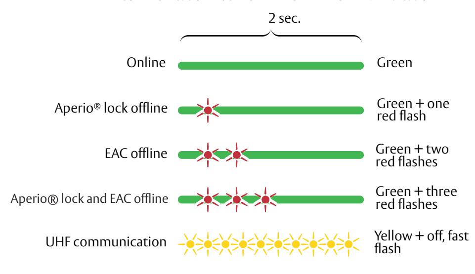
Some special LED indication schemes are used during lock maintenance actions:
Communication Hub MAINTENANCE LED indication

LED on AH40 communication hub indicates both status of Ethernet link level and ethernet communication:
AH40 Communication Hub ETHERNET LED indication
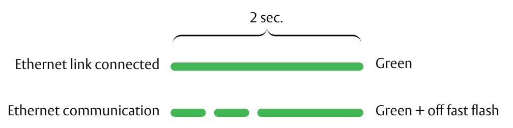
*For more information, refer to Aperio Online Quick Installation Guide, Document No: ST-001322-PF
Exit Devices - Includes Rim and Mortise
Installation Instructions
11 Lock LED Indications
Lock has three (3) LEDs. They support an optical scheme with red, yellow and green. Indication scheme described by figures below:
Lock NORMAL OPERATION LED indication
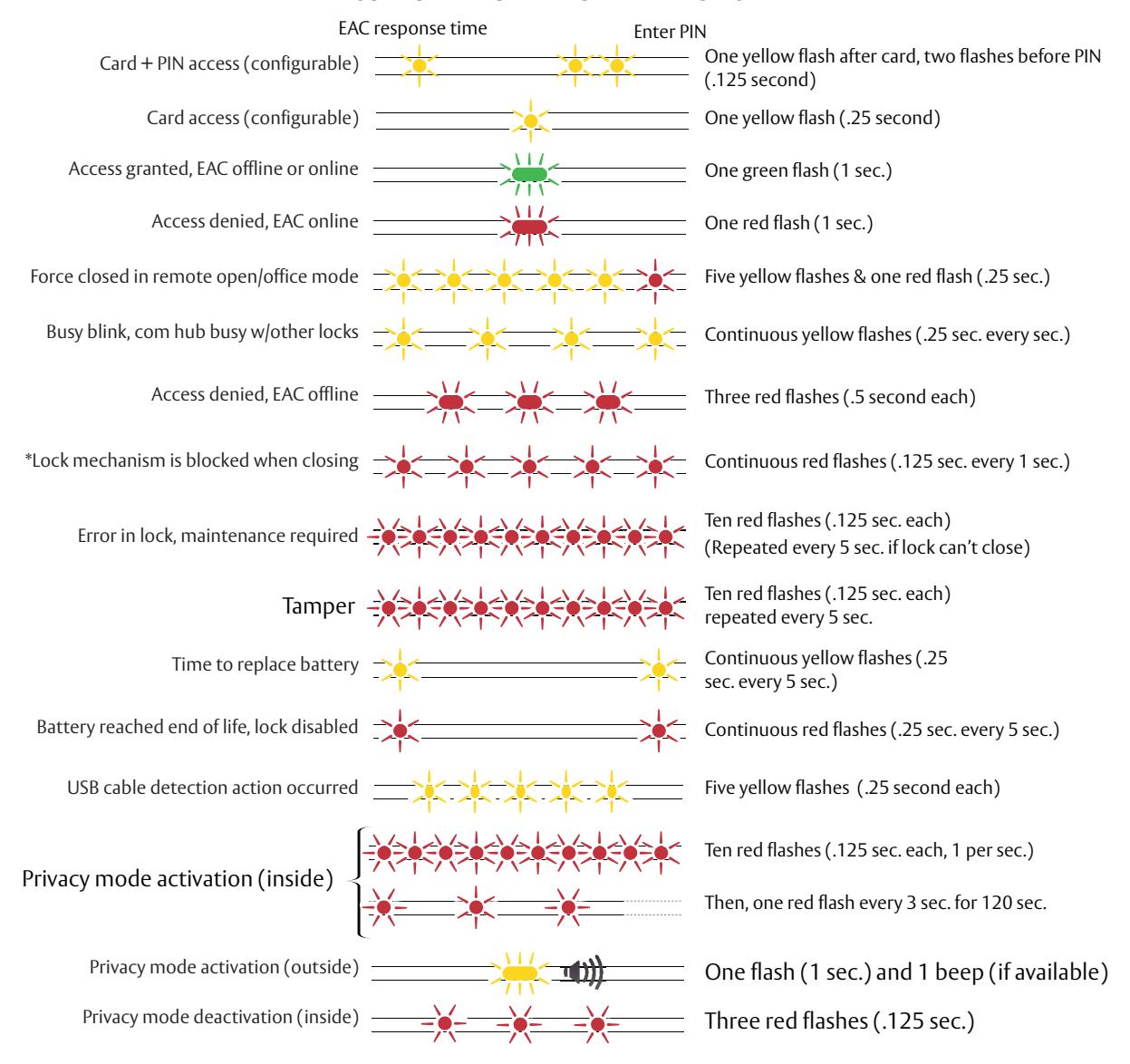
*When lock mechanism is blocked (lock jammed) lever must be turned to release lock mechanism.

Some special LED indication schemes are used during lock maintenance actions:
Lock MAINTENANCE OPERATION LED indication
Enter configuration mode Five yellow flashes (.125 sec. each)
Exit Devices - Includes Rim and Mortise
Installation Instructions
12 Lock Self-Test LED Indications
After replacing batteries, a Power on Self Test (POST) is performed. The result is indicated using a series of red and green LED flashes as described by figures below:
Battery Not Fully Charged
Error in lock is an indication -10 quick (125ms) red blinks, that either new batteries are not at right voltage or a backward battery has been installed; battery not fully charged; energy counter not reset or no Power on self-test performed.

Ten red flashes (.125 sec. each) (Repeated every 10 sec. if lock can't close)
Test Pass
1 red (1s) + 1 green (1s), Power on self-test passed. See table below.
POST Successful One red, one green flash (1 Second)
Test Fail
1 red (1s) + 3 blinks (500ms, green or red), at least one test failed (red). (See table below)
If a fatal error is detected, lock will enter an Error state and continuously indicate fatal error. Lock will not read cards or unlock.
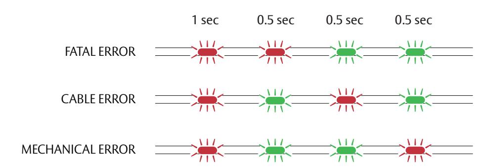
| Fatal Error |
Tests core functionality. MCUs, memory and internal
communication, etc. |
|---|---|
| Cable Error |
Tests communication between different
parts in system, i.e. different boards connected with a wire. |
| Mechanical Error | Test related to moving parts of lock. |
Exit Devices - Includes Rim and Mortise
Corbin Russwin ASSA ABLOY
Installation Instructions
13
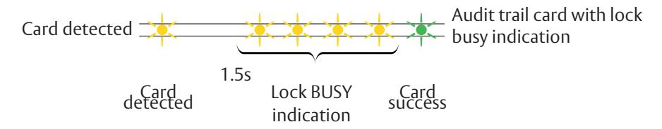
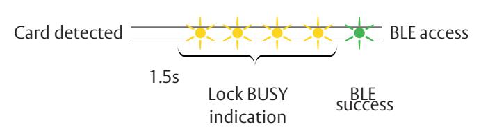
Lock Busy LED Indications
- Lock BUSY indicates lock is processing a card (such as a key configuration card for online SE processor or offline void list card with many entries). Card should be kept in close proximity to reader until end of process.
- Lock BUSY indication does not cancel or overwrite any other indications. Indications related to access permissions or setup card processing are still present. Indication scheme is described by figures below:
Lock BUSY indication

Lock BUSY indication Mixed with Scenario for Offline Audit Trail Card
Online BLE Access
Online SE Keys Setup Card

*Introduced with firmware version 3.8 - in prior firmware versions only "Config card processed" LED indication is displayed.

Exit Devices - Includes Rim and Mortise
Installation Instructions