Corbin Russwin HPSK Push, Pull Paddle Trim for ML2000 Series Mortise Locks Installation Instructions_FM339
Open the original PDF document
View PDFInstallation Instructions
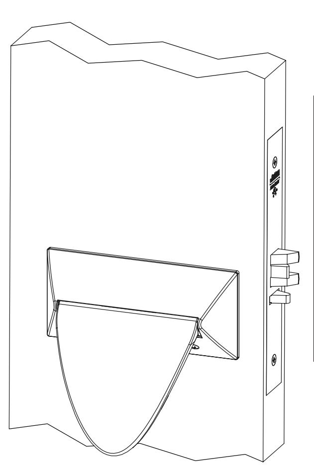
Push/Pull (HPSK) Paddle Trim for ML2000 Series Mortise Locks

| TOC | Table of Contents | |
|---|---|---|
| 1 | Mortise Lock Handing Instructions | .2 |
| 2 | Mortise Lock Door Preparation & Installation | .3 |
| 3 | HPSK Trim Installation | . 5 |
| 4 | Turn-Piece Installation | . 8 |
| 5 | Coin-Turn Installation | .8 |
For installation assistance contact Corbin Russwin 1-888-607-5703 • support@corbinrusswin.com
This product can expose you to lead which is known to the state of California to cause cancer and birth defects or other reproductive harm. For more information go to www.P65warnings.ca.gov.
ML2000 Series Mortise Lock
Installation Instructions

1 Mortise Lock Handing Instructions
- 1. Move the Red locking screw to side of lockbody being locked.
- 2. Push in latch then depress catch plate with screwdriver. (Figure 1)
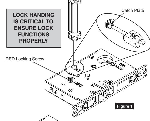
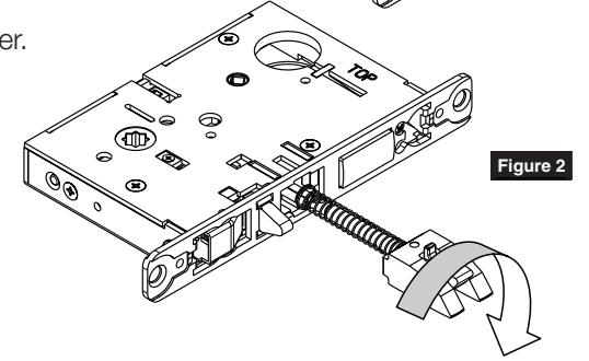
3. Pull latch out of lock-body and turn latch over. (Figure 2)
4. Push in latch while holding screwdriver behind latch tail. (Figure 3)
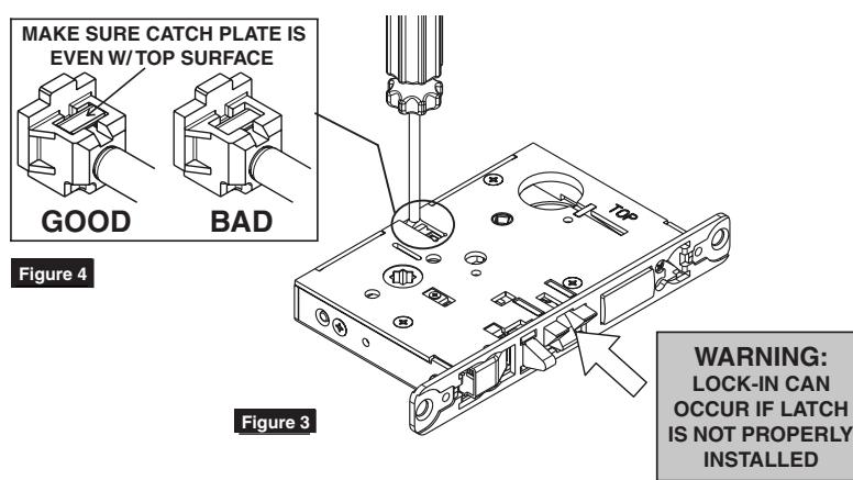
NOTE:
PUSH IN LATCH UNTIL CATCH PLATE IS NO LONGER DEPRESSED. (FIGURE 4)
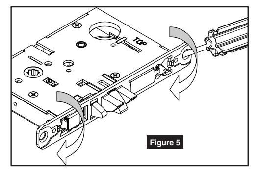
5. Rotate lock front to match bevel of door as shown. (Figure 5)
For installation assistance contact Corbin Russwin 1-888-607-5703 • support@corbinrusswin.com
ML2000 Series Mortise Lock
Installation Instructions

2 Mortise Lock Door Preparation & Installation
Important: Be sure to hand the lockbody before installing. See Section 1.
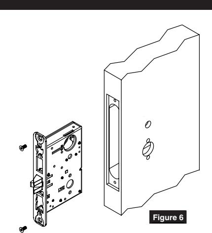
1. Insert mortise lock into door and fully tighten 1" lock mounting combination screws. (Figure 6)

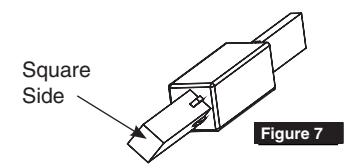
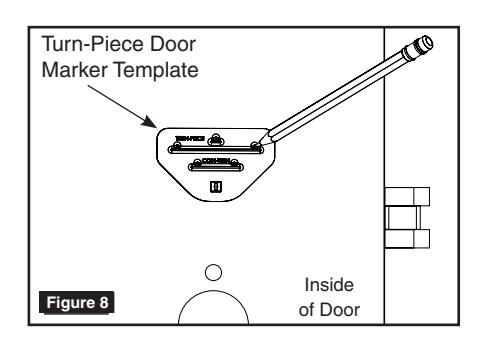
Insert turn-piece door marker spindle into lockbody on inside of door.
NOTE:
USE SQUARE SIDE OF DOOR MARKER SPINDLE. (FIGURE 7)
3. TURN-PIECE FUNCTIONS ONLY: Slide turn-piece door marker over spindle.
4. TURN-PIECE FUNCTIONS ONLY: Mark three holes for turn-piece. (Figure 8)

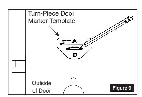
Insert turn-piece marker spindle into lockbody on outside of door.
NOTE:
USE SQUARE SIDE OF DOOR MARKER SPINDLE. (FIGURE 7)
6. COIN-TURN FUNCTIONS ONLY:
Slide turn-piece door marker template over spindle.
7. COIN-TURN FUNCTIONS ONLY:
Mark two holes for coin-turn. (Figure 9)
ML2000 Series Mortise Lock
Installation Instructions

2 Mortise Lock Door Preparation & Installation
8. Remove lockbody from door.
9. TURN-PIECE FUNCTIONS ONLY:
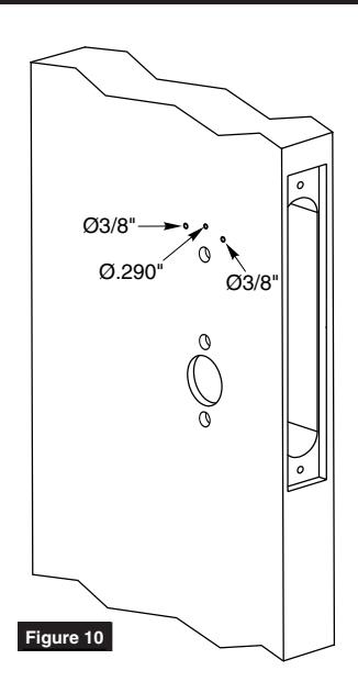
Drill one middle hole (.290") and two outer holes (3/8") halfway through door. (Figure 10)
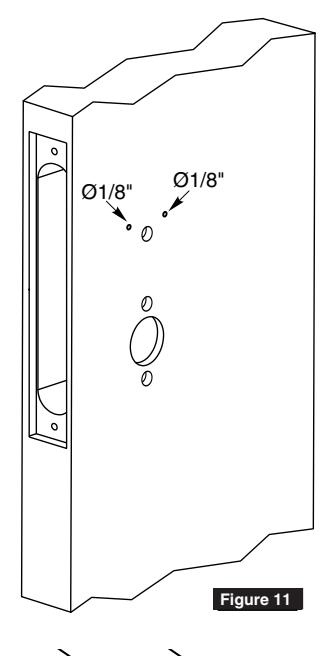
10. COIN-TURN FUNCTIONS ONLY:
Drill two holes (1/8") halfway through door. (Figure 11)
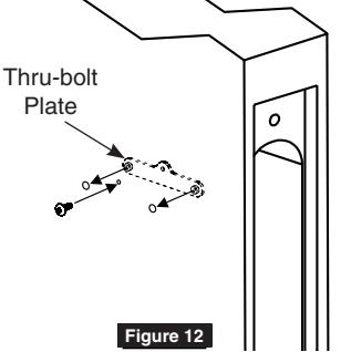
11. TURN-PIECE FUNCTIONS ONLY:
Install turn-piece thru-bolt plate using truss head screw. (Leave screw slightly loose.) (Figure 12)
NOTE:
THE THRU-BOLT PLATE IS INSTALLED INSIDE THE DOOR POCKET.
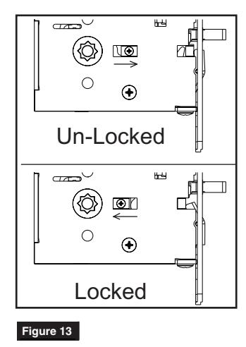
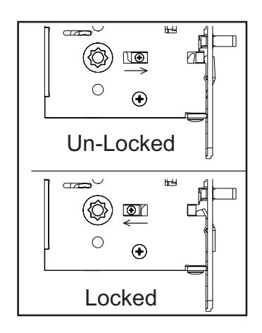
12. Insert mortise lockbody into door and loosely tighten 1" lock mounting combination screws.
NOTE:
MAKE SURE LOCK IS UNLOCKED. (FIGURE 13) MAKE SURE LOCK
ML2000 Series Mortise Lock
Installation Instructions

3 HPSK Trim Installation
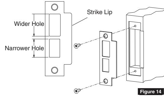
1. Install strike using 3/4" strike mounting screws.
NOTE:
STRIKE MUST BE ORIENTED WITH NARROWER HOLE ON LOWER HALF OF STRIKE AND STRIKE LIP TOWARDS PULL SIDE OF DOOR. (FIGURE 14)
2. CYLINDER FUNCTIONS ONLY:
Slide cylinder(s) through spring and collar, threading into lockbody until cylinder face is flush with collar. (Figure 15)
NOTE:
PULL KEY SLIGHTLY OUT OF CYLINDER TO HELP THREAD INTO LOCKBODY.
NOTE:
CYLINDER MUST BE ORIENTED CORRECTLY. (FIGURE 16)

Install cylinder set screw(s). (Figure 17)
- 4. Fully tighten lock mounting screws.
- 5. Align cam and chassis as shown based on desired paddle orientation. (Figure 18)
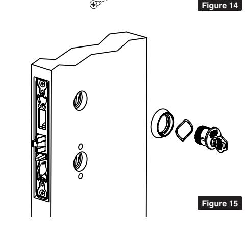
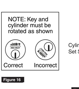
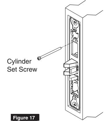
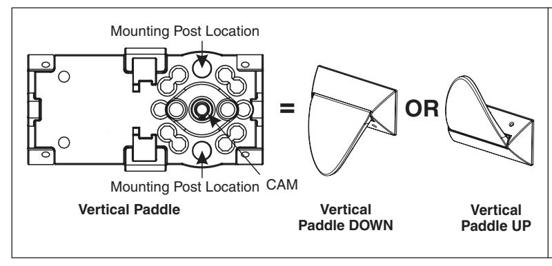
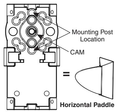
Figure 18
ML2000 Series Mortise Lock
Installation Instructions

3 HPSK Trim Installation
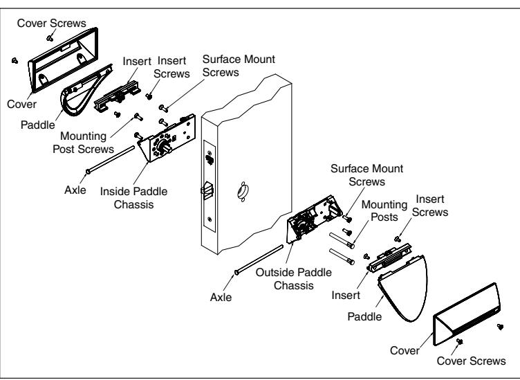
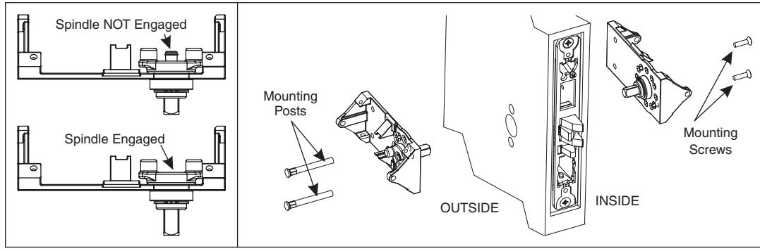
6. Insert mounting posts through outside chassis then install trim on both sides of door using mounting screws (loosely tighten mounting screws). Make sure spindle is fully engaged in lockbody. (Figure 19)
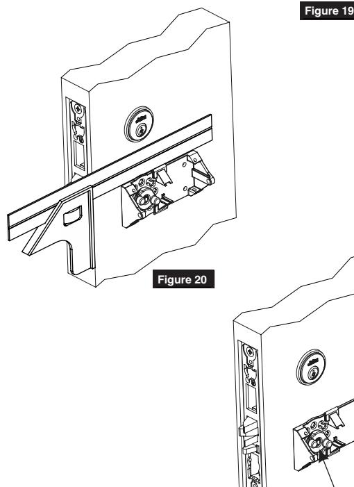
7. Fully tighten 1" lock mounting combination screws then level out chassis using a square. (Figure 20)
NOTE:
USE SQUARE TO LEVEL OUT CHASSIS
- 8. Fully tighten mounting post screws.
- 9. Rotate cam by hand to make sure trim is not binding - latch must project freely when cam is released. If trim binds loosen mounting screws and re-align trim. (Figure 21)
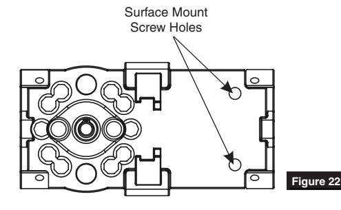
- 10. Install surface mount screws. (Figure 22)
For Wood Door:
- Drill two (2) 7/64" holes for surface mount screws
- Install surface mount wood screws
For Metal Door:
- Drill and tap door for #8-32 screws
- Install surface mount machine screws
FM339 10/18
CAM
Figure 21
ML2000 Series Mortise Lock
Installation Instructions

3 HPSK Trim Installation
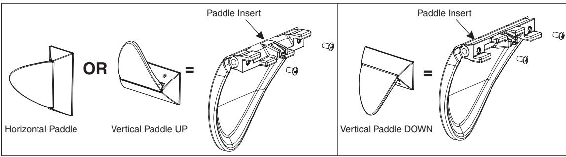
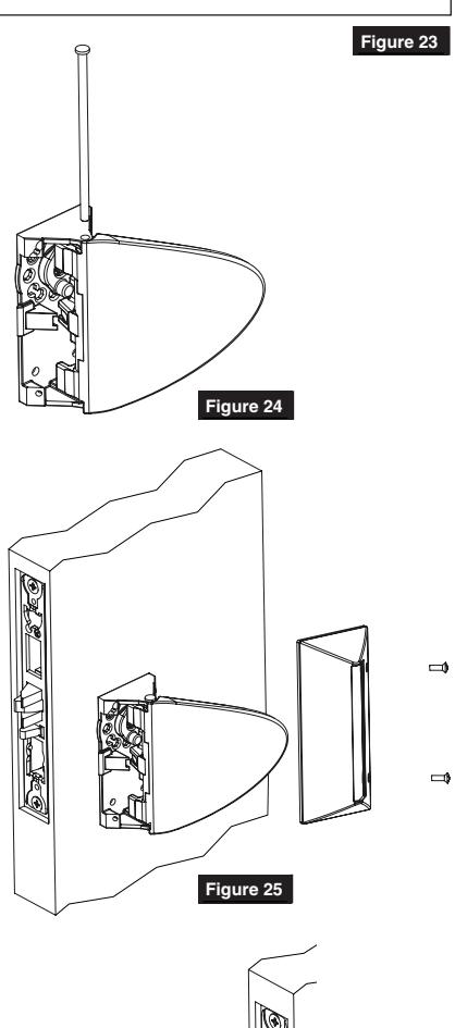
11. Install insert on paddle based on desired paddle orientation. (Figure 23)
12. Attach paddle to chassis by aligning paddle as shown then insert axle through pivot hole in chassis. (Figure 24)

CAUTION:
- SCREWS MUST BE POSITIONED BEHIND PADDLE TO WORK PROPERLY
- Cover will be very difficult to remove if forced on backwards Figure 25
NOTE:
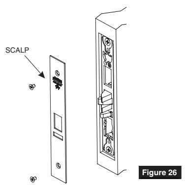
COVER HOOKS UNDERNEATH CHASSIS ON SIDE OPPOSITE MOUNTING SCREWS SCALP
14. Install scalp using 3/16" Flat Head Screws. (Figure 26)
FM339 10/18

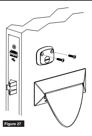
4 Turn-Piece Installation
1. Install turn-piece loosely using two (2) turn-piece mounting screws. (Figure 27)
NOTE:
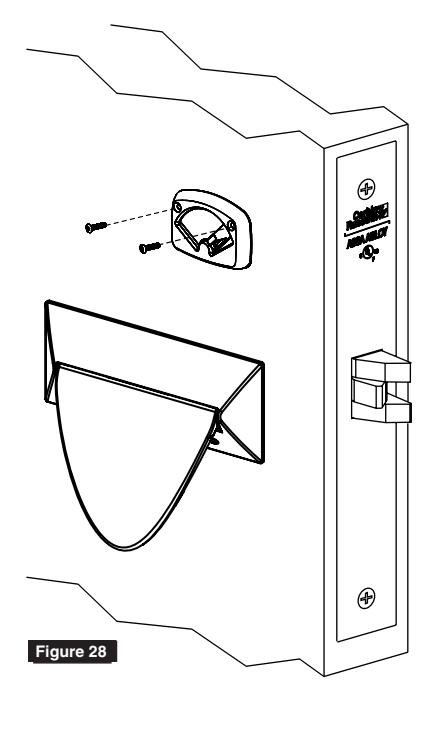
MAKE SURE LOCK IS UNLOCKED AND TURN-PIECE IS ROTATED TOWARDS LATCH. (FIGURE 28)
2. Adjust location of turn-piece on door until turn-piece rotates easily, then fully tighten mounting screws.
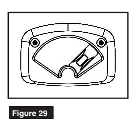
Coin-Turn Installation
1. Install coin-turn using two surface mount screws. (Figure 29)
Corbin Russwin 225 Episcopal Road Berlin, CT 06037 Phone: 800-543-3658 Fax: 800-447-6714 corbinrusswin.com
ASSA ABLOY is the global leader in door opening solutions, dedicated to satisfying end-user needs for security, safety and convenience
Copyright © 2017 Corbin Russwin, Inc., an ASSA ABLOY Group company. All rights reserved. Reproduction in whole or in part without the express written permission of Corbin Russwin, Inc. is prohibited.
For installation assistance contact Corbin Russwin 1-888-607-5703 • support@corbinrusswin.com