Corbin Russwin Electrical Wiring and Wire Routing for PED4000 and PED5000 Series Narrow and Wide Stile M91, M92,…_FM575
Open the original PDF document
View PDFInstallation Instructions

PED4000/PED5000 Series Exit Devices
Electrical Wiring and Wire Routing for:
- M91 Prefix (Latch Monitor Switch)
- M93 Prefix (Exit Trim Lever Monitor Switch)
- M92 Prefix (Push Bar Signal Switch)
- M97 Prefix (Electric Dogging)
- 910/A, 930/A, 903/A, 905/A (Electromechanical Wide Exit Trim)

This product can expose you to lead which is known to the state of California to cause cancer and birth defects or other reproductive harm. For more information go to www.P65warnings.ca.gov.
with optional connections
Installation Manual

| TOC | Table of Contents | |
|---|---|---|
| 1 | Function 3 | |
| 2 | General Description | 3 |
| 3 | Specifications 3 | |
| 4 | ElectroLynx Connector System Notes 4 | |
| 5 | Wire Routing 5 | |
| 6 | PED4000/PED5000 Series Device Installation and Wiring Overview | 16 |
| 7 | M91 Prefix (Latch Monitor Switch) - Exit Device to Frame Connection | 17 |
| 8 | M93 Prefix (Trim Monitor Switch) - Exit Device to Frame Connection | 18 |
| 9 | M92 Prefix Push Bar (Signal Switch) - Exit Device to Frame Connection | 19 |
| 10 | M97 Prefix (Electric Dogging) - Exit Device to Frame Connection | 20 |
| 11 |
910/A, 930/A, 903/A, 905/A (Electromechanical Exit Trim) -
Exit Device to Frame Connection 21 |
|
| 12 | Appendix A: Harness Wiring Reconfiguration | 23 |
Note: The M92, M91, M97, 910/A, 930/A, 903/A, 905/A, and M93 options are combined into this one instruction.
with optional connections
Installation Manual

1 Function
- The M92 prefix signal switch monitors the touch bar. When the rail is depressed or dogged, the switch is de-activated.
- The M91 prefix latchbolt monitor switch provides positive indication of latchbolt extension or retraction when the push rail is depressed, dogged or if the latch bolt itself is depressed.
- When the M97 PE series exit device is energized and the rail is depressed, it will continuously hold the push rail down and latch in an unlocked (dogged) position. When the device is de-energized (or power is interrupted), the latch will extend.
- 910/A, 930/A, 903/A, 905/A Electromechanical Trims
- M93 prefix signal switch monitors the outside lever. When the lever is rotated, the switch is deactivated.
2 General Description
This instruction manual includes wiring instructions for all Premium Exit (PE) Series Electrified Exits Options to ElectroLynx connector system. The correct wiring configuration must be selected depending on type and function of the product being installed. Refer to table of contents to select appropriate wiring instruction for product options being installed. Options/prefixes can be combined and wired together, as ordered.
3 Specifications
Electromechanical Exit Trim
Fail Safe Models: Fail Secure Models: 910/A without cylinder 930/A without cylinder
903/A with cylinder 905/A with cylinder
Motor
Type: 12 or 24VDC, Intermittent or Continuous Duty
Current draw is 400mA inrush / 15mA continuous @12VDC / 24VDC

Caution: The DC voltage applied to the electromechanical exit trim must not exceed 30VDC. If the voltage exceeds 30VDC the motor may be damaged.
M91, M93, and M92 switch contact rating: 1A max @ 30VDC
M91 prefix (latch monitor switch)
M93 prefix (exit trim lever monitor switch)
M92 prefix (push bar signal monitor switch)
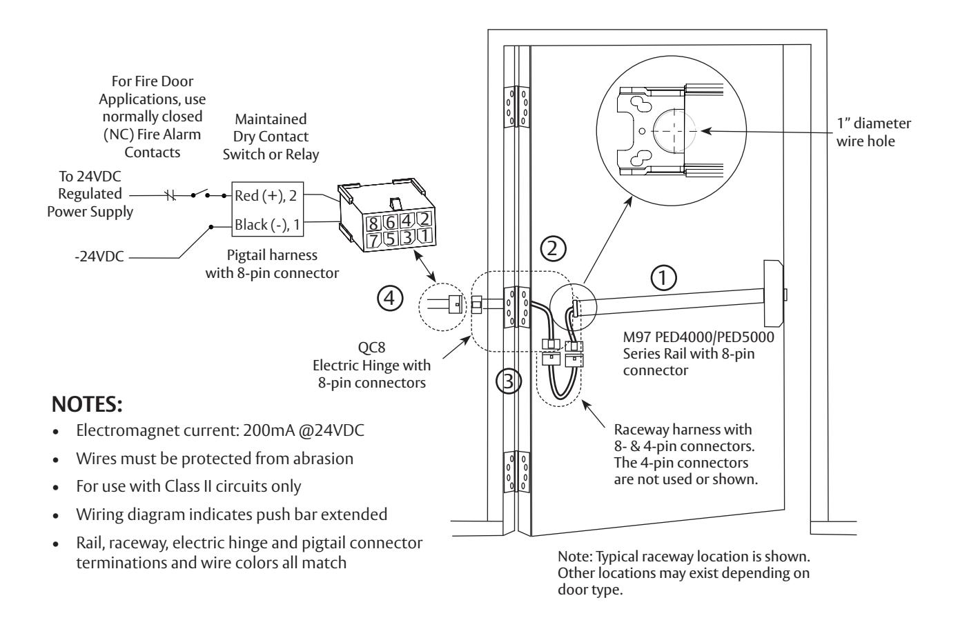
M97 prefix (electric dogging) Electromagnet current: 200mA @ 24VDC

Caution: Disconnect all input power before beginning installation to prevent electrical shock and equipment damage. All wiring must comply with applicable local electrical codes, ordinances and regulations. Installer must be a trained, experienced service person.
with optional connections
Installation Manual

4 ElectroLynx Connector System Notes
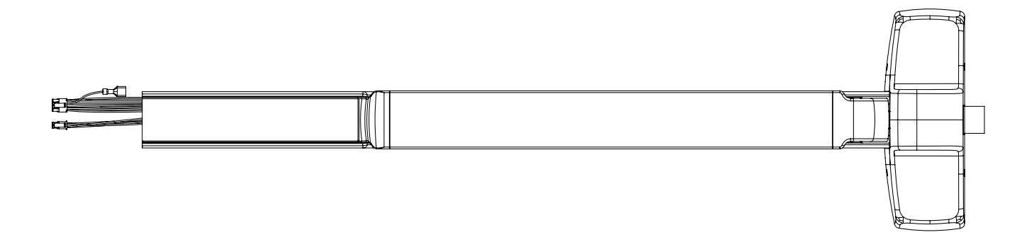
The system is designed to be installation friendly with quick connectors from the electric hinge through the door to the rail. The only wiring required is to the loose wires on the pigtail harness assembly on the frame side of the electric hinge.
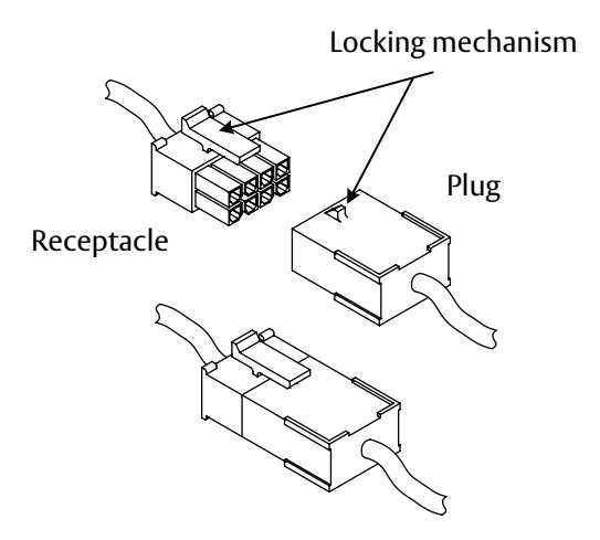
Important: The plug and receptacle connectors are designed to mate and lock together as shown in the figure. Plug the connectors into each other with the locking mechanism aligned as indicated.
Do not force connectors on any other way.
These notes apply to all of the following devices concerning the installation and wiring to the ElectroLynx Connector System
- 1. With new applications, a raceway harness with 8 and 4 pin connectors will be pre-installed inside door by ASSA ABLOY door manufacturer when specified during the ordering process. Raceway harness kits are also available for retrofit applications.
- 2. If door does not have a raceway harness with connectors, cut connectors off product, or consult factory for raceway retrofit kit.
- 3. Wiring to pigtail harness is per facility wiring requirement. The rail, raceway, electric hinge and pigtail connector terminations and wire colors all match.
with optional connections

with optional connections
Installation Manual

5 Wire Routing - continued
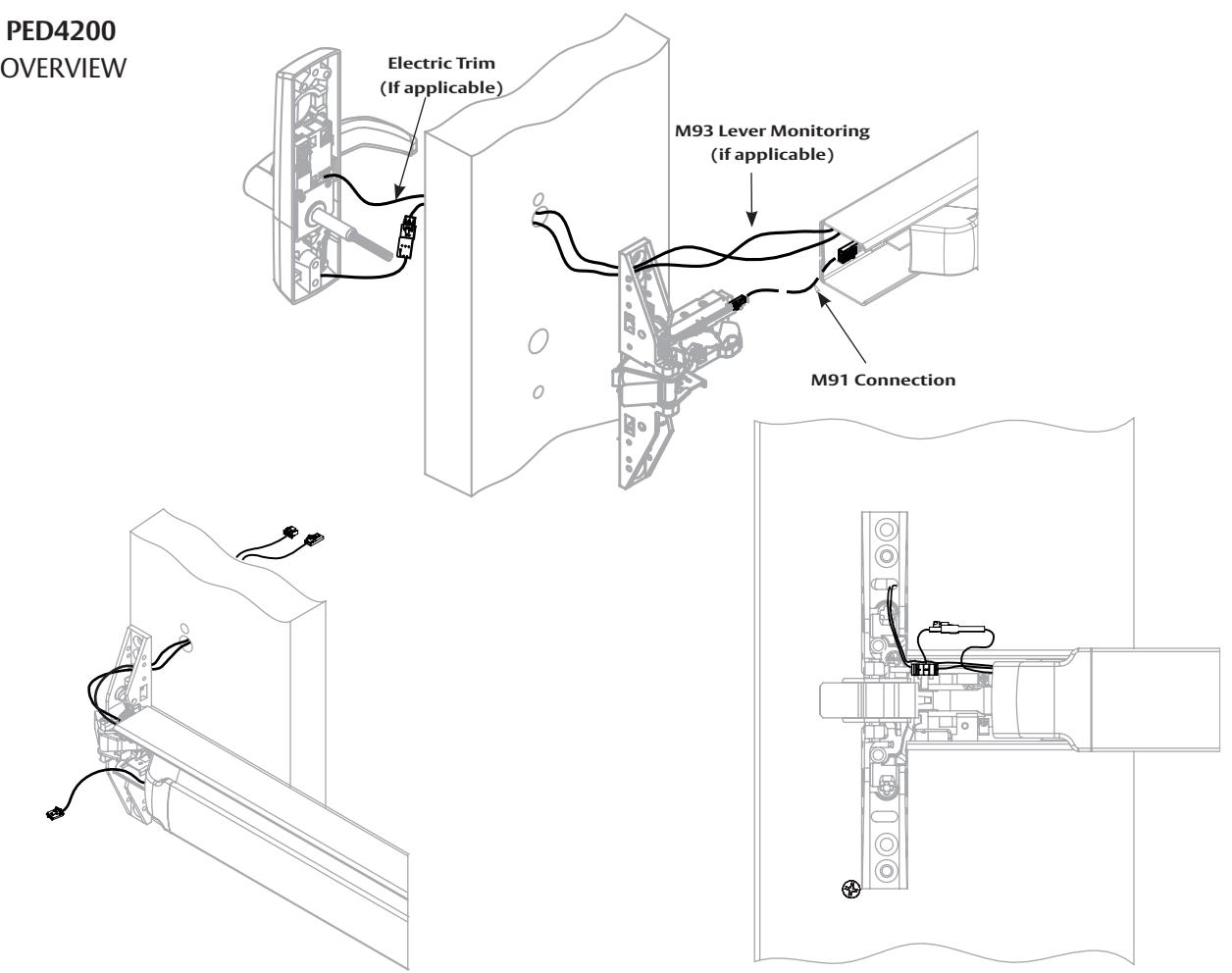
PED4800 OVERVIEW
with optional connections
Installation Manual

5 Wire Routing - continued
PED4800
Step 1. Route wires as shown and secure trim to door.
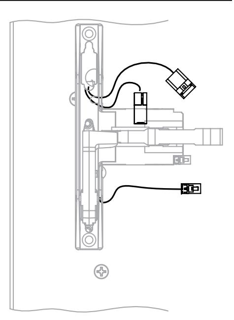
Step 2. Route wires through chassis as shown and secure chassis to door.
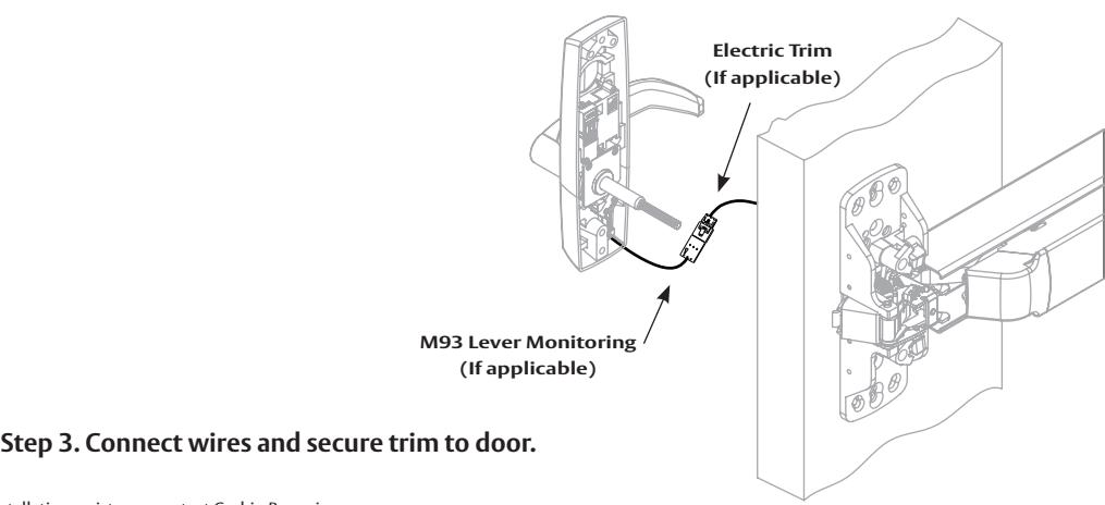
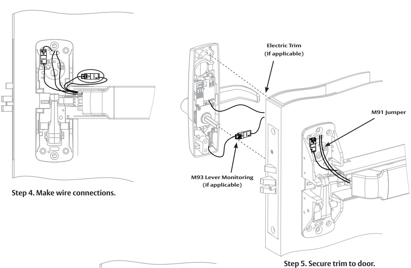
Step 3. Install rail. Step 4. Make wire connections.
Step 5. Pull back excess wire through rail. Route wires as shown. Install wire clips.
with optional connections
Installation Manual

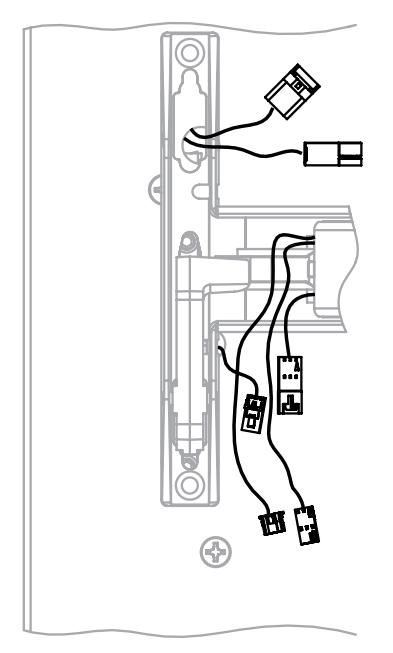
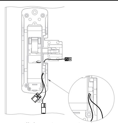
5 Wire Routing - continued
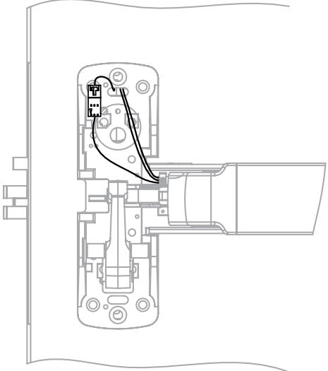
Step 2. Secure trim. Make M91 connection. Step 1. Install chassis to rail. Route wires through door as shown.
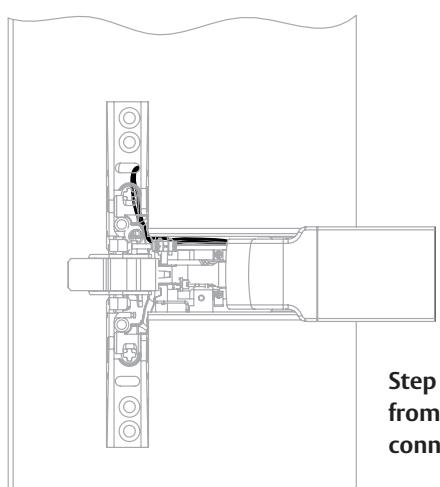
Step 3. Pull additional wire slack through rail from insert end and tuck latch bolt monitor (M91) connection into chassis.
with optional connections
Installation Manual

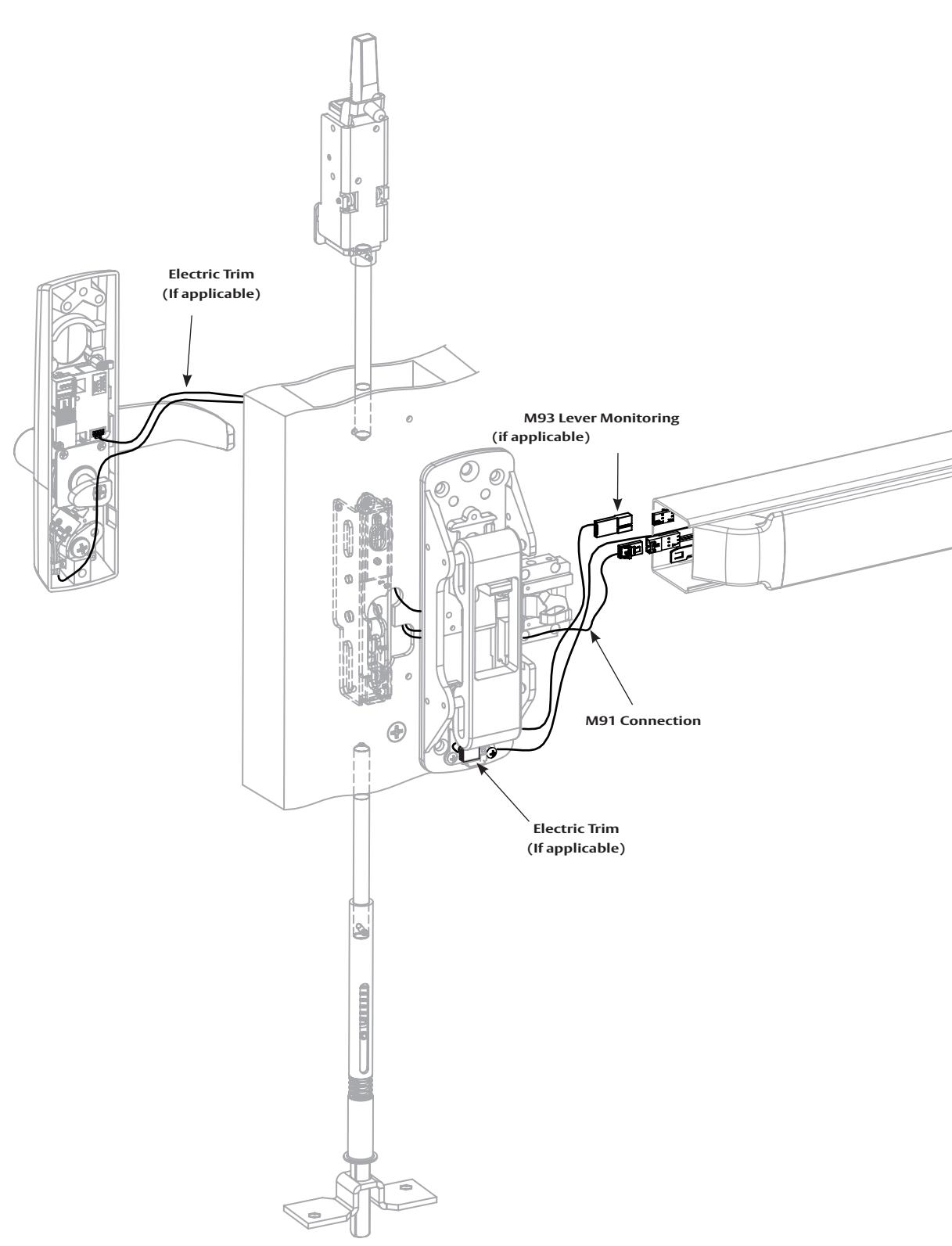
5 Wire Routing - continued
PED5800 OVERVIEW
For installation assistance contact Corbin Russwin 1-800-543-3658 • techsupport.corbinrusswin@assaabloy.com
9
with optional connections
Installation Manual

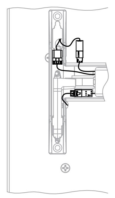
5 Wire Routing - continued
PED5800
Step 1. Route wires as shown and secure trim to door.
Step 2. Install chassis (Section 4) and route wires through chassis as shown.
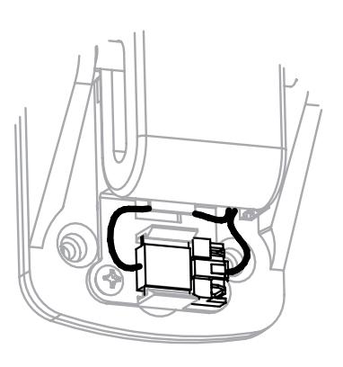
Step 3. Install rail. Step 4. Make wire connections. Step 5. Snap trim jumper to clip and route excess wire as shown.
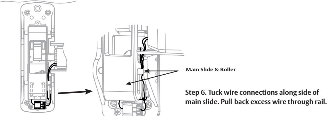
Step 6. Tuck wire connections along side of
with optional connections
Installation Manual

5 Wire Routing - continued
PED5400 OVERVIEW
with optional connections
Installation Manual

5 Wire Routing - continued
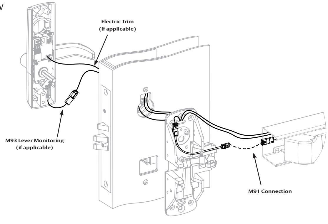
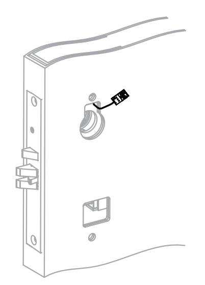
PED5400

Step 1. Install chassis and rail. Route trim wires from rail under brass lift lever as shown.
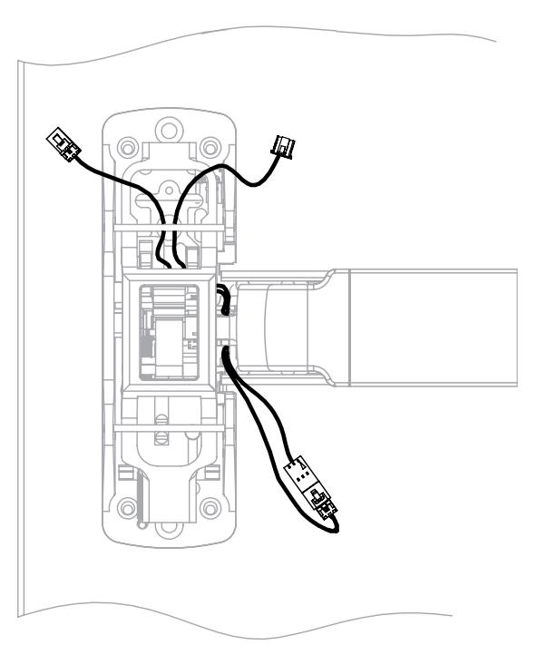
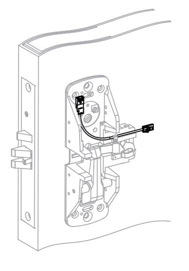
Step 2. Make M91 connection.
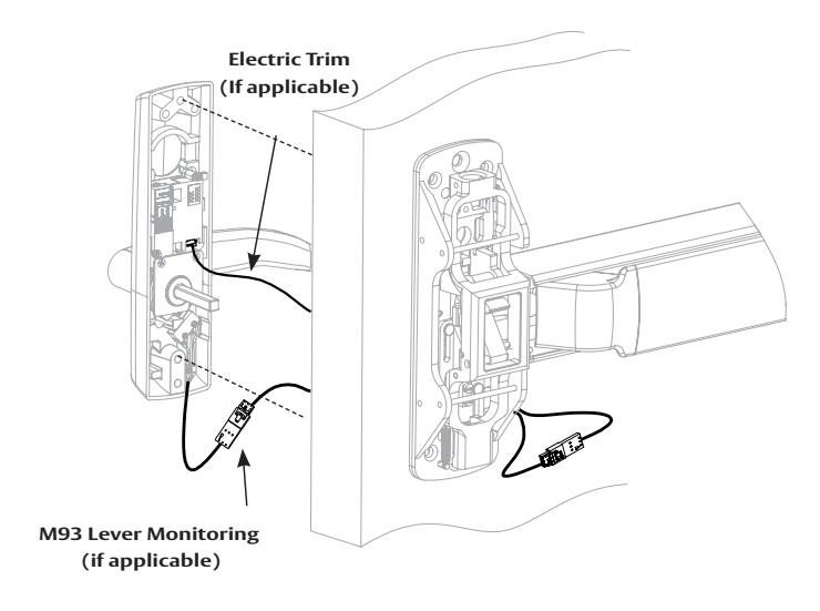
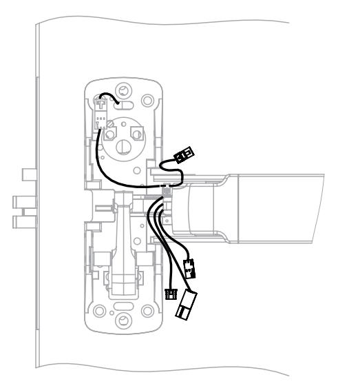
Step 3. Route trim wires through chassis and door as shown. Step 4. Make trim wire connections and secure trim to door. Pull back excess wire through rail.
with optional connections
Installation Manual

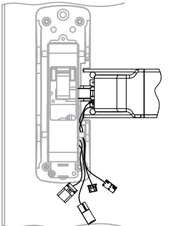
5 Wire Routing - continued
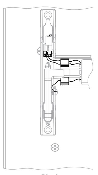
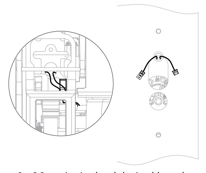
PED5200 OVERVIEW
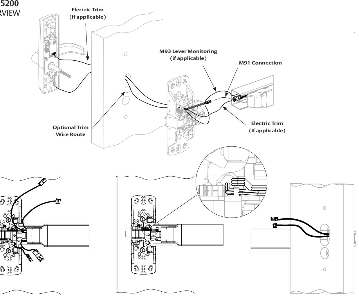
Step 1. Install chassis and rail. Step 2. Route trim wires through chassis and door as shown above.
Step 2A. Additional view
For installation assistance contact Corbin Russwin 1-800-543-3658 • techsupport.corbinrusswin@assaabloy.com
with optional connections
Installation Manual

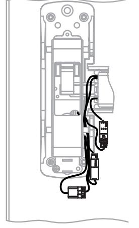
5 Wire Routing - continued
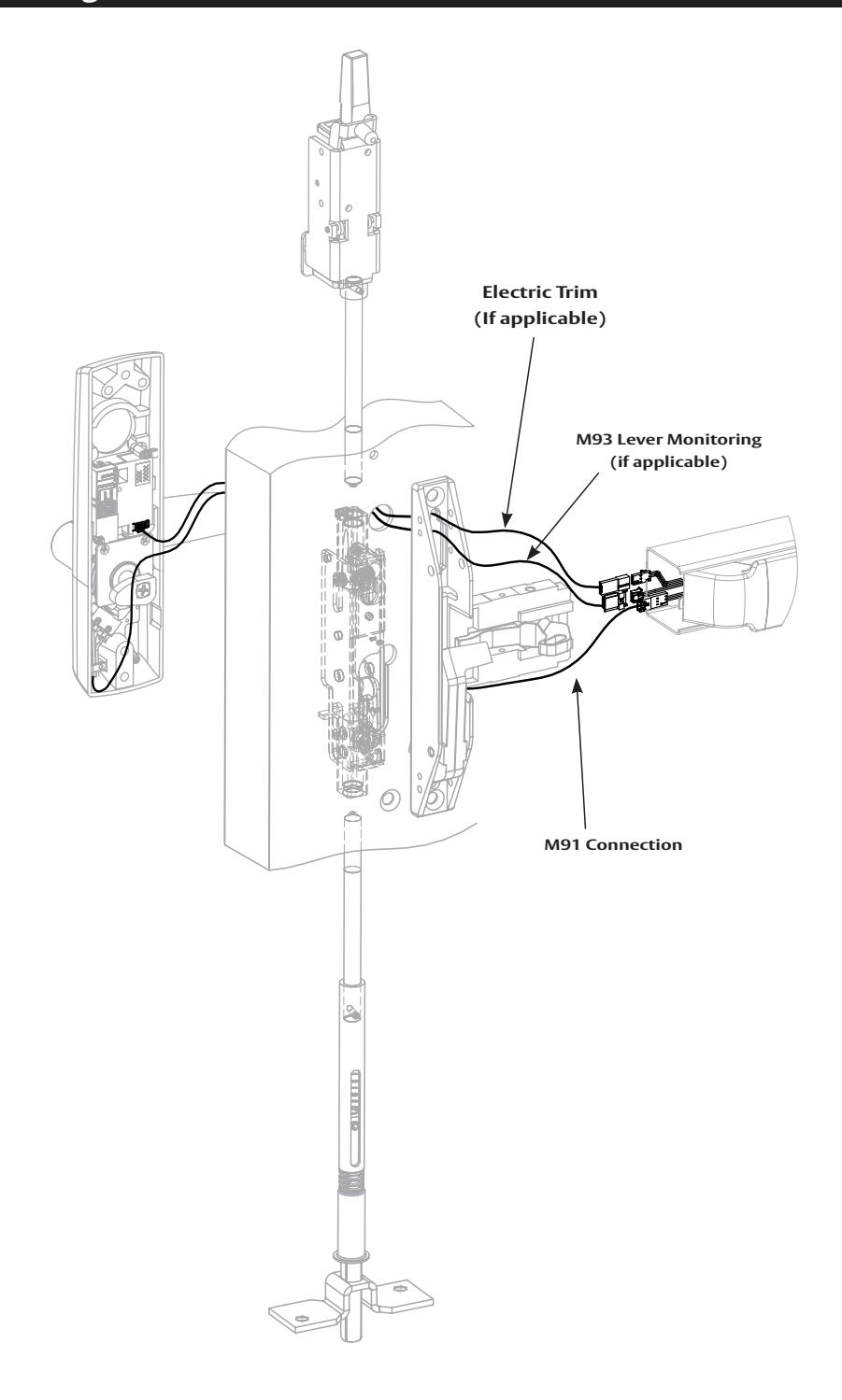
PED5600 OVERVIEW
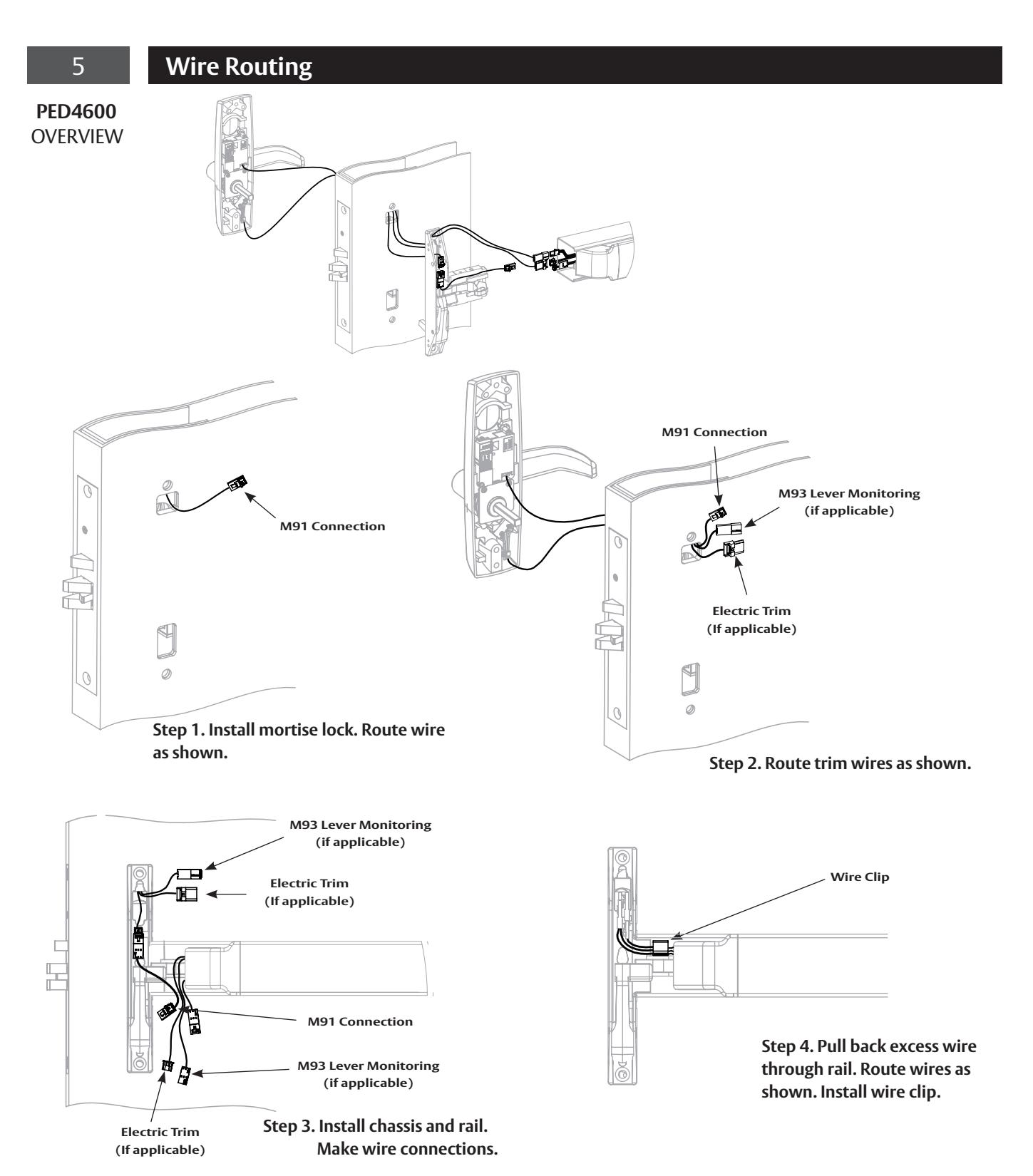
wire as shown.
Step 2. Install chassis and connect M91 jumper at chassis. Step 1. Install mortise lock. Route Step 3. Install rail to chassis.
with optional connections
Installation Manual

5 Wire Routing - continued
PED5600
Step 6. Pull back excess wire through rail.
with optional connections
Installation Manual

PE Series Installation and Wiring Overview
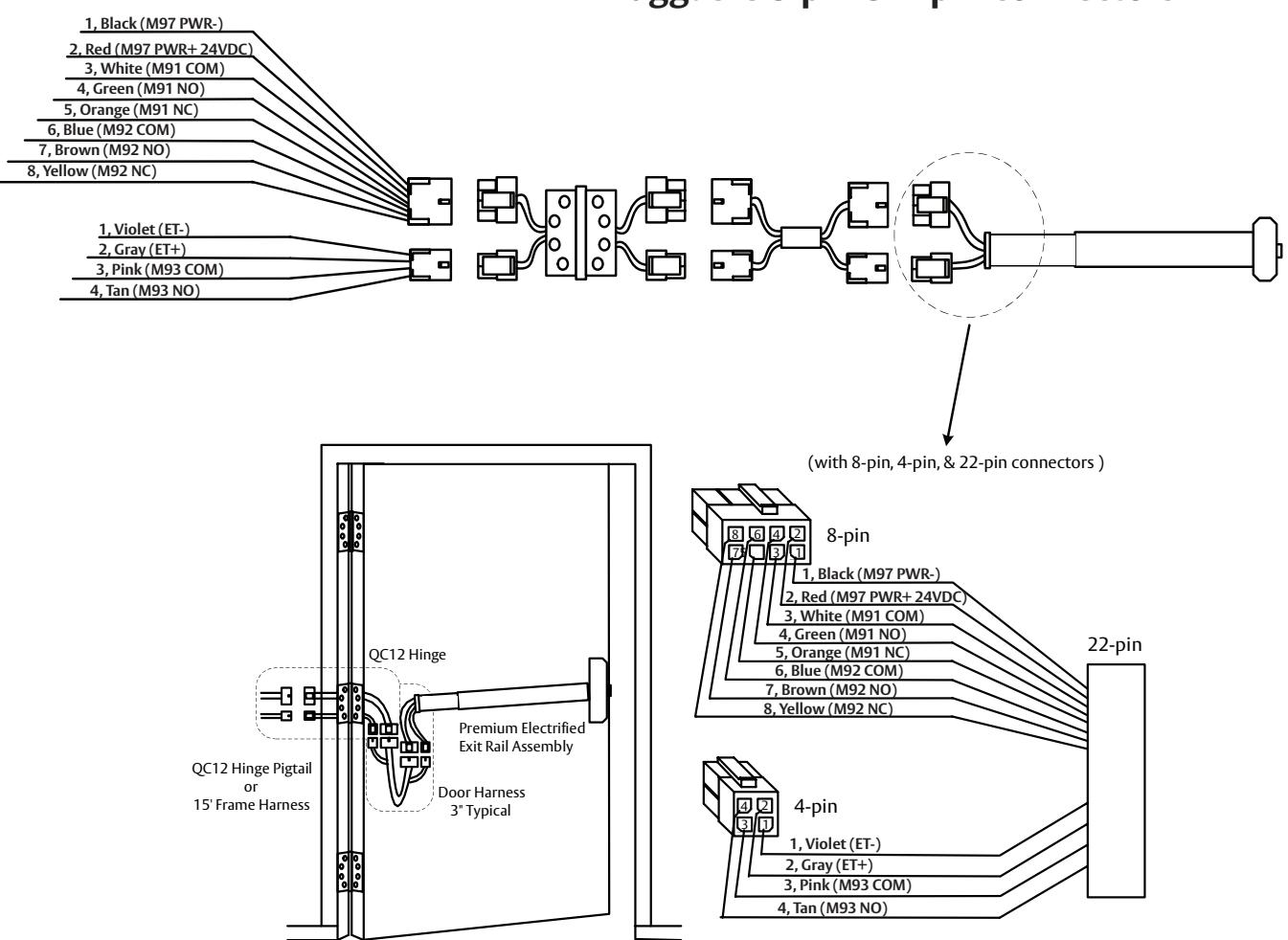
ElectroLynx System Wiring Options QC12 Hinge (12 wires) Pluggable 8-pin & 4-pin connectors
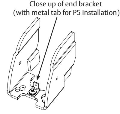
P5 connector (EGND) -Plug this into the end bracket's metal tab.
FM575 01/23
For installation assistance contact Corbin Russwin 1-800-543-3658 • techsupport.corbinrusswin@assaabloy.com
with optional connections
Installation Manual

7 M91Prefix (Latch Monitor Switch) - Exit Device to Frame Connection
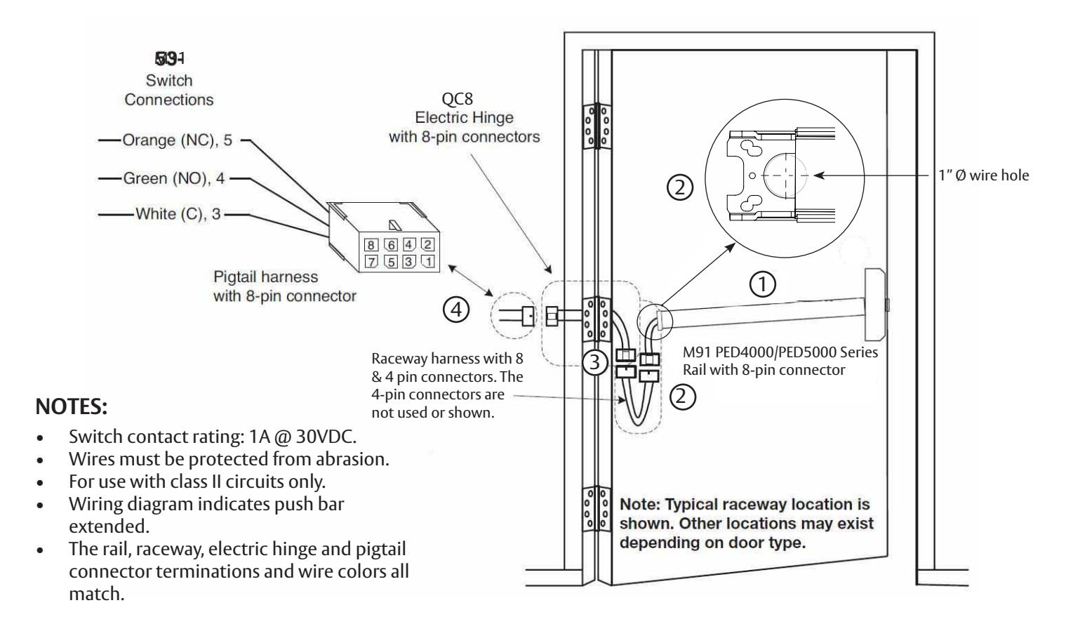
Installation Instructions:
1 Mount exit device per instruction sheet provided.
To insure trouble free operation, check that the push rail can be fully depressed. On vertical rod exit devices, check that the latch bolts do not go into hold back position until the push rail is fully depressed.
- Plug rail connector into raceway connector. Then feed through 1" hole in door. Install rail mounting bracket with two screws supplied. Install rail insert and end cap. 2
- Plug raceway connector into electric hinge connector, then feed through door prep. Mount electric hinge to door. 3
-
Go to (A) if wiring now. Go to (B) if wiring is to be done later. 4
- (A) Wire frame side wires to wires on pigtail harness as required using connectors allowed by local code. Plug pigtail harness connector into electric hinge connector. Feed harnesses through frame prep and mount electric hinge.
- (B) Plug pigtail harness connector into electric hinge connector. Feed harnesses through frame prep and mount electric hinge.
with optional connections
Installation Manual

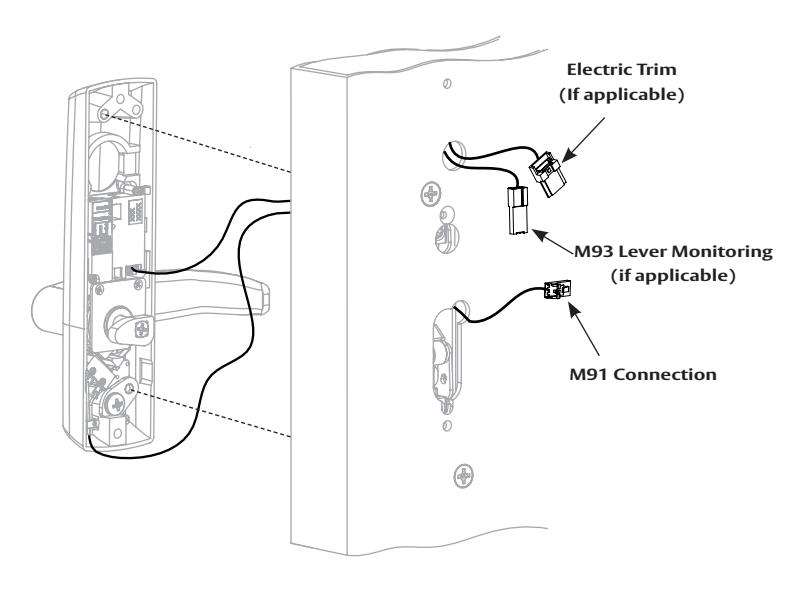
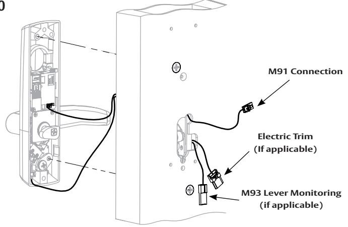
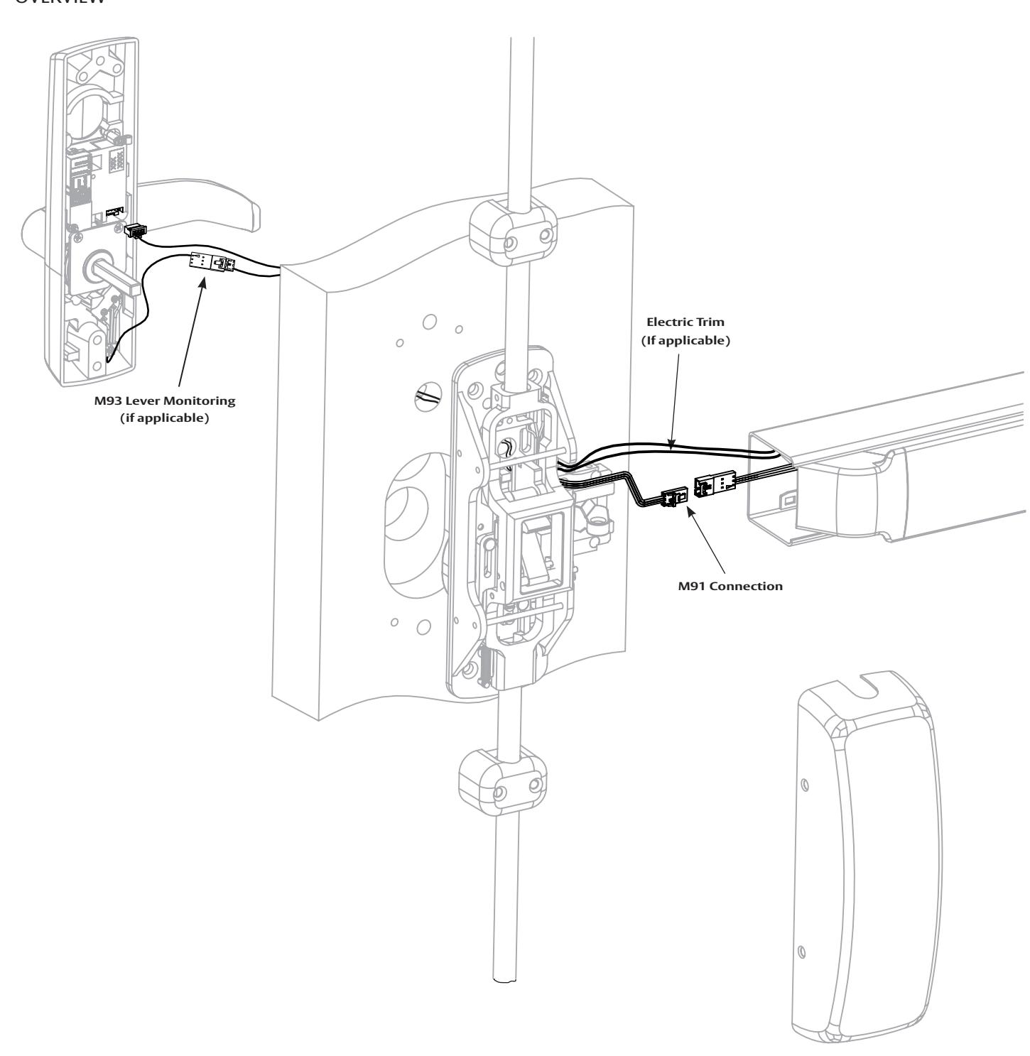
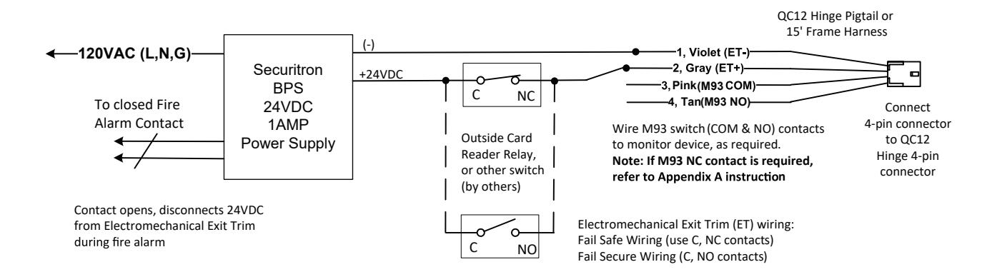
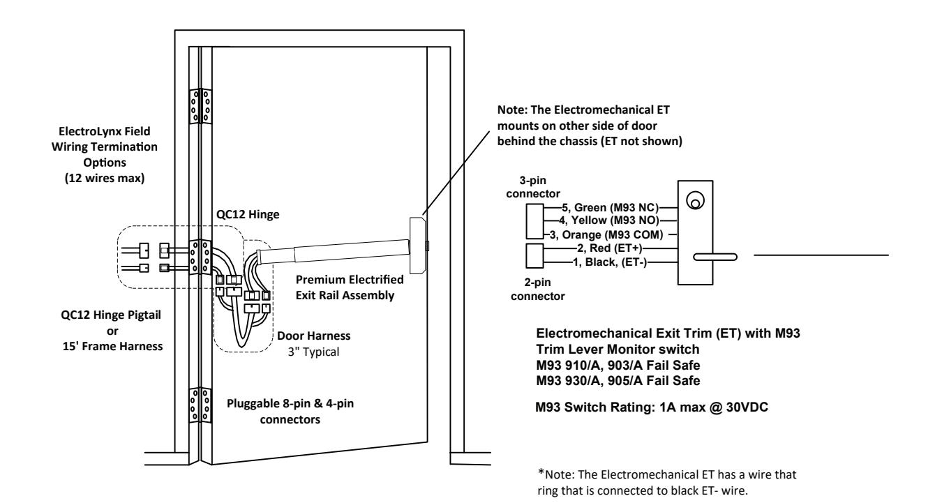
8 M93 Prefix (Trim Monitor Switch) - Exit Device to Frame Connection
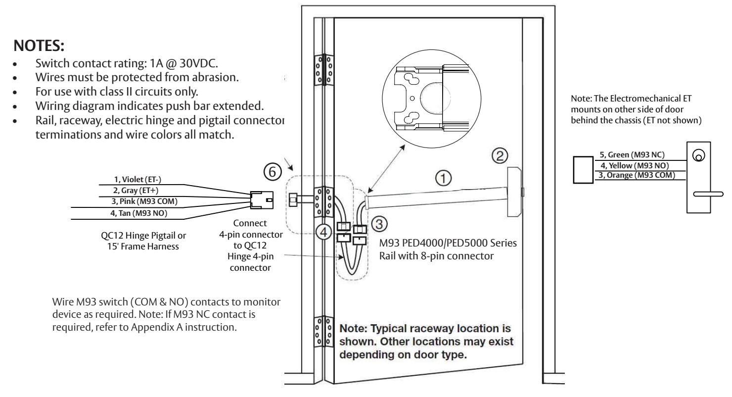
Installation Instructions:
- Mount exit device per instruction sheet provided. 1
- 2. From outside of door, route Electromechanical ET wire harness through chassis and door, then plug 3-pin connector into mating rail harness 3-pin connector.
- 3. Ensure wires are tucked in to avoid pinching wires by push bar or chassis mechanism.
- Plug rail connector into raceway connector. Then feed through 1" hole in door. Install rail mounting bracket with two screws supplied. Install rail insert and end cap. 4
- Plug raceway connector into electric hinge connector, then feed through door prep. Mount electric hinge to door. 5
-
Go to (A) if wiring now. Go to (B) if wiring is to be done later: 6
- (A) Wire frame side wires to wires on pigtail harness as required using connectors allowed by local code. Plug pigtail harness connector into electric hinge connector. Feed harnesses through frame prep and mount electric hinge.
- (B) Plug pigtail harness connector into electric hinge connector. Feed harnesses through frame prep and mount electric hinge.
- 7. Test lock M93 trim lever monitor switch monitors lever movement. Switch changes state when lever is rotated.
with optional connections
Installation Manual

9 M92 Prefix Push Bar (Signal Switch) - Exit Device to Frame Connection
M92 PE Series (Signal Switch) Installation and Wiring
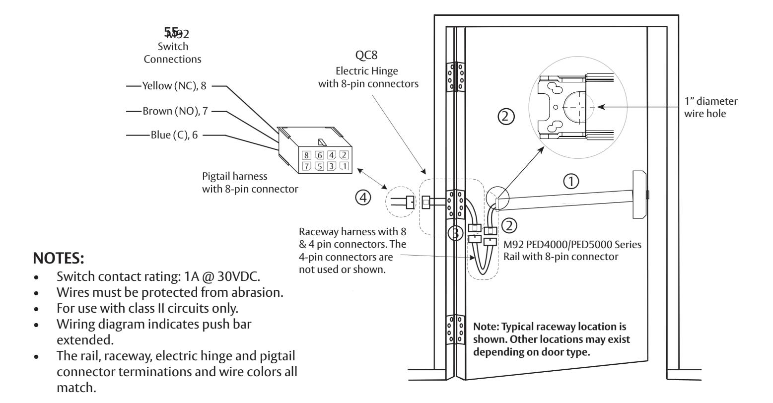
Installation Instructions:
1 Mount exit device per instruction sheet provided.
To insure trouble free operation, check that the push rail can be fully depressed. On vertical rod exit devices, check that the latch bolts do not go into hold back position until the push rail is fully depressed.
- Plug rail connector into raceway connector. Then feed through 1" hole in door. Install rail mounting bracket with two screws supplied. Install rail insert and end cap. 2
- Plug raceway connector into electric hinge connector, then feed through door prep. Mount electric hinge to door. 3
-
Go to (A) if wiring now. Go to (B) if wiring is to be done later. 4
- (A) Wire frame side wires to wires on pigtail harness as required using connectors allowed by local code. Plug pigtail harness connector into electric hinge connector. Feed harnesses through frame prep and mount electric hinge.
- (B) Plug pigtail harness connector into electric hinge connector. Feed harnesses through frame prep and mount electric hinge.
with optional connections
Installation Manual

10 M97Prefix Electric Dogging - Exit Device to Frame Connection
Installation Instructions:
1 Mount exit device per instruction sheet provided.
To insure trouble free operation, check that the push rail can be fully depressed. On vertical rod exit devices, check that the latch bolts do not go into hold back position until the push rail is fully depressed.
- Plug rail connector into raceway connector. Then feed through 1" hole in door. Install rail mounting bracket with two screws supplied. Install rail insert and end cap. 2
- Plug raceway connector into electric hinge connector, then feed through door prep. Mount electric hinge to door. 3
-
Go to (A) if wiring now. Go to (B) if wiring is to be done later. 4
- (A) Wire frame side wires to wires on pigtail harness as required using connectors allowed by local code. Plug pigtail harness connector into electric hinge connector. Feed harnesses through frame prep and mount electric hinge.
- (B) Plug pigtail harness connector into electric hinge connector. Feed harnesses through frame prep and mount electric hinge.
with optional connections
Installation Manual

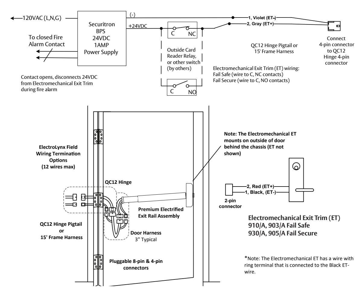
11 910/A, 930/A, 903/A, 905/A (Electromechanical Exit Trim) - Exit Device to Frame Connection
- 1. Mount exit device per instruction sheet provided.
- 2. From outside of door, route Electromechanical ET wire harness through chassis, then plug 2-pin connector into mating rail harness 2-pin connector. Ensure wires are tucked in to avoid pinching wires by push bar or chassis mechanism.
- 3. Wire to the QC12 Hinge pigtail harness 4-pin connector.
- 4. Ensure proper voltage is being applied to pigtail harness.
- 5. Plug pigtail harness 4-pin connector into QC12 hinge 4-pin connector.

Caution: The DC voltage applied must not exceed 30VDC. If the applied voltage exceeds 30VDC, the electromechincal trim motor may be damaged.
6. Test lock – Fail Secure unlocks with 24VDC power applied. Fail Safe locks with 24VDC power applied.
with optional connections
Installation Manual

11 M93, 910/A, 930/A, 903/A, 905/A (Electromechanical Exit Trim), continued
with optional connections
Installation Manual

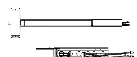
12 Appendix A: Harness Wiring Reconfiguration
Premium Electrical Exits (NO PCBA) Rail to QC12 Hinge Side Harness
22-pin connector to 8 & 4-pin ELynx connectors
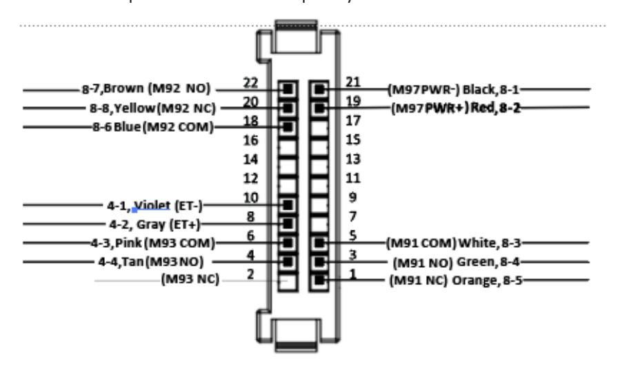
12 + 1 = 13 total wiring selections
Premium Electrical Exits (NO PCBA) ElectroLynx QC12 Factory Default Ship Configuration
| 22-21 | M97 PWR- | Black | 8-1 |
|---|---|---|---|
| 22-19 | M97 PWR+ (24VDC) | Red | 8-2 |
| 22-5 | м91 СОМ | White | 8-3 |
| 22-3 | M91 NO | Green | 8-4 |
| 22-1 | M91 NC | Orange | 8-5 |
| 22-18 | М92 СОМ | Blue | 8-6 |
| 22-22 | M92 NO | Brown | 8-7 |
| 22-20 | M92 NC | Yellow | 8-8 |
| 22-10 | ET- | Violet | 4-1 |
| 22-8 | ET+ | Gray | 4-2 |
| 22-6 | м93 сом | Pink | 4-3 |
| 22-4 | M93 NO | Tan | 4-4 |
| 22-2 | M93 NC | No wire |
LEGEND - Premium Exits Electrical Options, NO PCBA
M91 Latch Monitor Switch (Form C) in Chassis, remote monitor, etc.
M92 Push Bar Switch (Form C) – REX, de-energize external magnet, remote monitor, etc.
M97 Electric Dogging (magnet in rail) - manually press push bar to dog rail when powered
ET Electrified Exit Trim (Ecoflex motor 10 to 30VDC)
M93 ET Lever Monitor Switch (Form C)
The factory ships the rail to hinge side harness with 12 default wires terminated from the 22-pin connector to 8-pin & 4-pin connectors.
There are a total of 13 wiring choices (with 1 additional wiring choice):
M93 N.C.
Wire reconfiguration:
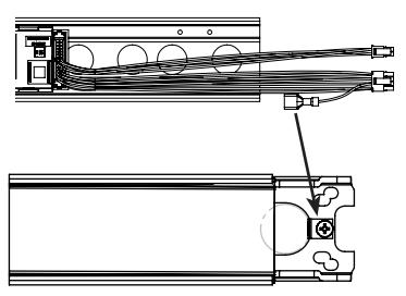
- 1. Remove exit device end cap.
- 2. Slide the metal insert cover off of rail.
- 3. Unplug the harness 22-pin connector from mating rail harness 22-pin connector.
with optional connections
Installation Manual

13 Appendix A: Harness Wiring Reconfiguration, continued
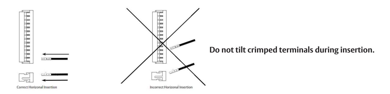
Follow correct Horizontal Insertion view when inserting crimped terminal/wire into socket (26-pin connector), as shown below. For re-pinning, please contact technical service at 1-800-727-5477.
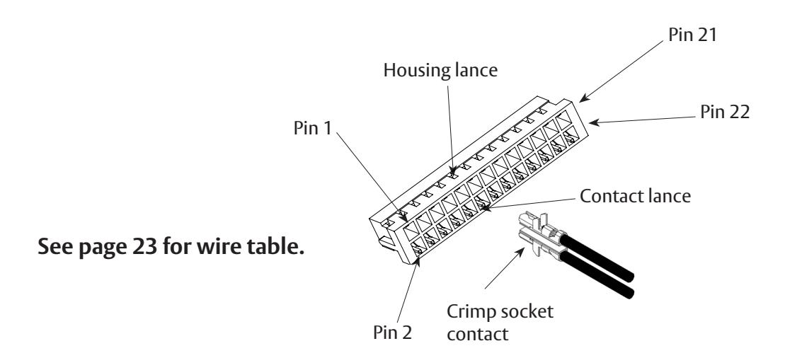
If the M93 NC (22-2) contact is required instead of M93 NO (22-4, Tan wire):
Remove crimped contact/tan wire assembly from 22 pin connector position 4 (22-4), using pointed tool to lift up plastic locking housing lance on connector, then slowly and carefully remove the contact/tan wire assembly from connector by hand.
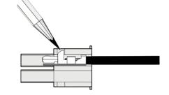
Insert crimped contact/wire assembly into new connector position 22-2 (M93 NC). Be sure to follow correct Horizontal Insertion view when inserting crimped terminal/wire into socket (22-pin connector), as shown.
Plug in 22-pin mating harness connectors, re-install rail metal insert cover, complete hinge side facility wiring, then re-install end cap.
with optional connections

with optional connections

with optional connections


Corbin Russwin 225 Episcopal Road Berlin, CT 06037 Phone: 800-543-3658 Fax: 800-447-6714 corbinrusswin.com
Copyright © 2023 ASSA ABLOY Access and Egress Hardware Group, Inc. All rights reserved. Reproduction in whole or in part without the express written permission of ASSA ABLOY Access and Egress Hardware Group, Inc. is prohibited.
Patent pending and/or patent - www.assaabloydss.com/patents. HID, iCLASS, and Edge are trademarks or registered trademarks of HID Global Corporation.