Corbin Russwin EcoFlex Mortise Locks Installation Instructions
Open the original PDF document
View PDF

FM405 04/15
Attention Installer
Please read these instructions carefully to prevent missing important steps.
Please Note: Improper installations may result in damage to the lock and void the factory warranty.
Important: The accuracy of the door preparation is critical for proper functioning and security of this lock.
Misalignment can cause premature wear and a lessening of security.
For Technical Assistance call Corbin Russwin at 1-800-810-WIRE (9473)

Table of Contents
| 1) Warning 2 | |
|---|---|
| 2) General Description 3 | |
| 3) Specifications / Features | 3 |
|
4) Product Illustration
4 |
|
| 5) Installation Instructions 5 | |
| 6) Wiring Diagrams14 | |
|
7) Operational Checks
15 |

2) General Description
The NAC- mortise lock provides increased security over typical electrified mortise locks with dead bolt, dead bolt monitoring, request to exit monitoring, and door status monitoring built into a single lock. This lock can also be specified with factory installed and tested end-of-line resistors monitoring the request to exit and door position outputs.
The high security monitoring options of our industry-leading Integrated Wiegand locks are now available in a mortise lock that can be used as a stand-alone electrified lock or in conjunction with a wall reader.
Every NAC lock is shipped with door position and request to exit monitoring installed. NAC locks ordered with deadbolt are supplied with deadbolt monitoring.
3) Specifications / Features
If your lock is configured with End of Line Resistors, reference instruction sheet FM406 for the wiring of RX & DPS outputs.
- Latch Stainless steel, 3⁄4" projection
- Deadbolt Stainless steel, 1" projection
- Guardbolt Stainless steel, non-handed
- Handed Easily field reversible without opening case
- Case 12 gauge heavy duty wrought steel
- Fail safe or fail secure operation (specified when ordering or easily field-configurable)
- Operates from 12-24VDC
- UL and CUL listed for use on Fire Doors
Electrical Specifications
12/24VDC System
- Actuator draw = .015 Amp continuous
- Maximum 2 locks per 1 Amp power supply (1/2 Amp peak current draw)
Example:
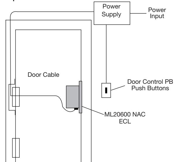
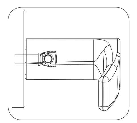
ElectroLynx® Connector System Notes
The system is designed to be installation-friendly with connectors from the electric hinge through the door to the lock. External electrical connections are made to a harness that extends from the frame.
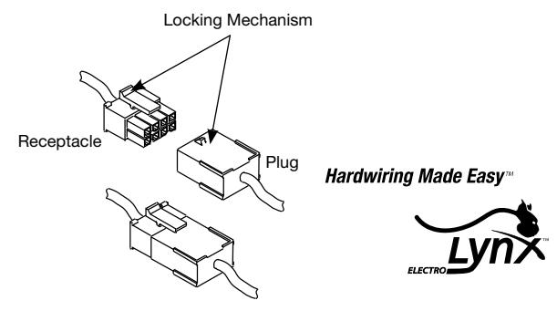
ElectroLynx®is a registered trademark of ASSA ABLOY, Inc.
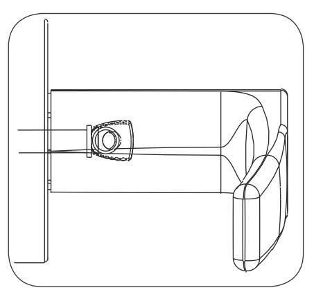
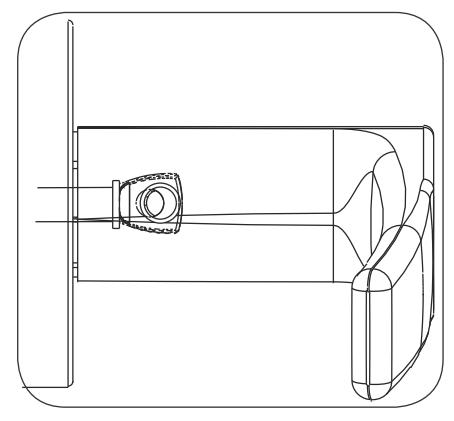
IMPORTANT:
The plug and receptacle connectors are designed to mate and lock together as shown in the illustration. Plug the connectors into each other with the locking mechanism aligned as indicated.
Copyright © 2015 Corbin Russwin, Inc., an ASSA ABLOY Group company. All rights reserved. Reproduction in whole or in part without the express written permission of Corbin Russwin, Inc. is prohibited.

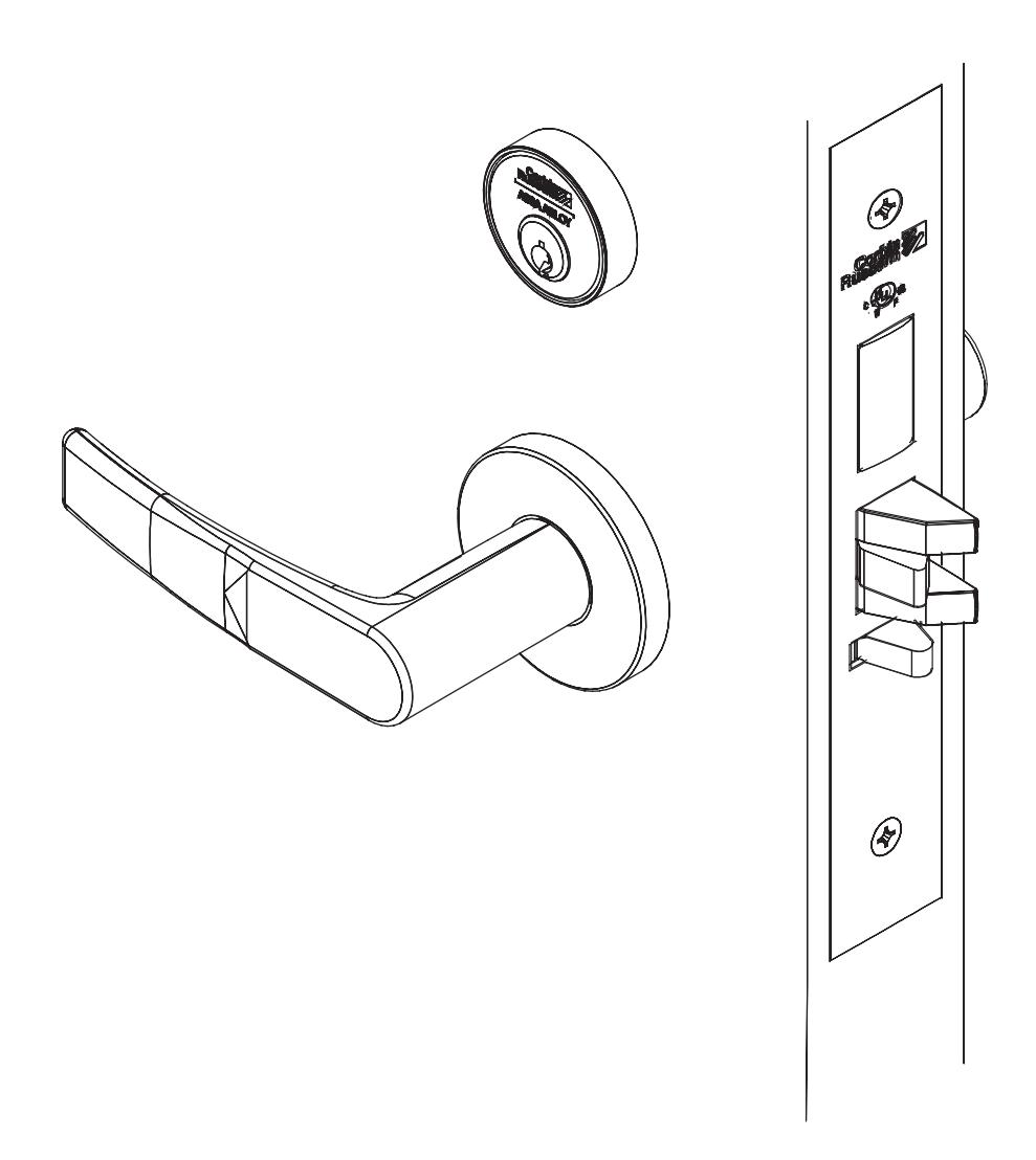
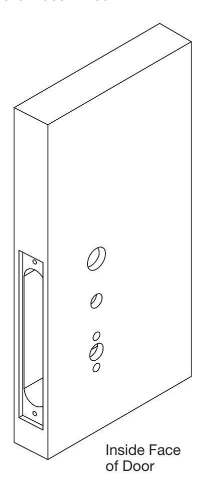
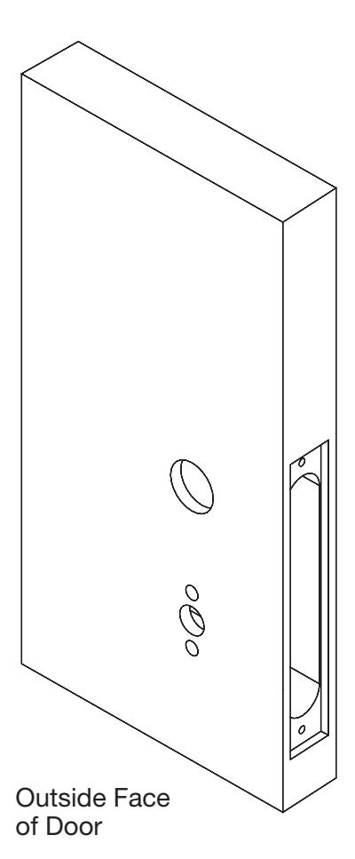
4) Product Illustration
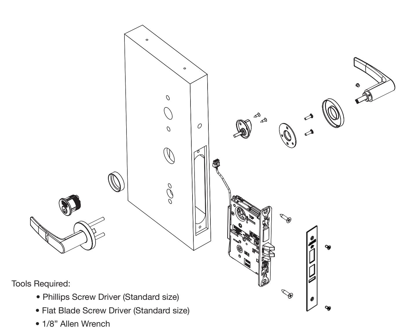

5) Installation Instructions
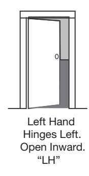
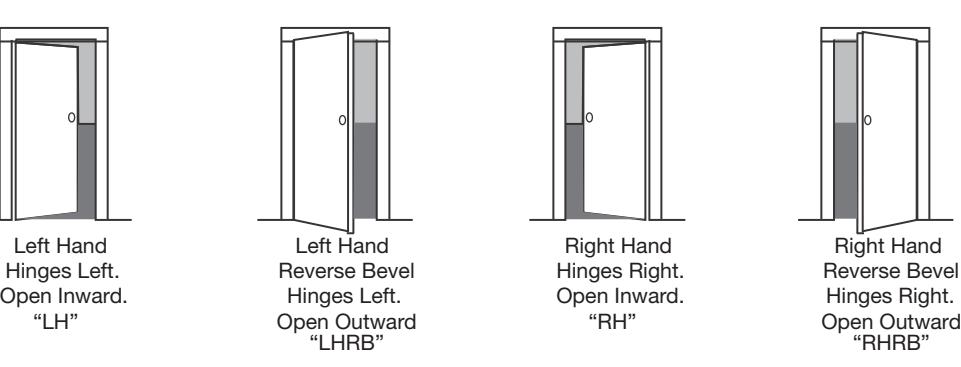
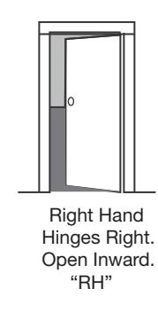
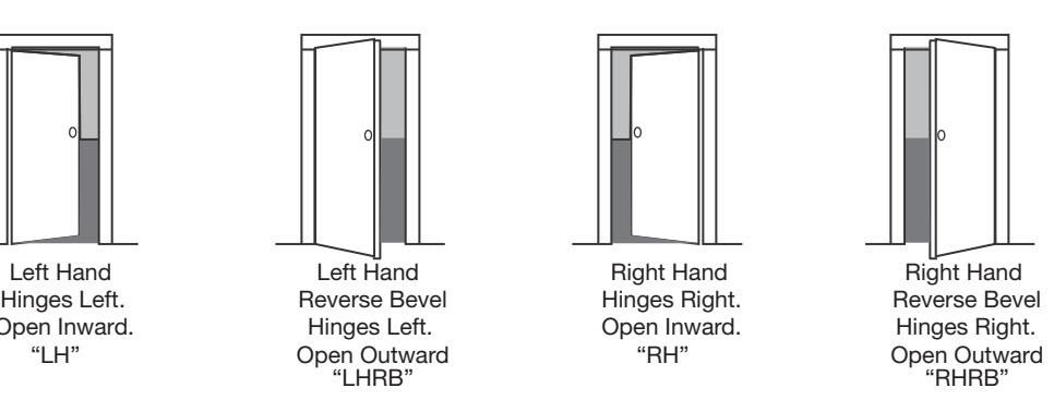
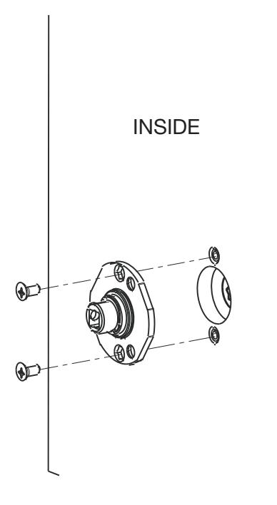
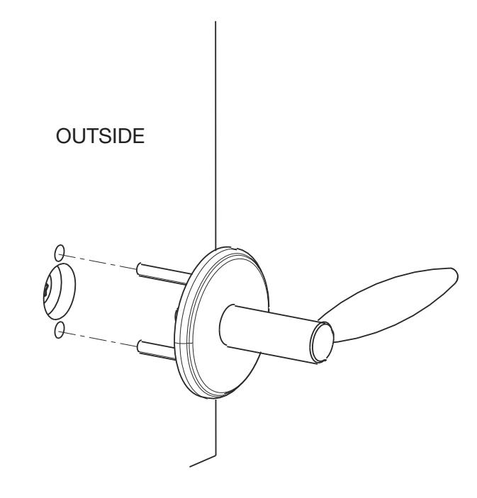
1. Verify Hand and Bevel of door. Illustrations shown are as viewed from the outside or secure side of opening.
2. Prep door according to supplied door marker. For door manufacturer templates, visit www.corbinrusswin.com.

5) Installation Instructions (Continued)
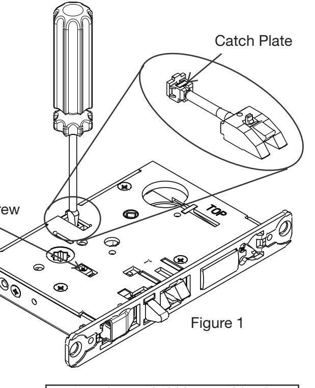
3. Handing of Lock Body
- 1. Move the red locking screw to side of lock body being locked (Fig. 1)
- 2. Push in latch then depress catch plate with screw driver (Fig. 1)
- 3. Pull latch out of lock body and turn latch over (Fig. 2)
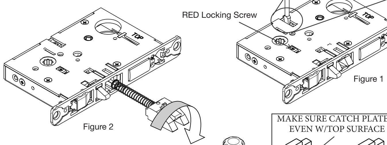
Step 4) Push in latch while holding screw driver behind latch tail (Fig. 3)
Note: Push in latch until catch plate is
Step 5) Rotate lock front to match
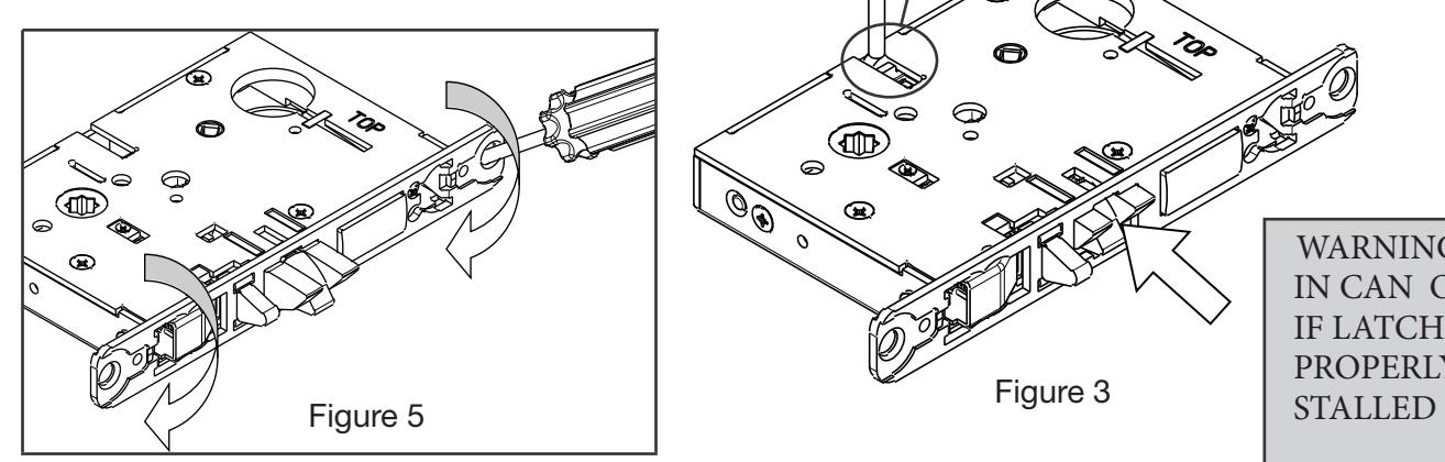
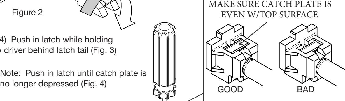
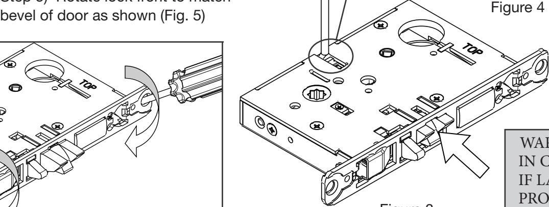
WARNING: LOCK-IN CAN OCCUR IF LATCH IS NOT PROPERLY IN-

5) Installation Instructions (Continued)
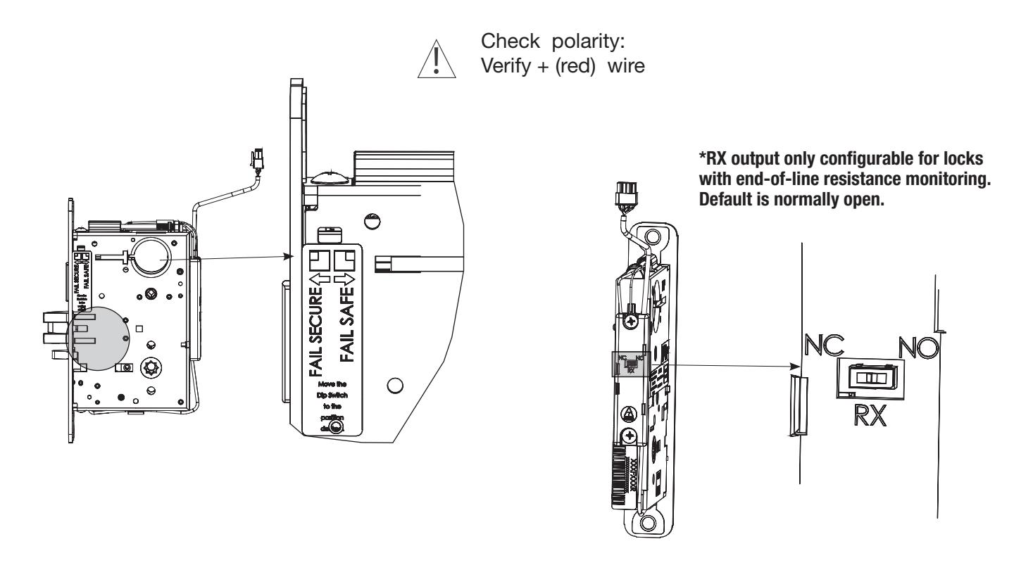
4. Configuring the Fail Safe/Fail Secure and RX* DIP switch settings:
Please note that the lock must be cycled once in order for setting changes to take effect.
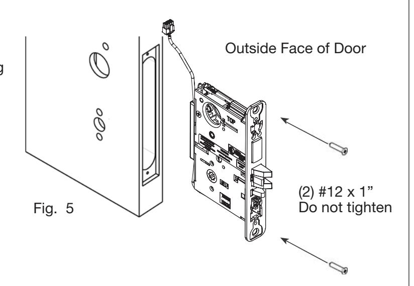
5. Install Lock Body into Door:
- a. Plug mortise lock harness into ElectroLynx® harness in door (Fig. 5). Important: Door must remain open during installation. Use door stop.
- b. Install, but do not tighten two #12 x 1" combination screws through lock body (Fig. 5).

5) Installation Instructions (Continued)
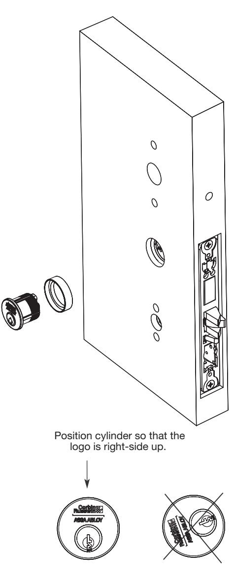
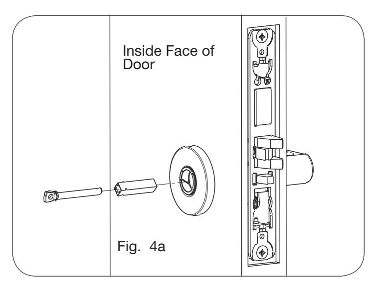
6. Install Cylinder:
- a. Thread cylinder into lock body (Fig. 6a). Note: Make sure cylinder is oriented correctly (Fig. 6a1).
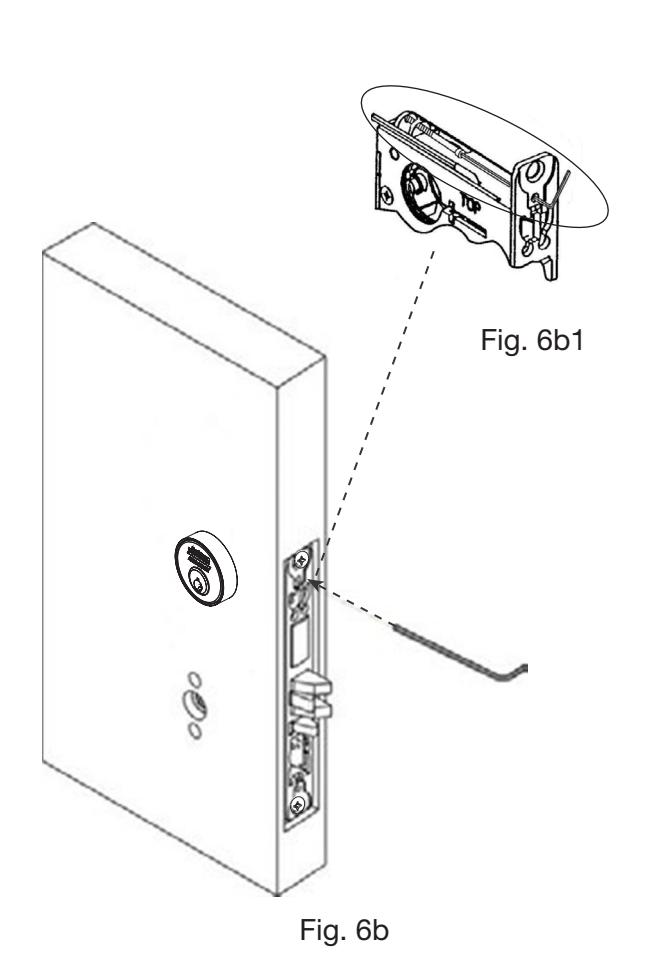
- b. Tighten cylinder clamp using 7/64" allen wrench (provided) (Fig. 6b).
- c. Turn the key to make sure that lock functions correctly (latch, deadbolt, and key).


5) Installation Instructions (Continued)
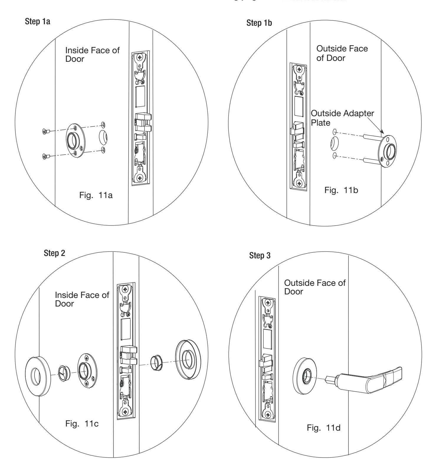
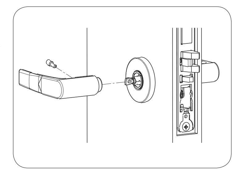
7a. Install Standard Lever Trim. Refer to 7b on following pages for Trim:

5) Installation Instructions (Continued)
Step 4
Step 5
Align adjustment bolt with threaded hole in lever
Adjustment bolt needs to be threaded in farther.
Adjustment bolt needs to be unthreaded.
Adjustment bolt fully aligned.
Step 6
Notes:
- Unthread adjustment bolt approximately four turns for a good starting point (After being fully tightened).
- Make sure O/S lever is fully inserted into adapter plate before aligning adjustment bolt.

5) Installation Instructions (Continued)
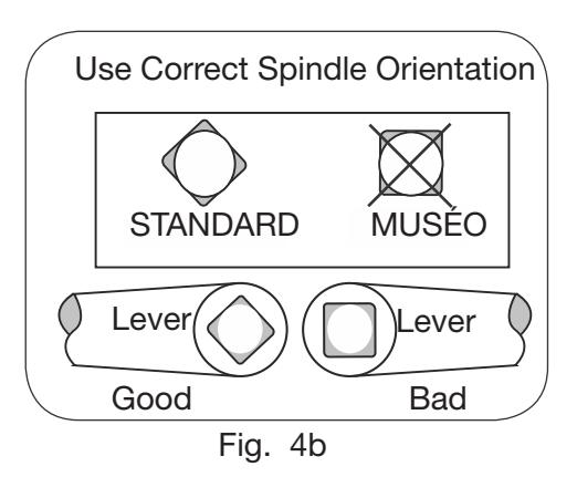
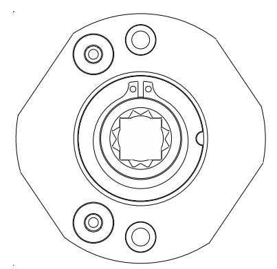
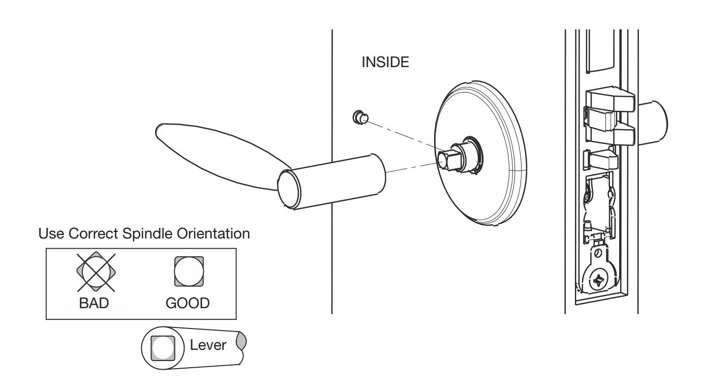
7b. Install MUSEO Trim:
1.)
Thread adapter plate hub into lever and fully tighten
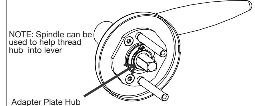
Align adapter plate hub with square hole in lever; keeping hub as tight as possible
2.)

5) Installation Instructions (Continued)
3.) Set screw in hub faces away from door edge.
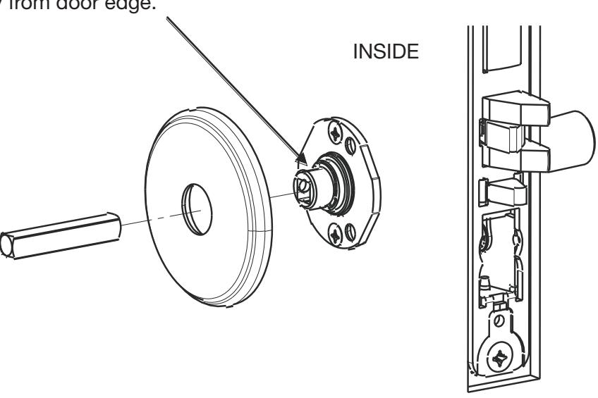
4.)

5) Installation Instructions (Continued)
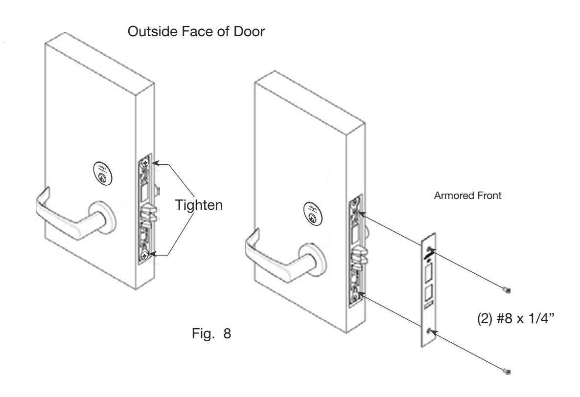
8. Install Armored Front:
- a. Tighten (2) screws through lock body.
- b. Attach armored front with two #8 x ¼" screws (Fig. 8).

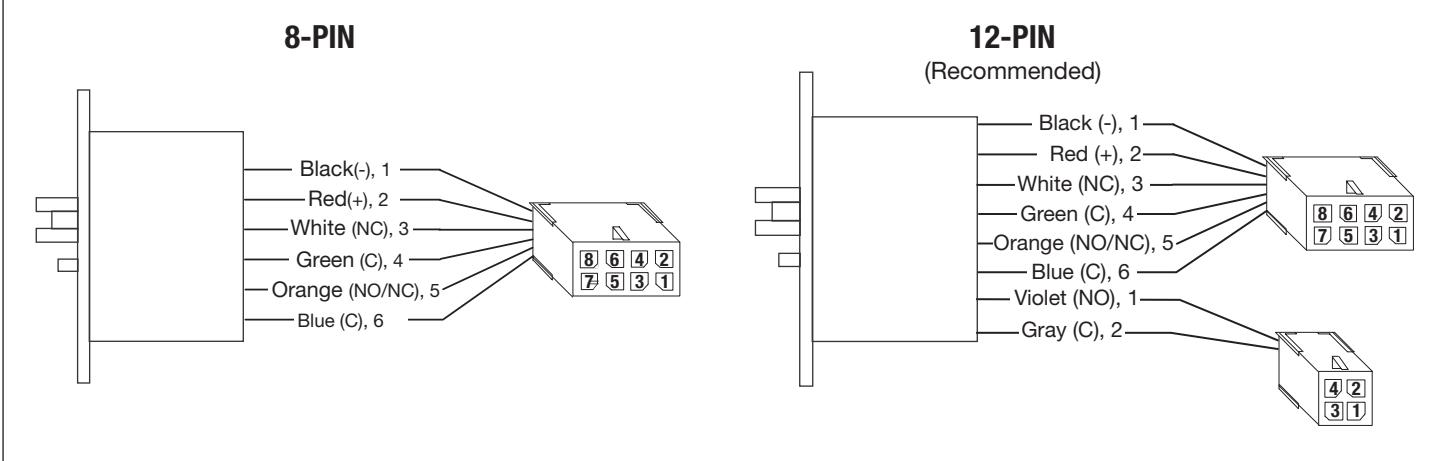
6) Wiring Diagrams
Lock Schematics
Check polarity: Verify + (red) wire
| Connector | 8-PIN MOLEX | 4-PIN MOLEX | ||||||||||
|---|---|---|---|---|---|---|---|---|---|---|---|---|
| Circuit | 1 | 2 | 3 | 4 | 5 | 6 | 7 | 8 | 1 | 2 | 3 | 4 |
| Connection | 12/24VDC Lock Input |
Door Position
Request to Exit |
Empty | Empty | Deadbolt Monitoring | Empty | ||||||
| Wire Color | Black | Red | White Green | Orange | Blue | Violet | Gray | |||||
| Description | NEG | POS | NC | COM | NO/NC | COM | NO | COM | ||||
If your lock is configured with End of Line Resistors, reference instruction sheet FM406 for the wiring of RX & DPS outputs.

7) Mechanical Operational Check
For mortise locks with cylinders:
- a. Insert key into cylinder and rotate: There should be no friction against lock case, wire harness or any other obstructions.
- b. The key will retract the latch: Key should rotate freely.
- c. Inside lever: Ensure it retracts the latch.
- d. Close door: Ensure latch fully extends and does not bind.
- e. Ensure that dead bolt can be projected and retracted by key and inside turn (if present).
8) Electrical Operational Check
Lock/UnLock Check:
- a. Turn power ON.
- b. Send unlock signal from control panel.
- c. Verify lock unlocks and re-locks at desired intervals.
Switch Signal Check:
- d. Monitor switch signals at control panel and verify each switch activates correctly based on chosen wiring configuration (NO/NC).
- e. If end-of-line resistors are present on the RX (request-to-exit) and door status outputs, verify correct signaling by referencing instruction sheet FM406.
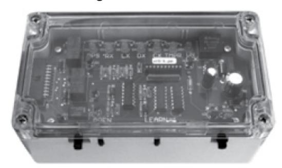
The ASSA ABLOY Wiegand Test Unit verifies your installation in the field. The test unit checks for proper wiring, card reader data integrity, lock functionality including lock/unlock, door position status, and request-to-exit (REX) status.
In addition, this tool provides product demonstration abilities to highlight the product's features and capabilities.
Wiegand Test Unit
PHR Function Check (if ordered):
- f. Check powered lock and unlock function.
- g. Throw dead bolt.
The lock should not lock or unlock (from outside of door) when dead bolt is projected.
| Feature | WT1 | WT2 |
|
12 or 24VDC solenoid
lock voltage adjustable |
X | X |
|
Operates as Fail Safe or
Fail Secure |
X | X |
|
"Learn" mode allows
testing of specific cards without programming at the panel level |
X | X |
|
Card reader data inte
grity is validated at test unit |
X | X |
| Works with SE LP10 | X | X |
|
Displays detailed
Wiegand data, including hexadecimal string and total bits received |
X | |
|
Displays measured end
of-line resistor values (if applicable) |
X |