Corbin Russwin EPT, EPTL Power Transfer Installation Instructions
Open the original PDF document
View PDF
-
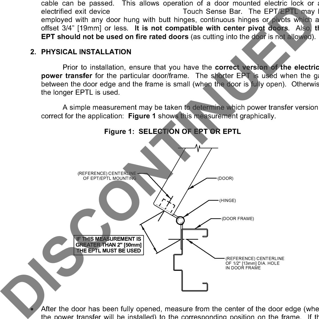
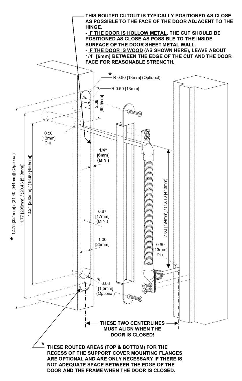
1. Using a router, cut the 1.00" [25mm] wide X 0.67" [17mm] (minimum depth) slot into the edge of the door as shown in Figure 3. Note that the slot should be located as close to the face of the door which carries the hinge as possible. If the door is hollow metal, the slot should be positioned right up next to the inner surface of the door wall. If the door is wood, the slot should be inset about 1/4" [6mm] from the door face as this will leave enough wood along the edge of the door to provide a strong installation.
- a. For wooden doors, place the support cover of the unit into place in the routed cut out performed in step 1, and using the oblong hole in the cover, mark center position for the 1/2" [13mm] diameter hole required for the cable. Then drill the 1/2" [13mm] diameter hole through the door.
- 2. Locate and mark the 1/2" [13mm] on the frame, then using a drill bore a 1/2" [13mm] diameter hole through the door frame as shown in Figure 3. Note: The center of this cable hole in the frame must align with the center of the support cover when the door is closed or the EPT/EPTL will not function properly.
- 3. Pull the wire from the door, through the oblong hole in the support cover, into and through the flexible shield and finally through the door frame via the hole drilled in step 2.
- 4. Using a screwdriver and the two (2) mounting screws included, install the support cover into the routed slot in the door and then install the top of the flexible shield through the back of the support cover using its two (2) screws.
Figure 2: EXPLODED ASSEMBLY VIEW OF EPT & EPTL
5. Insert the bottom end of the flexible shield into the frame and mark the two (2) holes of the mounting flange on the frame. Remove the end of the flexible shield from the hole and drill two (2) 7/64" [2,7mm] diameter holes into the frame.
6. Using a screwdriver and the two (2) screws provided, install the bottom end of the flexible shield into the frame. Note that the ends of the shield freely rotate so that they can be positioned (rotated) square prior to being installed into the door and frame respectively.
Figure 3: ROUTING DETAIL
Notes:
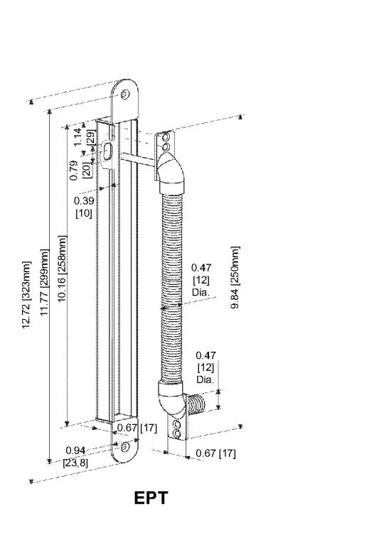
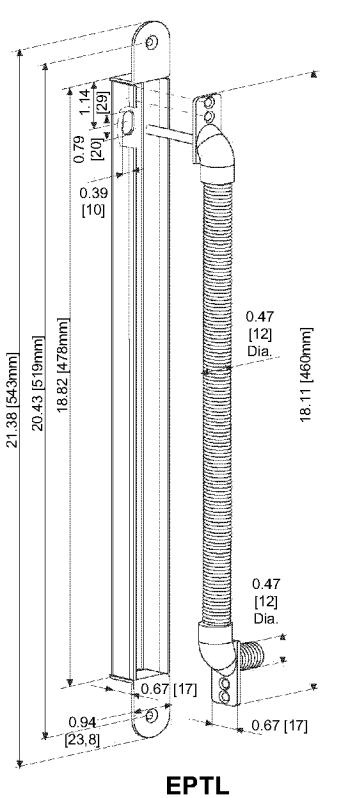
- Dimensions in (Parenthesis) are for EPTL.
- Dimensions in [Brackets] are metric (millimeter).