Corbin Russwin ED8400 Series Exit Device Installation Instructions_FM38
Open the original PDF document
View PDF
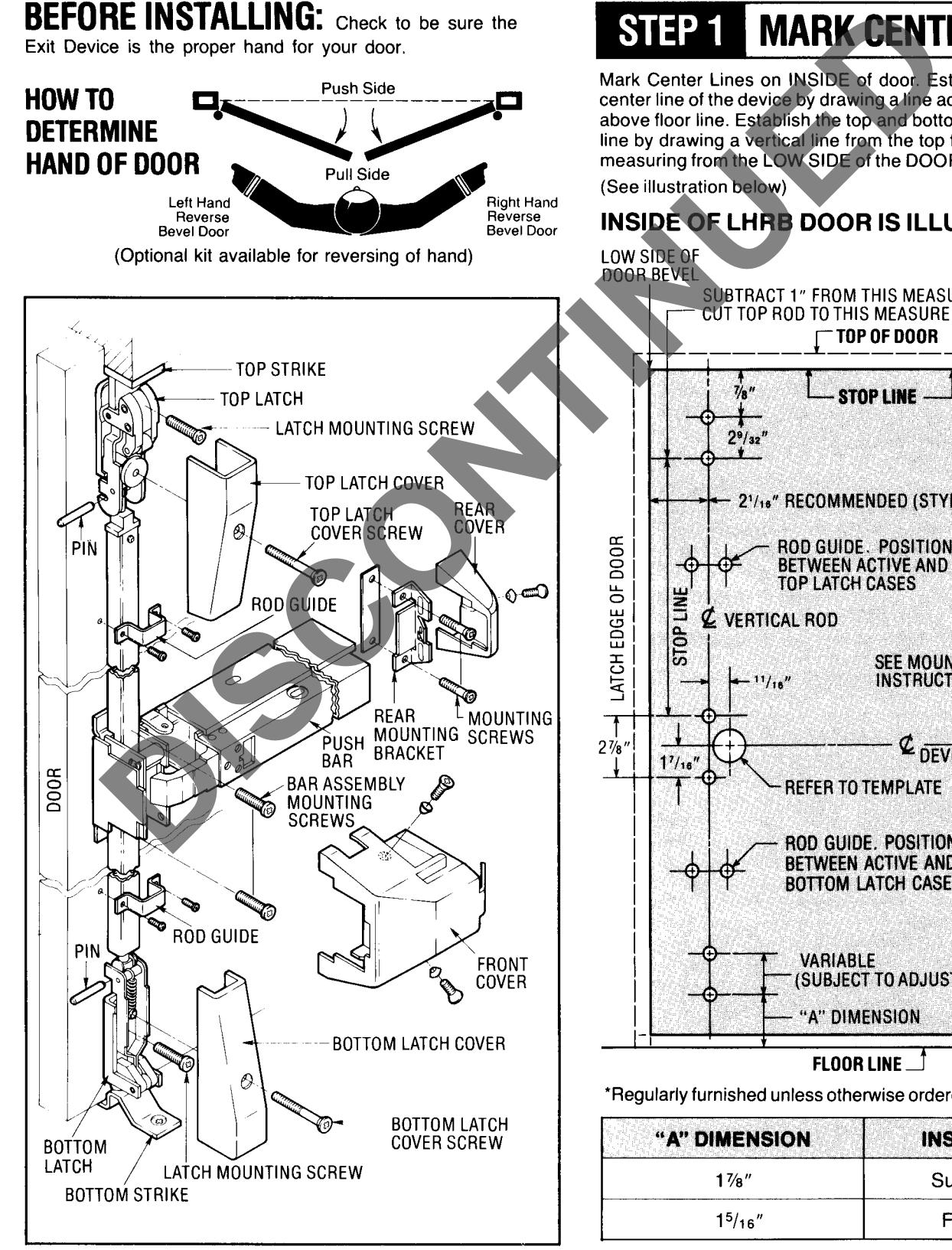
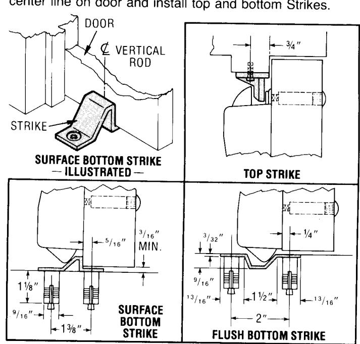
| "A" DIMENSION | INSTALLATION |
|---|---|
| 17⁄8″ | Surface Strike |
| 1 5 / 16 " | Flush Strike |
STEP 2 SPOT AND DRILL TEMPLATE HOLES:
Using Template furnished, spot and drill Mounting Holes for Trim (if furnished), and Device. Be sure the Template is aligned with horizontal and vertical center lines on the INSIDE OF DOOR.
NOTE:
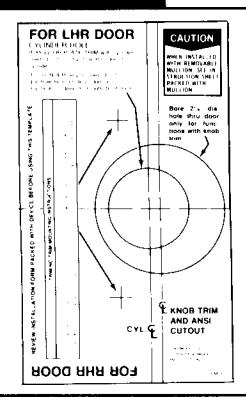
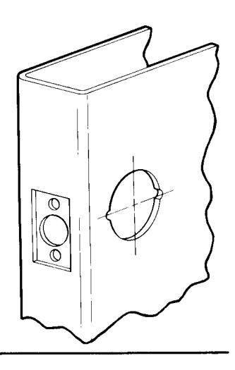
If your door has Cylindrical Lock cutout for ANSI A115.2 and A115.3 ANSI prep doors:
- A. Extend horizontal and vertical center lines of ANSI cut-out as shown at right.
- B. Align ANSI cut-out center lines on template with center lines on door. Spot and drill holes as needed.

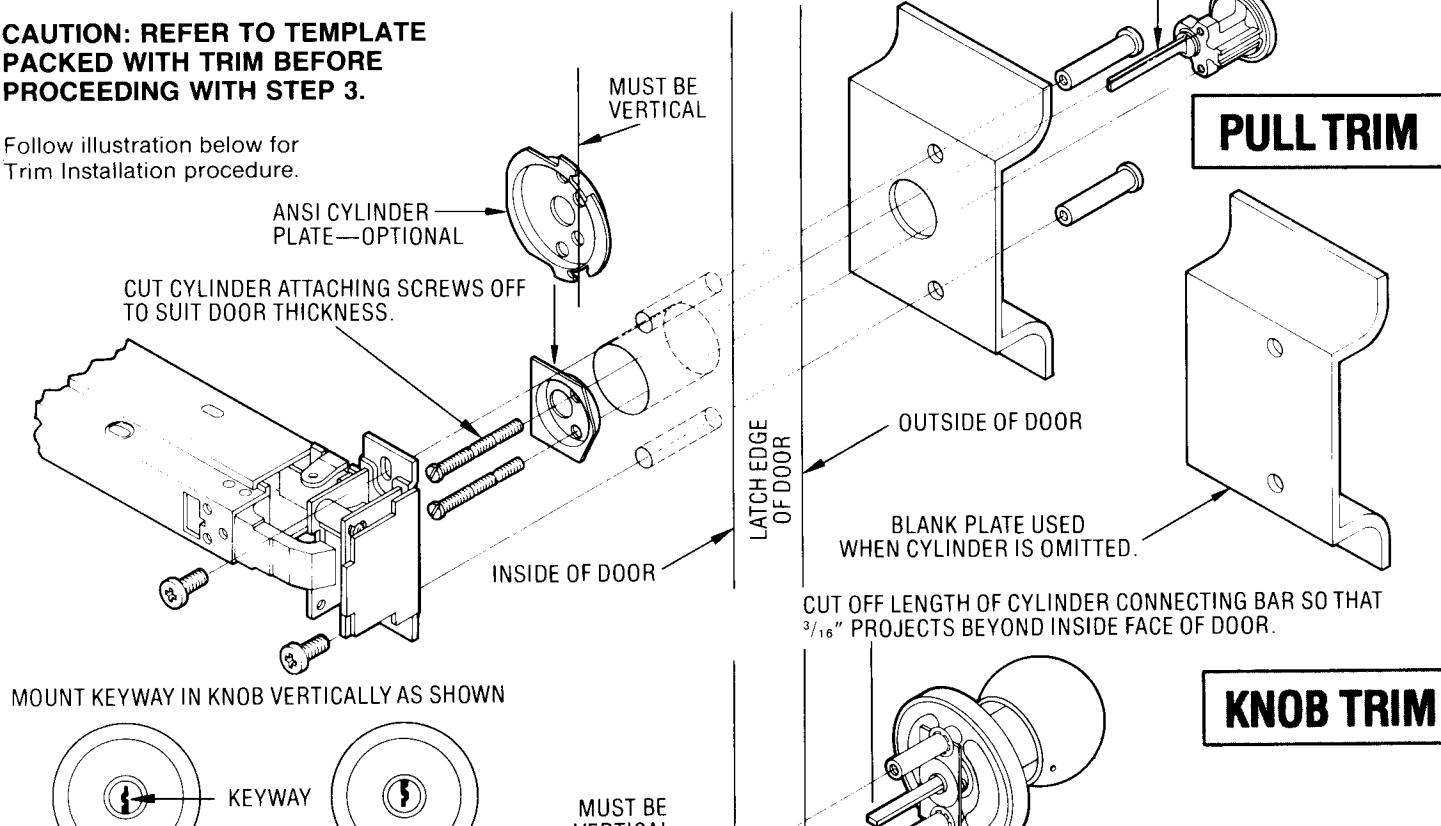
MOUNT CYLINDER HORIZONTALLY AS SHOWN. CUT OFF LENGTH OF CYL. CONNECTING BAR SO THAT 3/16" PROJECTS BEYOND INSIDE FACE OF DOOR.
LATCH EDGE OF DOOR
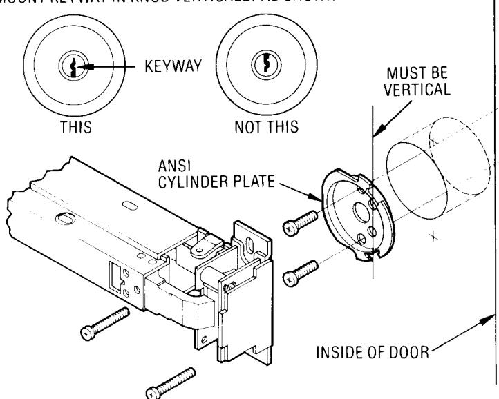
VIEW REVERSED TO SHOW PROPER MATING POSITION WHEN INSTALLED. BOSS BOSS
CAUTION: WHEN USING THE ANSI CYLINDER PLATE BE SURE THE BOSSES ON THE LATCH ASSEMBLY FIT INTO THE CUTOUTS ON THE
STEP 4 LOCATE LATCHES:
Locate Top and Bottom Latch. Mark for later installation. (See illustration on Page 1 for dimensions and locations.)
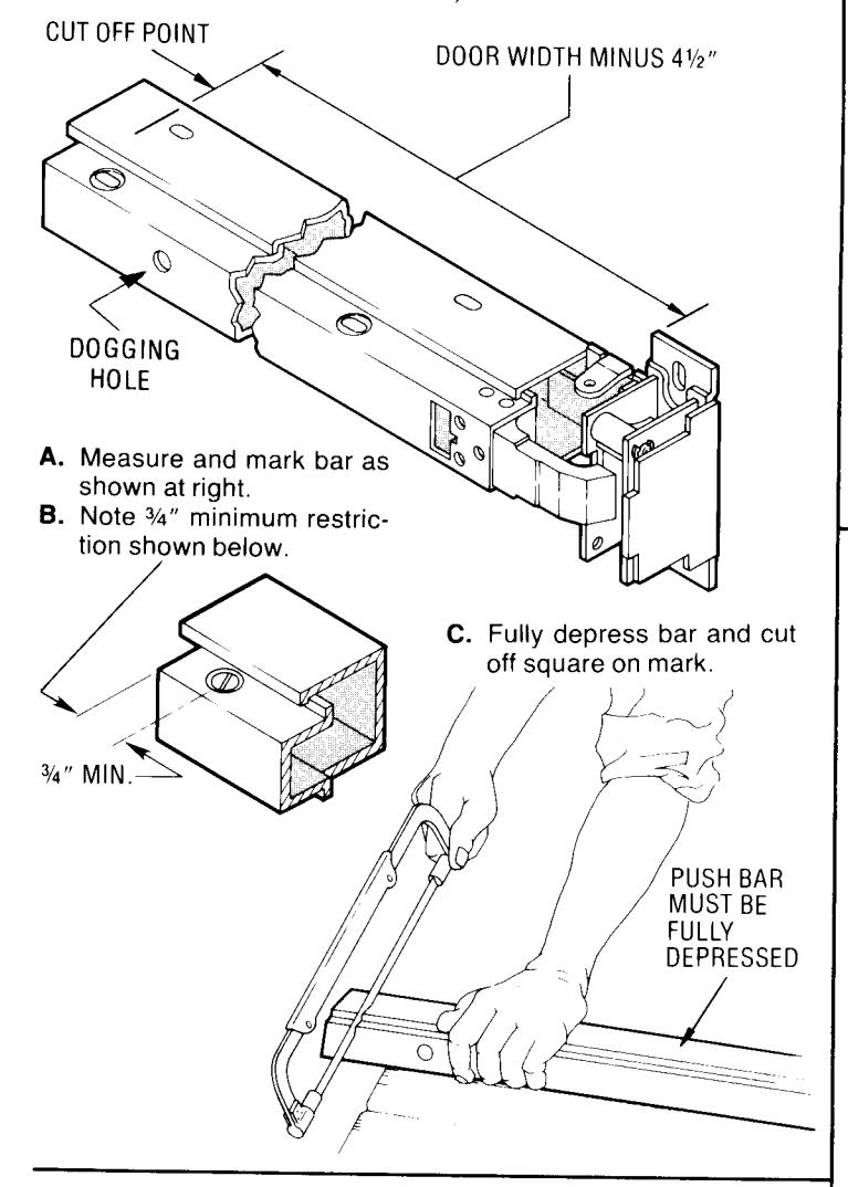
STEP 5 CUT PUSH BAR:
Follow illustration below. (IF BAR DOES NOT REQUIRE CUTTING, PROCEED TO NEXT STEP.)
STEP 6 MOUNT DEVICE:
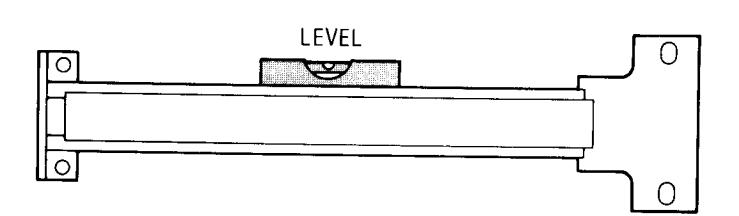
Attach Bar Assembly to door, but do not tighten screws. Assemble Rear Mounting Bracket to Push Bar (see nesting arrangement in exploded view on Page 1). Use Rear Mounting Bracket as a template to spot holes for Mounting Screws. Push Bar should be level. Drill Screw holes and attach Rear Mounting Bracket and Plate to door. Secure Front Plate Screws.
STEP 7 INSTALL STRIKES:
Close door. Align center of Strike with Vertical Backset center line on door and install top and bottom Strikes.
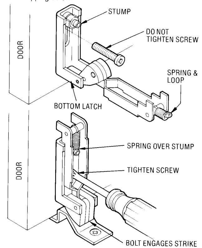
STEP 8 MOUNT BOTTOM LATCH:
Insert Bottom Latch Screw through slot in Latch Frame into bottom hole. Do not tighten. Lift up Slide Assembly and fit the Spring Loop over the stump on the latch frame. Position Latch Frame so that Latch engages strike. Now tighten bottom screw.
Drill a hole for the Cover Screw, using the hole in the Slide Assembly at top as guide. Spot with drill. Drill through with #3 drill for self-tapping screw.
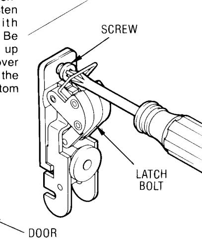
MOUNT TOP LATCH:
Retract the latch by pushing up on slide and fasten Latch Assembly with screws as illustrated. Be sure to draw the screw up tight. Drill hole for the cover screw, using the hole in the Slide Assembly at bottom as quide.
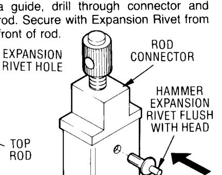
STEP 10 TOP ROD ASSEMBLY:
Measure distance from BOTTOM BOD CONNECTOR SCREW HOLE of Top Latch Case to TOP SCREW HOLE in Active Case. Cut UNDRILLED END of top rod to this Length minus 1". (See illustration on Page 1.) Seat Adjustable Rod Connector in cut end of rod. Using hole as a guide, drill through connector and rod. Secure with Expansion Rivet from front of rod. EXPANSION
TOP
ROD
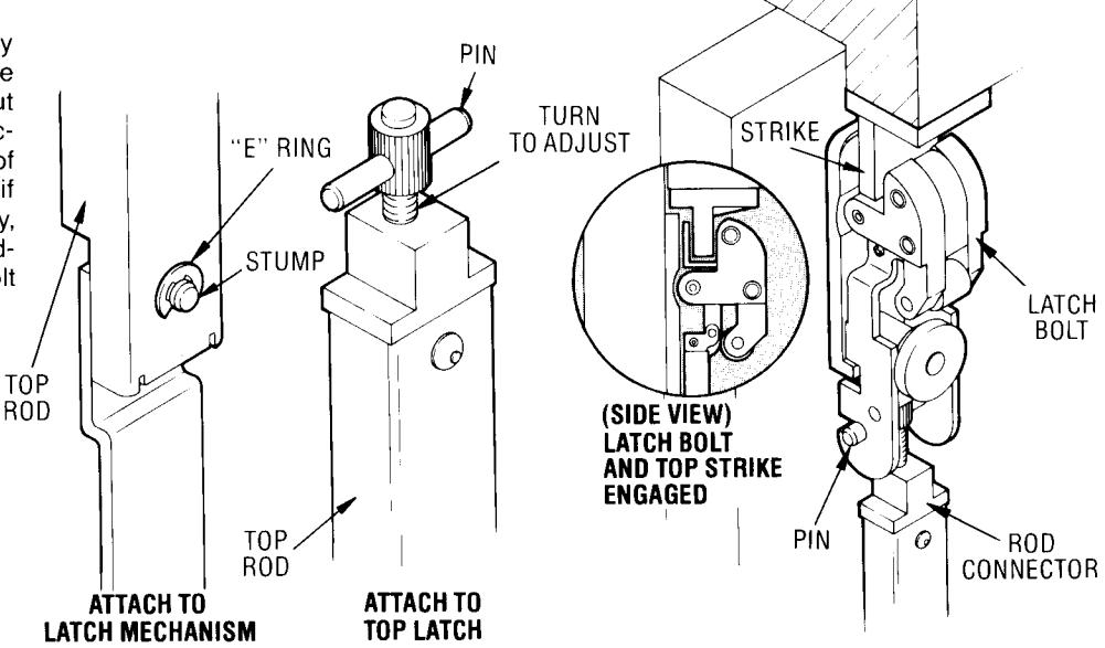
INSTALL TOP ROD AND ADJUST TOP LATCH:
Attach Top Rod to Bar Assembly by slipping hole over Stump and secure Rod by means of "E" Ring. Shut door. Turn Adjustable Rod Connector until head touches underside of latch slide. Insert pin. Depress bar, if top latch does not retract completely, remove pin and turn connector to adjust length. Repeat until Latch Bolt iust disengages.
CAUTION: MAKE CERTAIN "E" RING ENGAGES SLOT IN STUMP.
0
STEP 12 INSTALL AND ADJUST BOTTOM ROD:
Attach Bottom Rod to Bar Assembly by slipping hole over Stump and secure Rod by means of "E" Ring. Shut door. Dog down Active Case. Insert pin into Rod Connector. Turn Adjustable Rod Connector by turning clockwise or counter clockwise until Latch Bolt just clears Strike. Undog Device.
BOTTOM ROD
CAUTION: MAKE CERTAIN "E" RING ENGAGES SLOT IN STUMP.
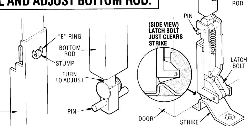
ATTACH TO LATCH MECHANISM
ATTACH TO BOTTOM LATCH
BOLT JUST CLEARS STRIKE
nh
CH
BOTTOM
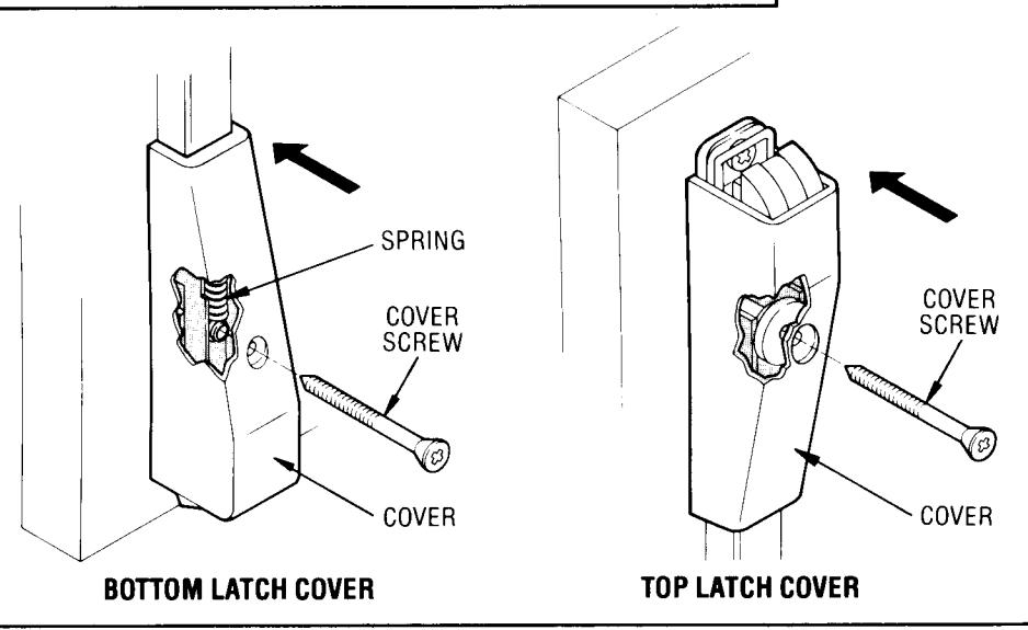
STEP 13 MOUNT TOP AND BOTTOM LATCH COVERS:
Bottom Cover —Position above Bottom Latch Frame align with hole in slide assembly at bottom. Secure with furnished screw.
Top Cover —Position and secure with screw through bottom hole in Top Latch Frame.
STEP 14 TEST PUSH BAR AND DOGGING OPERATIONS:
The latches should engage the strikes when the door is closed. If the door can be pushed open without depressing the push bar the top rod connector has been over adjusted. Remove cover. Adjust connector as needed. Replace cover.
The top and bottom latches should disengage from the strikes freely when the push bar is depressed or dogged down. If they do not disengage, remove the covers and adjust the connectors as needed. Replace the covers. Retest for proper operation.
NO-TRIM SERIES:
Top and bottom latch bolts are retracted by the push bar inside.
PLATE OR PULL TRIM SERIES:
Top and bottom latch bolts are retracted by the push bar inside and the key outside. Turning the key in either direction will retract the latches. Return key to the horizontal position to remove key and project latches.
KNOB TRIM SERIES:
Top and bottom latch bolts are retracted by the push bar inside and the key or knob outside.
To lock knob: Insert key in cylinder and turn counterclockwise as far as key will turn. Then return key to its vertical position and withdraw key.
To unlock knob: Insert key in cylinder and turn clockwise as far as key will turn (the latches will retract during this procedure). Then return key to its vertical position and withdraw key.
DOGGING: Depress push bar. Insert dogging wrench and turn clockwise 90°. The push bar will remain depressed and the latches will remain retracted.
STEP 15 MOUNT ROD GUIDES:
Place Guides over the rod. (One above the Bar Assembly and One below the Bar.) Be sure the Guides will not bind against the rods. Use holes in the Guides to spot screw location. Drill holes and secure the Guides to the door.
Check to be certain the rods move freely.
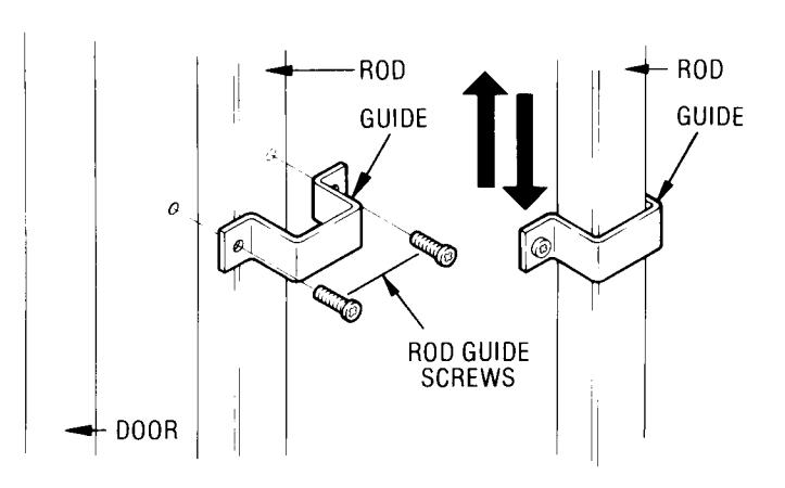
RODS MUST MOVE
TO REMOVE AND REINSTALL CYLINDER IN KNOB:
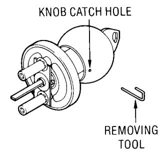
REMOVE KNOB:
- 1. Insert key in cylinder and turn 90° clockwise.
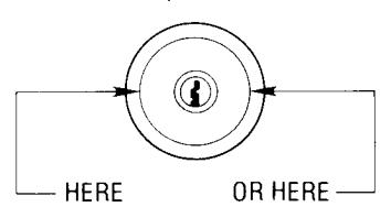
- 2. Insert knob removing tool into the hole in the knob and depress the knob catch button.
- 3. While knob catch button is depressed pull knob off.
(The knob catch button will be in one of these positions).
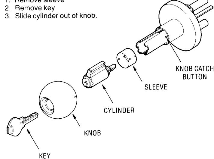
REINSTALL CYLINDER IN KNOB:
- 1. Slide cylinder into knob.
- 2. Replace sleeve.
REINSTALL KNOB:
- 1. With key inserted part way into cylinder slide knob onto knob
- Depress knob catch button and push knob on to the knob shank as far as it will go.
- Insert key completely into the cylinder and turn the key while

1. Remove sleeve
pushing on the knob until it engages the knob catch button.
- 4. Return key to its vertical position and remove it.
- 5. Pull on the knob to be certain it is properly engaged to the knob catch button.
| SCREW CHART | ||
|---|---|---|
| Item | Qty. | Fastener |
| Top strike | 2 | 12-24 ½" Lg. pan head machine screw or #12 1½" Lg. round head wood screws |
|
Top and bottom
latch |
2 | " Lg. binding head machine screws and sex nuts P/N 101F74 or #14 3/4" Lg. pan head wood screws |
| Top latch cover | 1 | " Lg. oval head machine screw and sex nut P/N 101F74 or #14 " Lg. oval head wood screw |
| Top and bottom rod guides | 4 | #8×¾" Lg. round head tapping screws type "A" |
|
Front plate
assembly and rear bracket |
4 | " Lg. pan head machine screw and sex nuts P/N 376F37 or #12 × 11/4" Lg. pan head tapping screws type "A" |
|
Bottom Latch
Cover |
1 | -20 2" Lg. oval head tapping screw type "F" or #14 2½" Lg. oval head wood screw. |
| Bottom Strike | 2 | Lg. flat head machine screws and anchors P/N 361F30 or 14 11/4 flat head wood screws |
Drill sizes for screws and sex nuts cannot be recommended because various factors, such as type of door and frame construction, thickness and type of metal, etc. can affect the final hole diameter and resulting holding strength of the fastener.