Corbin Russwin ED8000 Series ED8400A Wide Stile SVR Installation Instructions_FM126
Open the original PDF document
View PDF

Copyright © 2018, 2019, ASSA ABLOY Access and Egress Hardware Group, Inc. All rights reserved. Reproduction in whole
or in part without the express written permission of ASSA ABLOY Access and Egress Hardware Group, Inc. is prohibited.
reproductive harm. For more information go to www.P65warnings.ca.gov.
ED8400A Series
Exit Device
Installation Instructions

| TOC | Table of Contents | |
|---|---|---|
| 1 | Preparing for Installation 3 | |
| a | Mark Centerlines 3 | |
| 2 | Installation 4 | |
| a | Spot and Drill Template Holes 4 | |
| b | Cut Pushbar (if required) 5 | |
| c | Mount Exit Device - For Reinforced Metal Doors Only5 | |
| d | Mount Exit Device - For All Other Door Types 6 | |
| e | MountTop and Bottom Latches 7 | |
| f | Install Bottom Strike 7 | |
| g | Install Top Strike 8 | |
| h | Assemble Top Rod 8 | |
| i | Install Top Rod and Adjust Top Latch 9 | |
| j | Install Bottom Rod and Adjust Bottom Latch 9 | |
| k | Install Top and Bottom Latch Covers | 10 |
| l | Install Pushbar Covers | 10 |
| m | Test Pushbar Operation | 11 |
| n | Mount Rod Guides | 11 |
| 3 | Fastener Chart | 12 |


IMPORTANT
- Failure to follow these instructions could affect operation of this product and void the warranty.
- Some trim designs are handed when used with this device (see trim instructions).
- Exit devices must be securely fastened to properly reinforced doors with fasteners that will not loosen or pull out. Add reinforcement when necessary.
- Before Installing: Check to be sure exit device is the proper hand for your door.
1 Preparing for Installation
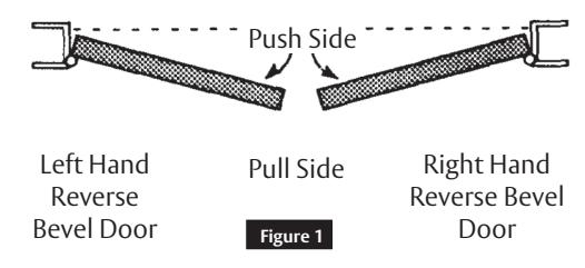
How to Determine Hand of Door (Figure 1)
a Mark Centerlines
Mark centerlines on INSIDE of door
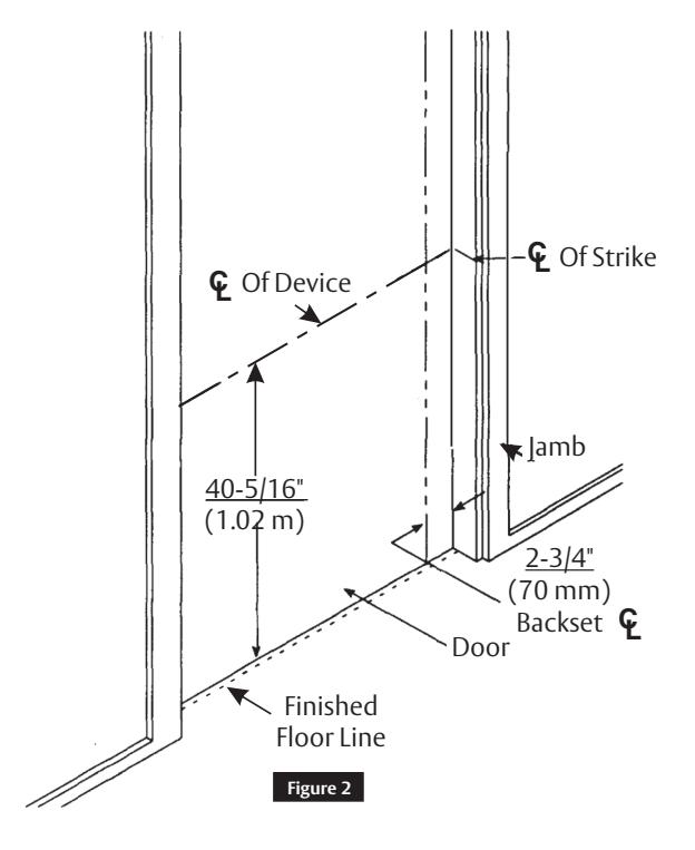
- 1. Establish centerline of device by drawing a line across door and stop 40-5/16" (1.02 m) above finished floor. (Figure 2)
- 2. Using "Easy-Spot" Template Locater (enclosed), establish the device 2-3/4" (70 mm) backset centerline by drawing a vertical line from top to bottom of door measuring from centerline of door bevel.

2 Installation
a Spot and Drill Template Holes
Using templates (Figure 3, Figure 4), spot and drill mounting holes for trim (if furnished) and device. Be sure template is aligned with horizontal and vertical centerlines on inside of door.
For Reinforced Metal Doors: Using templates provided, spot, drill, and tap all holes marked A and C for machine screws. Spot and drill 1/4" (6 mm) holes marked B through door. Enlarge to 3/8" (10 mm) from opposite side of door to clear for sexnuts.
For All Other Doors: Using templates provided, spot and drill all 1/4" (6 mm) holes marked B through door. Enlarge to 3/8" (10 mm) from opposite side of door to clear for sexnuts. Spot, drill, and tap two (2) holes marked A for machine screws or tapping screws. If trim is used, spot drill and tap holes marked C for tapping screws.
For Exit Only Applications: On holes marked C , drill 1/4" (6 mm) holes through door. Enlarge to 3/8" (10 mm) from opposite side of door to clear for sexnuts.
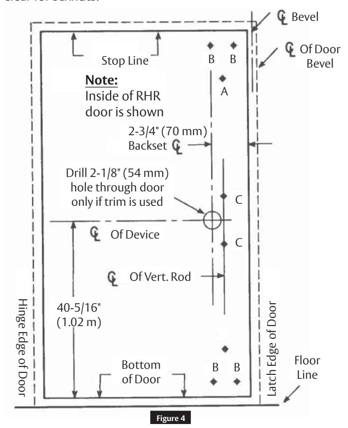
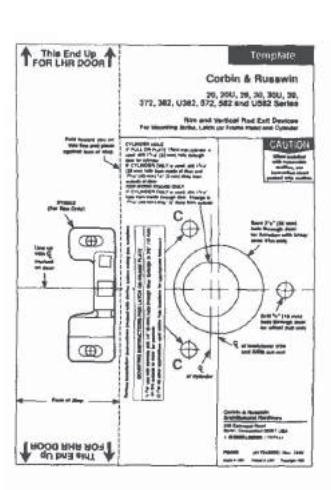
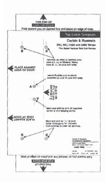
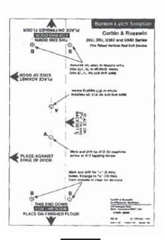
Figure 3

2 Installation (cont.)
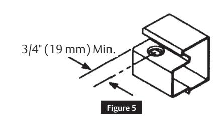
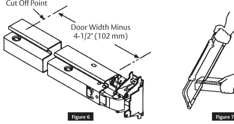
b Cut Pushbar (if required)
If bar does not require cutting, proceed to step 2e.
- 1. Note 3/4" (19 mm) minimum restriction. (Figure 5)
- 2. Measure and mark bar as shown. (Figure 6)
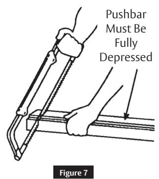
- 3. Fully depress bar and cut off square on mark. (Figure 7)
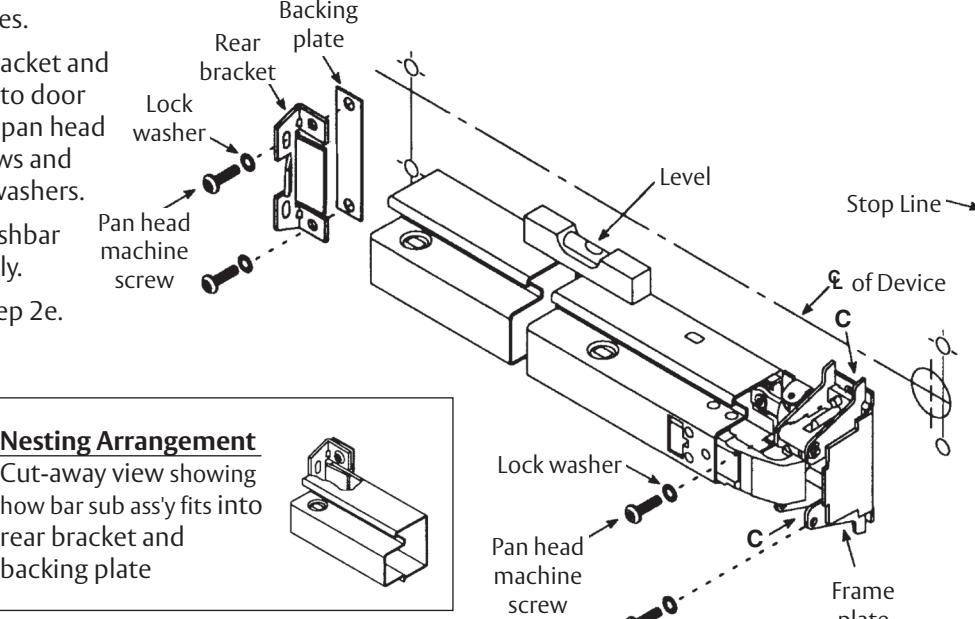
c Mount Exit Device - For Reinforced Metal Doors Only
Note: For all other door types, proceed to Step 2d
- 1. If trim is used, install trim first, then install device with two (2) pan head machine screws and two (2) lock washers (or throughbolting screws packed with trim) in frame plate assembly holes marked C . (Figure 8) Use level as shown to ensure device is level.
- 2. Use rear bracket to spot, drill, and tap two (2) rear bracket mounting holes.
- 3. Attach rear bracket and backing plate to door using two (2) pan head machine screws and two (2) lock washers.
- 4. Tighten all pushbar screws securely.
- 5. Proceed to Step 2e.
FM126 05/19
plate assembly
Figure 8

2 Installation (cont.)
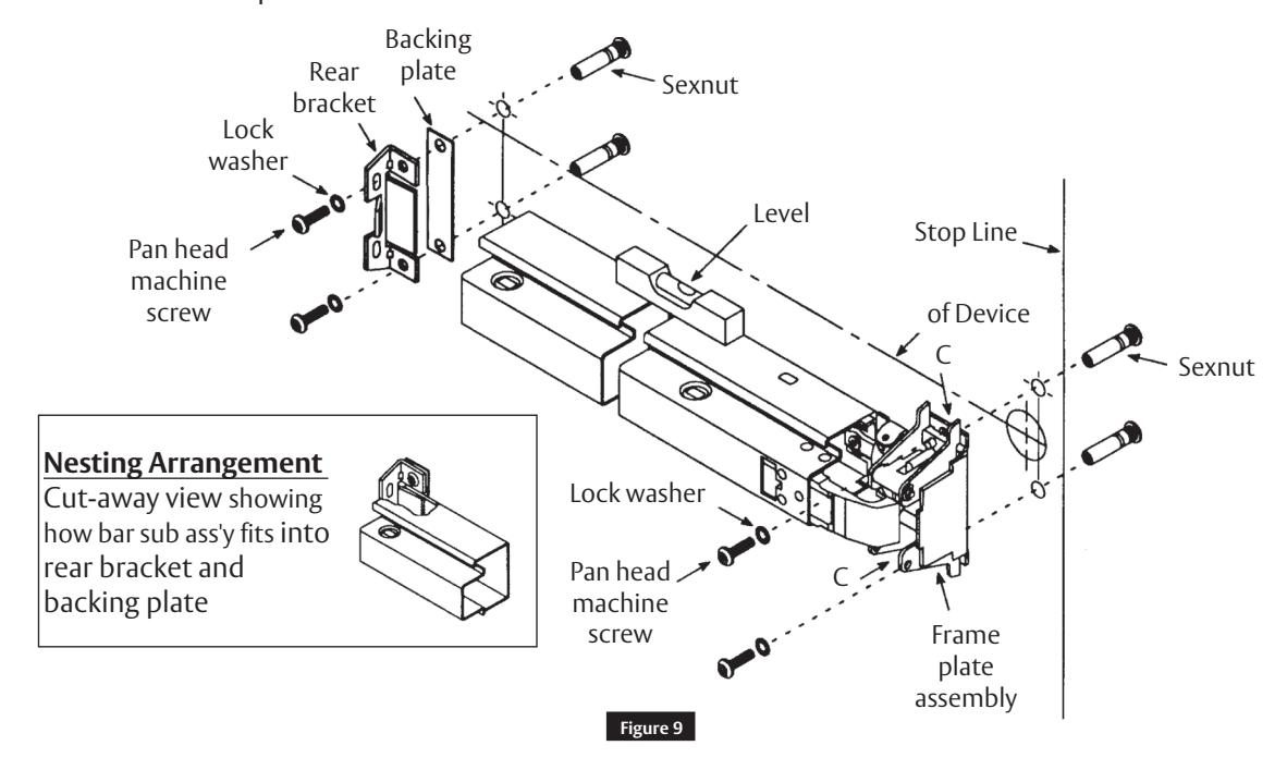
d Mount Exit Device - For All Other Door Types
Note: For all other door types, see Step 2c.
- 1. If trim is used, install trim first, then install device with two (2) pan head machine screws, two (2) lock washers and two (2) sexnuts (or throughbolting screws packed with trim) in latch assembly holes marked C. (Figure 9) Sexnuts for holes marked C are not required and cannot be used with throughbolted escutcheon and rose trims. Use level as shown to ensure device is level.
- 2. Use rear bracket to spot and drill 1/4" (6 mm) holes through door. Enlarge holes to 3/8" (10 mm) from opposite side of door to clear for sexnuts and bolts.
- 3. Attach rear bracket and backing plate to door using two (2) pan head machine screws, two (2) lock washers, and two (2) sexnuts.
- 4. Tighten all pushbar screws securely.
- 6. Proceed to Step 2e.

2
Installation (cont.)
e
MountTop and Bottom Latches
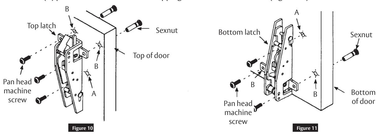
- 1. Install top latch using two (2) pan head machine screws and two (2) sexnuts in holes marked B and one (1) pan head machine screw or tapping screw in hole marked A . (Figure 9)
- 2. Install bottom latch using two (2) pan head machine screws and two (2) sexnuts in holes marked B and one (1) pan head machine screw or tapping screw in hole marked A. (Figure 10)
f
Install Bottom Strike
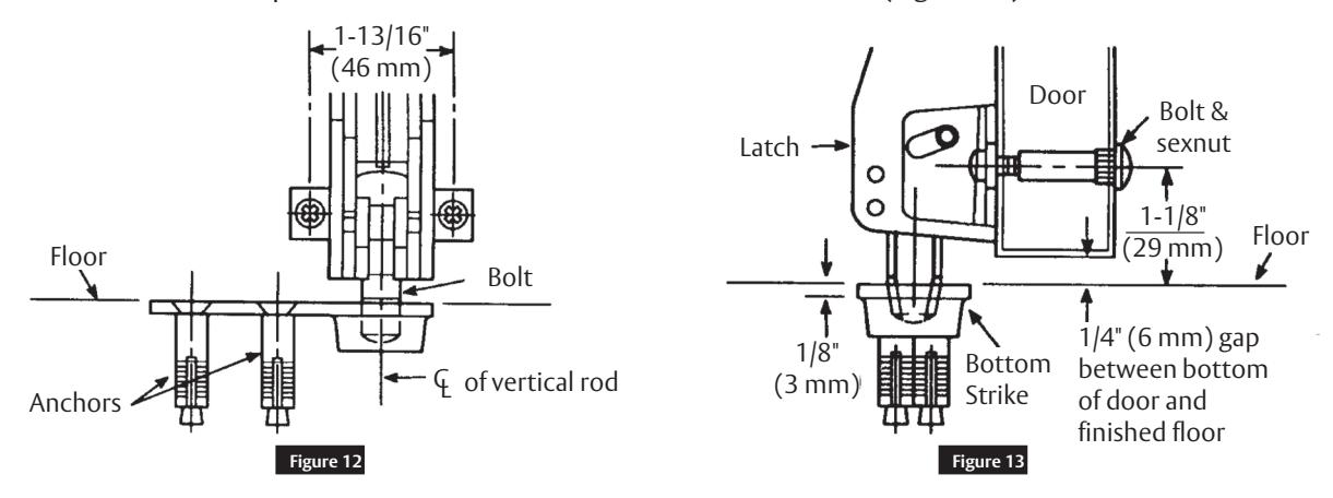
- 1. Using the strike as a template, mortise bottom strike into the floor, lining up carefully with the latchbolt centerline. (Figure 12)
- 2. Use anchors or equivalent to secure the flat head screws into floor. (Figure 13)

2 Installation (cont.)
g Install Top Strike
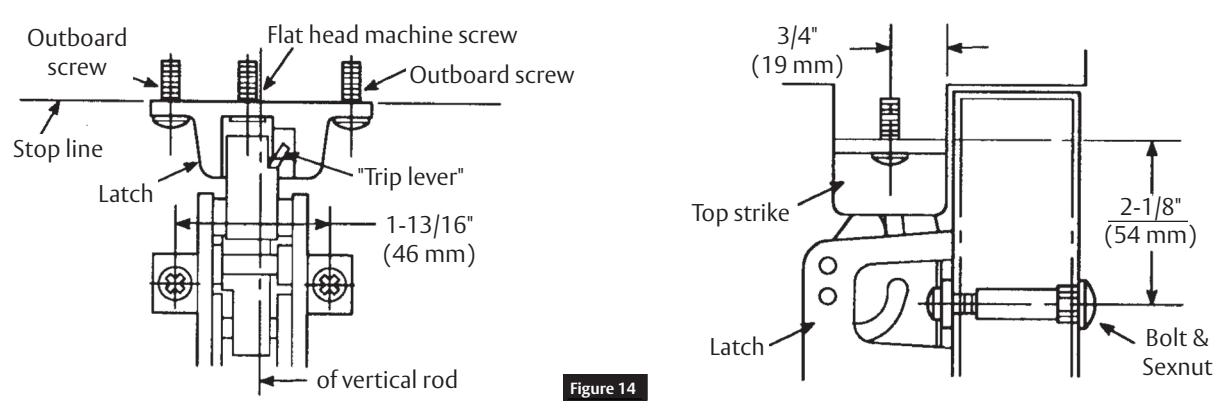
- 1. Align the strike with the latch and use the strike as a template to spot, drill, and tap the two (2) outboard screws through outboard slots.
- 2. Fasten the top strike to frame with two (2) pan head outboard screws but do not fully tighten them. (Figure 14)
- 3. Adjust the strike so the latch engages it fully without binding when the door is closed.
- 4. Push up on the latch to make sure that the latchbolt retracts to allow the door to open.
- 5. Tighten the two (2) outboard screws.
- 6. Spot, drill, and tap one (1) flat head machine screw in center of the strike.
- 7. Install the screw and tighten securely.
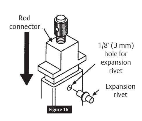
h Assemble Top Rod
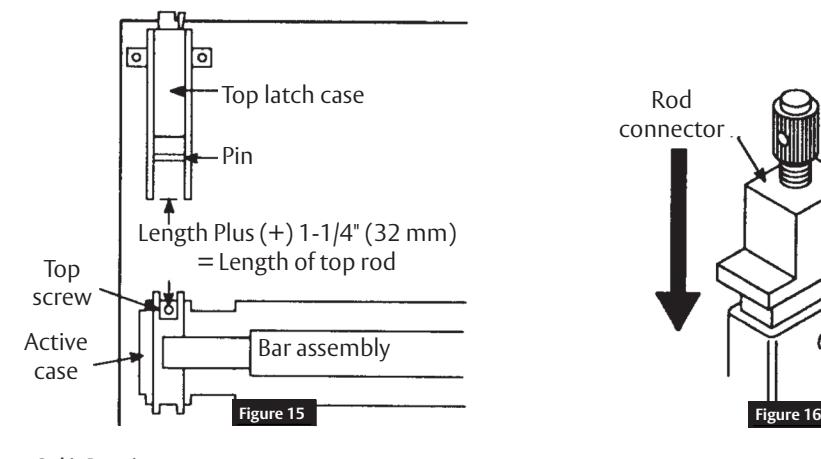
- 1. Measure the distance from the bottom of the top latch case to the centerline of the top screw in device active case. (Figure 15)
- 2. Cut the undrilled end of the top rod to this length plus (+) 1-1/4" (32 mm).
- 3. Seat adjustable rod connector in cut end of rod.
- 4. Using the hole in connector as a guide, drill 1/8" (3 mm) hole through rod.
- 5. Install expansion rivet from the front of the rod through the rod connector. (Figure 16)

2 Installation (cont.)
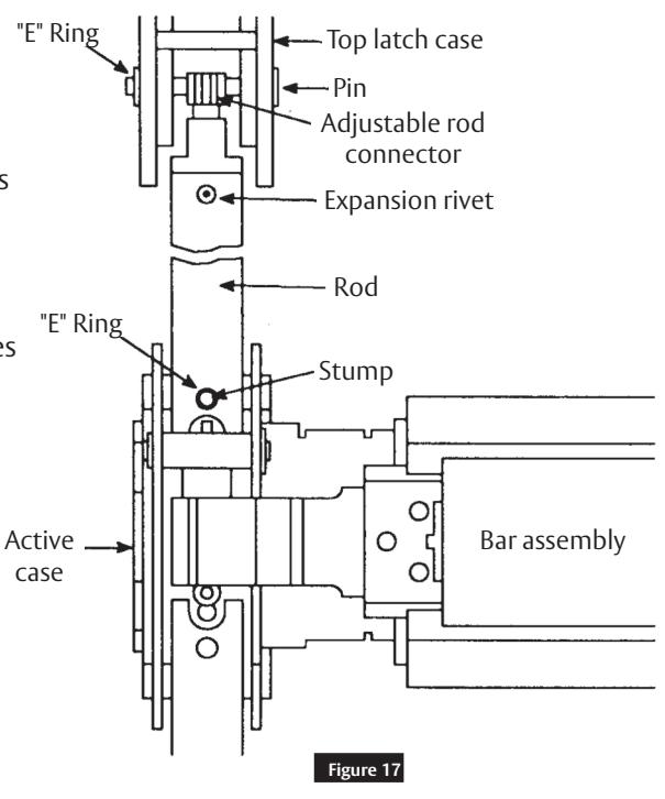
i Install Top Rod and Adjust Top Latch
- 1. With door closed and latched, attach the top rod to the bar assembly by slipping the hole in rod over stump on active case and secure the rod with the "E" ring. Make certain "E" ring engages slot in the stump. (Figure 17)
- 2. Remove the "E" ring holding pin in the top latch and remove pin.
- 3. Turn the adjuster so that the hole aligns with holes in sides.
- 4. Insert pin.
- 5. Shut the door.
- 6. Depress the pushbar.
- 7. If the top latch does not retract completely, and does not remain in retracted position, remove the pin and turn the connector to adjust length. Repeat until the latchbolt operates correctly.
- 8. Secure the pin with "E" ring. The "E" ring should engage the slot in the pin.
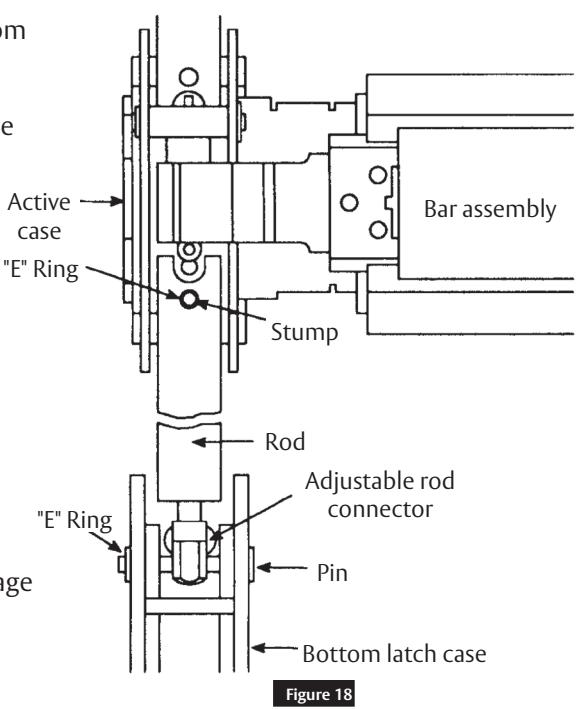
j Install Bottom Rod and Adjust Bottom Latch
- 1. With the door closed and latched, attach the bottom rod to the bar assembly by slipping the hole in rod over the stump on active case and secure the rod with the "E" ring. ensure that the "E" ring engages the slot in the stump. (Figure 18)
- 2. Remove the "E" ring holding the pin in the bottom latch and remove the pin.
- 3. Turn adjuster at the bottom of the rod so that the holes align with the holes in the latch sides.
- 4. Insert the pin.
- 5. Depress the pushbar.
- 6. If the bottom latchbolt does not clear the strike, remove the pin and turn the connector to adjust the length. Repeat until the latchbolt just clears the strike.
- 7. Secure the pin with the "E" ring. "E" ring should engage the slot in the pin.

2 Installation (cont.)
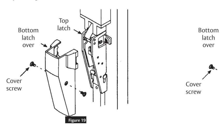
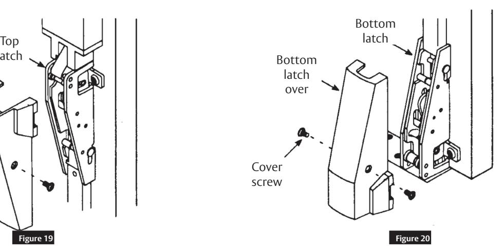
k Install Top and Bottom Latch Covers
- 1. Position the top latch cover and secure in the top latch frame. (Figure 19)
- 2. Position the bottom latch cover and secure in the bottom latch frame. (Figure 20)
Note:
When tightening top and bottom latch covers, tighten screws equally. DO NOT over torque one side only - it might create a bind on the rod.
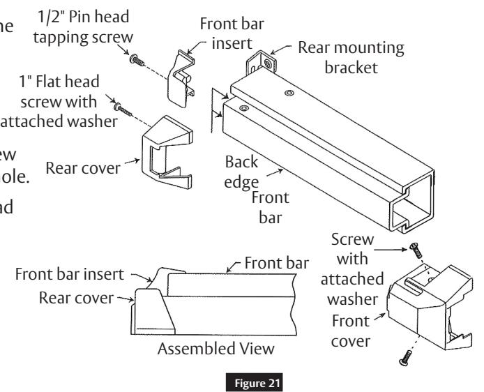
l Install Pushbar Covers
- 1. Slide the front bar insert over the end of the front bar.
- 2. Insert the 1/2" pan head tapping screw through the mounting hole.
- 3. While holding the insert flush against the back edge of the front bar, tighten the screw to the bottom of the recessed mounting hole.
- 4. Install front and rear covers ith a 1" flat head screw with attached washer. (Figure 21)

2
Installation (cont.)
m
Test Pushbar Operation
Latches should engage the strikes when the door is closed. If the door can be pushed open without depressing the pushbar, the top rod connector has been over adjusted.
- 1. Remove the cover.
- 2. Adjust the connector as needed.
- 3. Replace the cover.
The top and bottom latches should disengage from strikes freely when the pushbar is depressed. If they do not disengage:
- 1. Remove the covers.
- 2. Adjust the connector as needed.
- 3. Replace the covers.
Note:
Retest and adjust until proper operation is achieved.
n
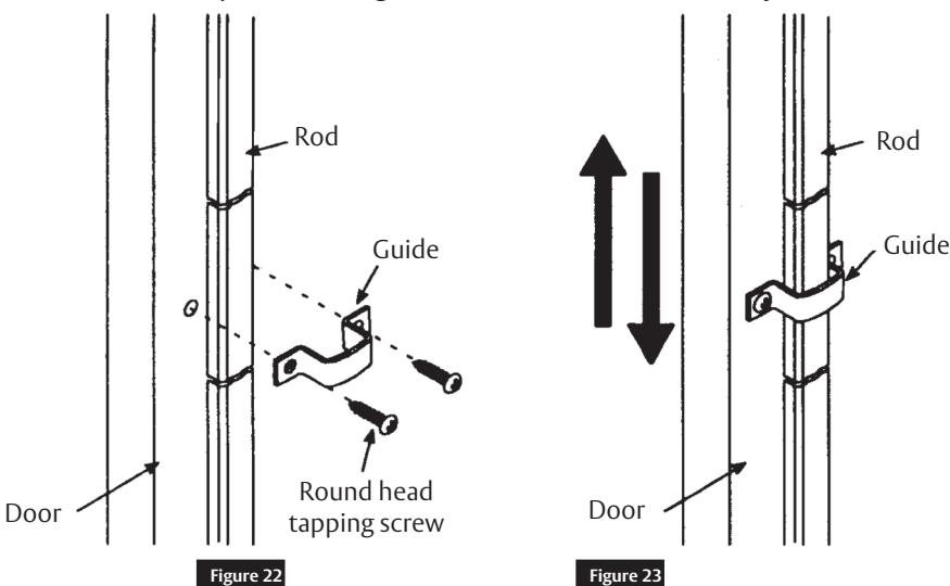
Mount Rod Guides
- 1. Place the guides over the rods (midway between bar assembly and top and bottom latches). Be sure that the guides will not bind against the rods. Use holes in guides to spot screw locations.
- 2. Drill holes and secure guides to the door using round head tapping screws. (Figure 22)
Note:
The rods must move freely up and down. (Figure 23)
If the rods bind, reposition the guides until the rods move freely.
11

3 Fastener Chart
| Item | Qty | Fastener |
|---|---|---|
| Frame Plate Assembly | 2 | #12-24 x 3/4" Phillips Flat Head Machine Screw |
| 2 | #12 Internal Tooth Lock Washer | |
| Rear Bracket | 2 | #12-24 x 3/4" Phillips Pan Head Machine Screw |
| 2 | #12 Internal Tooth Lock Washer | |
| Top Strike | 2 | #12-24 x 3/4" Phillips Pan Head Machine Screw |
| 1 | #12-24 x 7/8" Phillips Flat Head Machine Screw | |
| Bottom Strike | 2 | 1/4-20 x 5/8" Phillips Flat Head machine Screw |
| 2 | Anchor | |
| 3 | #12-24 x 3/4" Phillips Flat Head Machine Screw | |
| Top Latch | (For wood door - 1 #12 Pan Head Tapping Screw) | |
| 3 | #12-24 x 3/4" Phillips Flat Head Machine Screw | |
| Bottom Latch | (For wood door - 1 #12 Pan Head Tapping Screw) | |
| Top Latch Cover | 2 | Oval Head Screw with Attached Washer |
| Bottom Latch Cover | 2 | Oval Head Screw with Attached Washer |
| Front Cover | 2 | #8-32 x 1/2" Screw with Attached Washer |
| Rear Cover | 1 | #8-32 x 1/2" Screw with Attached Washer |
| Rod Guides | 4 | #8-3/4" Phillips Round Head, Type A Tapping Screw |
| Non-Reinforced Door | 8 | #12-24 (3/8" dia.) Sexnut |
Corbin Russwin, Inc. 225 Episcopal Road Berlin, CT 06037 USA Phone: 800-543-3558 Fax: 800-447-6714 www.corbinrusswin.com
ASSA ABLOY is the global leader in door opening solutions, dedicated to satisfying end-users needs for security, safety, and convenience