Corbin Russwin ED8000 Series ED8400 Wide Stile SVR Non-Reversible Installation Instructions_FM22
Open the original PDF document
View PDF

ED8400 Series
Non-Reversible
Vertical Rod Exit Devices

This product can expose you to lead which is known to the state of California to cause cancer and birth defects or other reproductive harm. For more information go to www.P65warnings.ca.gov.
ED8400 Series
Vertical Rod Exit Devices
Installation Instructions

| TOC | Table of Contents | |
|---|---|---|
| 1 | Pre-Installation 3 | |
| 2 | Door Preparation 4 | |
| a | Mark Centerlines 4 | |
| b | Spot and Drill Template Holes 5 | |
| 3 | Installation 6 | |
| a | Install Trim 6 | |
| b | Locate Latches 6 | |
| c | Cut Pushbar 7 | |
| d | Mount Device 7 | |
| e | Install Strikes 8 | |
| f | Mount Bottom Latch 9 | |
| g | Mount Top Latch9 | |
| h | Top Rod Assembly | 10 |
| i | Install Top Rod and Adjust Top Latch | 10 |
| j | Install and Adjust Bottom Rod | 11 |
| k | Mount Top and Bottom Latch Covers | 11 |
| l | Test Pushbar and Dogging Operations | 12 |
| m | Mount Rod Guides | 12 |
| 4 | Remove and Reinstall Cylinder In Knob | 13 |
Vertical Rod Exit Devices
Installation Instructions

1
Pre-Installation
Installation for wood and metal doors. Check that Exit Device is the proper hand for your door. Optional kit is available for reversing of hand.
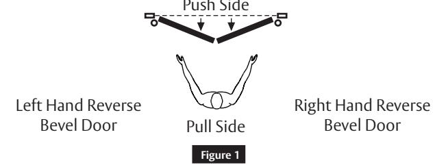
How to determine hand of door (Figure 1)

2 Door Preparation
a Mark Centerlines
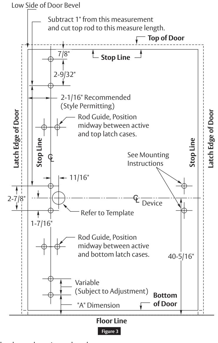
Mark centerlines on INSIDE of door. Establish the horizontal centerline of the device by drawing a line across the door 40-5/16" above floor line. Establish the top and bottom rod backset centerline by drawing a vertical line from the top to bottom of the door measuring from the low side of the door bevel. (Figure 3)
Inside of LHRB Door is Illustrated
*Regularly furnished unless otherwise ordered.
| "A" Dimension | Installation |
|---|---|
| 1-7/8" | Surface Strike |
| 1-5/16" | Flush Strike |
4

2 Door Preparation (cont.)
a Mark Centerlines (cont.)
Screw Chart
Various factors prevent recommendation of drill sizes for screws and sex nuts; such as type of door and frame construction. Thickness and type of metal, etc. can affect the final hole diameter and resulting holding strength of the fastener.
| Item | Fastener | |
|---|---|---|
| Top Strike |
12-24 x 1/2" Lg. Pan Head Machine Screw or #12 x 1-1/4" Lg. Round
Head Wood Screw |
|
| Top and Bottom Latch |
1/4-20 x 3/4" Lg. Binding Head Machine Screw and Sex Nut P/N
101F74 or #14 x 3/4" Lg. Pan Head Wood Screw |
|
| Top Latch Cover |
1/4-20 x 1-7/8" Lg. Oval Head Machine Screw and Sex Nut P/N
101F74 or #14 x 2-1/4" Lg. Oval Head Wood Screw |
|
| Top and Bottom Rod Guides | #8 x 3/4" Lg. Round Head Tapping Screw Type "A" | |
| Front Plate Assembly and Rear Bracket | 4 |
12-24 x 3/4" Lg. Pan Head Machine Screw and Sex Nut P/N 376F37
or #12 x 1-1/4" Lg. Pan Head Tapping Screw Type "A" |
| Front Bar Insert | 1/2" Lg. Pan Head Tapping Screw | |
| Rear Cover | 1 | 1" Lg. Flat Head Screw with Washer |
| Bottom Latch Cover | 1 |
1/4-20 x 2" Lg. Oval Head Tapping Screw Type "F" or #14 x 2-1/4" Lg.
Oval Head Wood Screw |
| Bottom Strike |
1/4-20 x 5/8" Lg. Flat Head Machine Screw and Anchors P/N 361F30
or #14 x 1-1/4" Lg. Flat Head Wood Screw |
|
b Spot and Drill Template Holes
Using template furnished, spot and drill mounting holes for trim (if furnished), and device. Be sure the template is aligned with horizontal and vertical centerlines on the inside of door.
Note:
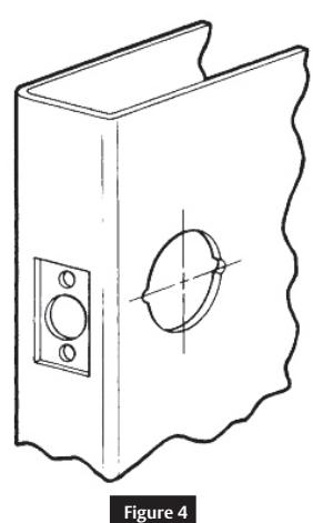
If your door has cylindrical lock cutout for ANSI/BHMA A156.115 prep doors:
- A. Extend horizontal and vertical centerlines of ANSI /BHMA cutout as shown at right.
- B. Align ANSI/BHMA cutout centerlines on template with centerlines on door. Spot and drill holes as needed.

3 Installation
a Install Trim
CAUTION
Refer to the template packed with trim before proceeding with step 3.
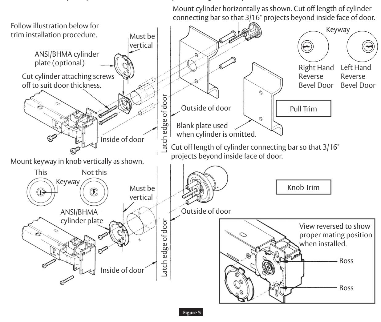
Caution
When using the ANSI/BHMA cylinder plate, be sure the bosses on the latch assembly fit into the cutouts on the cylinder plate so that the latch assembly lies flat on the door.
b Locate Latches
Locate top and bottom latch. Mark for later installation. (Figure 3)

3 Installation (cont.)
c Cut Pushbar
Note
If bar does not require cutting, proceed to next step.
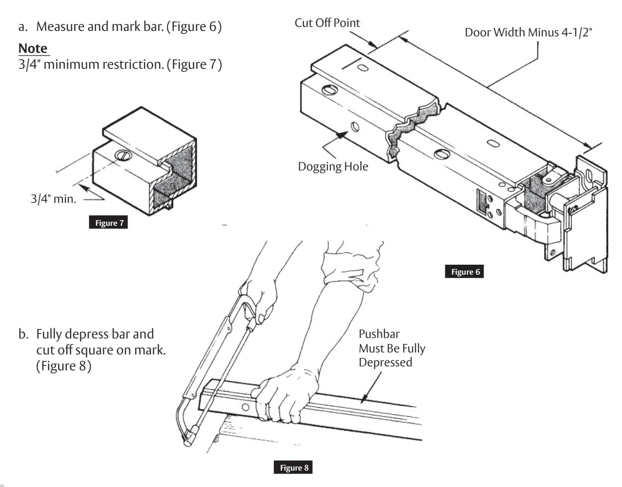
d Mount Device
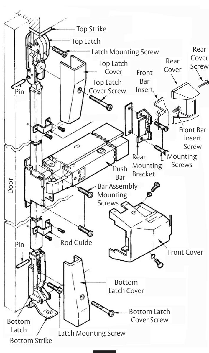
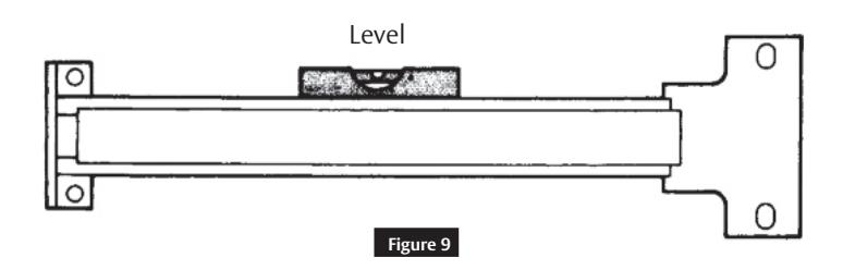
Attach bar assembly to door, but do not tighten screws. Assemble rear mounting bracket to push bar (see nesting arrangement in exploded view in Figure 2). Use rear mounting bracket as a template to spot holes for mounting screws. Push bar should be level. Drill screw holes and attach rear mounting bracket and plate to door. Secure front plate screws.
7

3
Installation (cont.)
e
Install Strikes
Close door. Align center of strike with vertical backset centerline on door and install top and bottom strikes.
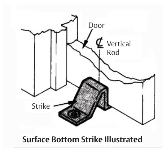
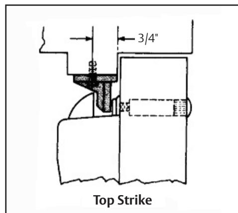
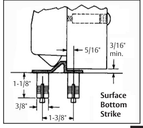
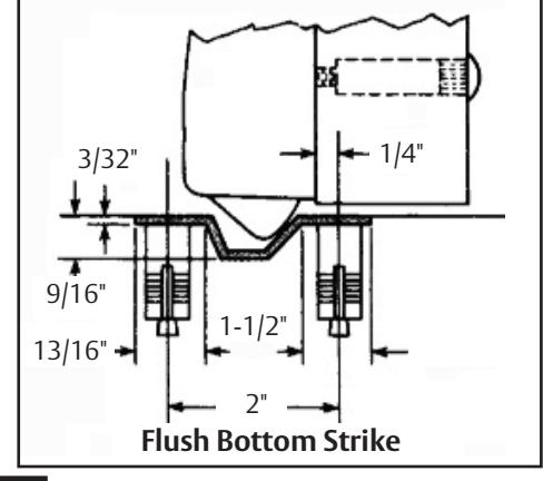
Figure 10
Vertical Rod Exit Devices
Installation Instructions

3 Installation (cont.)
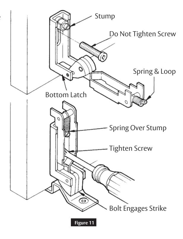
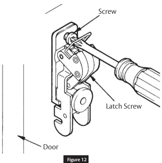
f Mount Bottom Latch
Insert bottom latch screw through slot in latch frame into bottom hole. Do not tighten. Lift up slide assembly and fit the spring loop over the stump on the latch frame. Position latch frame so that latch engages strike. Now tighten bottom screw. Drill a hole for the cover screw, using the hole in the slide assembly at top as guide. Spot with 1/4" drill. Drill through with #3 drill for self-tapping screw.
g Mount Top Latch
Retract the latch by pushing up on slide and fasten latch assembly with screws as illustrated. Be sure to draw the screw up tight. Drill hole for the cover screw, using the hole in the slide assembly at bottom as guide.

3 Installation (cont.)
h Top Rod Assembly
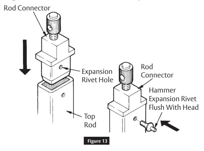
Measure distance from bottom screw hole of top latch case to top screw hole in active case. Cut undrilled end of top rod to this length minus 1". (Figure 2) Seat adjustable rod connector in cut end of rod. Using hole as a guide, drill through connector and rod. Secure with expansion rivet from front of rod.
i Install Top Rod and Adjust Top Latch
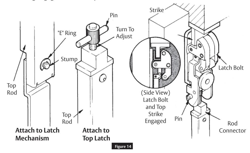
Attach top rod to bar assembly by slipping hole over stump and secure rod by means of "E" ring. Shut door. Turn adjustable rod connector until head touches underside of latch slide. Insert pin. Depress bar. If top latch does not retract completely, remove pin and turn connector to adjust length. Repeat until latch bolt just disengages.
Caution
Make certain "E" ring engages slot in stump.
Vertical Rod Exit Devices
Installation Instructions

3 Installation (cont.)
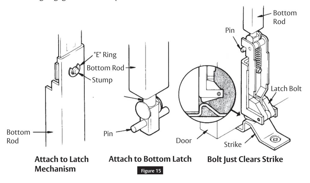
j Install and Adjust Bottom Rod
Attach bottom rod to bar assembly by slipping hole over stump and secure rod by means of "E" ring. Shut door. Dog down active case. Insert pin into rod connector. Turn adjustable rod connector by turning clockwise or counter clockwise until latch bolt just clears strike. Undog device.
Caution
Make certain "E" ring engages slot in stump.
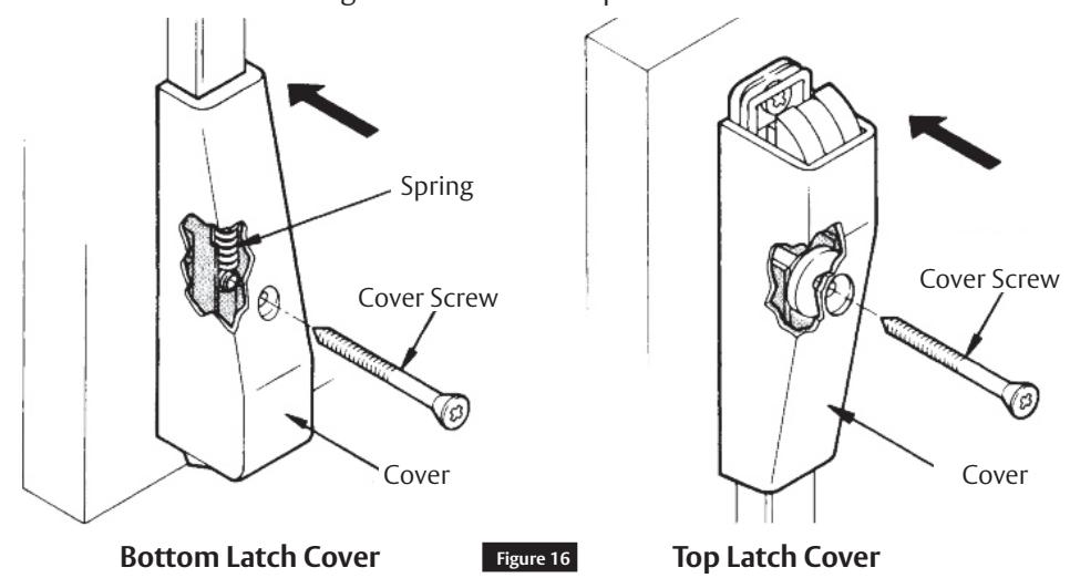
k Mount Top and Bottom Latch Covers
Bottom Cover
Position above bottom latch frame and align with hole in slide assembly at bottom. Secure with furnished screw.
Top Cover
Position and secure with screw through bottom hole in top latch frame.

3 Installation (cont.)
l Test Pushbar and Dogging Operations
The latches should engage the strikes when the door is closed. If the door can be pushed open without depressing the push bar, the top rod connector has been over adjusted. Remove cover and adjust connector as needed. Replace cover when finished.
The top and bottom latches should disengage from the strikes freely when the pushbar is depressed or dogged down. If they do not disengage, remove the covers and adjust the connectors as needed. Replace the covers. Retest for proper operation.
Device only
Top and bottom latch bolts are retracted by the pushbar inside.
Device with trim
Top and bottom latch bolts are retracted by the push bar inside and the key or knob outside.
To Lock Knob
Insert key in cylinder and turn counter clockwise as far as key will turn. Then return key to its vertical position and withdraw key.
To Unlock Knob
Insert key in cylinder and turn clockwise as far as key will turn (the latches will retract during this procedure). Then return key to its vertical position and withdraw key.
Dogging
Depress pushbar. Insert dogging wrench and turn clockwise 90 ˚ . The push bar will remain depressed and the latches will remain retracted.
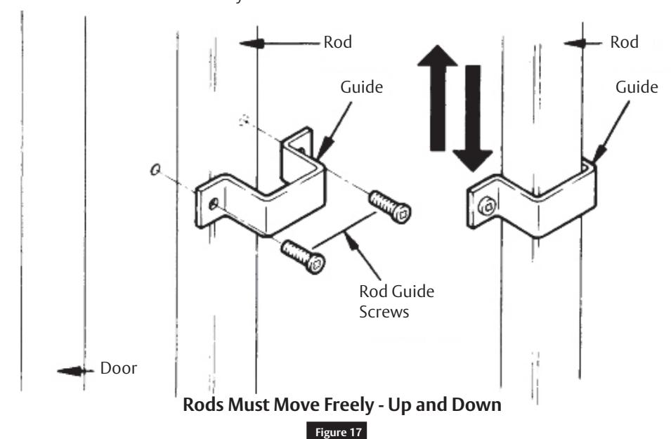
m Mount Rod Guides
Place guides over the rod. (One above the bar assembly and one below the bar.) Be sure the guides will not bind against the rods. Use holes in the guides to spot screw location. Drill holes and secure the guides to the door.
Check to be certain the rods move freely.

4 Remove and Reinstall Cylinder In Knob
Remove Knob:
- 1. Insert key in cylinder and turn 90° clockwise.
- 2. Insert knob removing tool into the hole in the knob and depress the knob catch button.
- 3. While knob catch button is depressed, pull knob off.
Remove Cylinder From Knob:
- 1. Remove sleeve.
- 2. Remove key.
- 3. Slide cylinder out of knob.
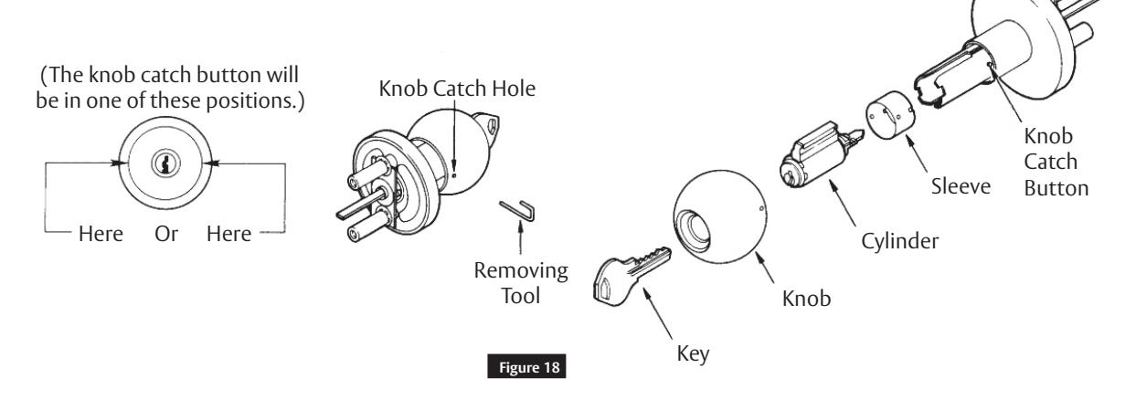
Reinstall Cylinder in Knob:
- 1. Slide cylinder into knob.
- 2. Replace sleeve.
Reinstall Knob
- 1. With key inserted part way into cylinder slide knob onto knob shank.
- 2. Depress knob catch button and push knob onto the knob shank as far as it will go.
- 3. Insert key completely into the cylinder and turn key while pushing on the knob until it engages the knob catch button.
- 4. Return key to its vertical position and remove it.
- 5. Pull on the knob to be certain it is properly engaged to the knob catch button.
ED8400 Series
Vertical Rod Exit Devices
Installation Instructions

Page intentionally left blank.
ED8400 Series
Vertical Rod Exit Devices
Installation Instructions

Page intentionally left blank.

Corbin Russwin, Inc. 225 Episcopal Road Berlin, CT 06037 USA Phone: 800-543-3558 Fax: 800-447-6714 www.corbinrusswin.com
ASSA ABLOY is the global leader in door opening solutions, dedicated to satisfying end-users needs for security, safety, and convenience