Corbin Russwin ED8000 Series ED8200 Wide Stile Low Profile Rim Installation Instructions_FM37
Open the original PDF document
View PDFInstallation Instructions


This product can expose you to lead which is known to the state of California to cause cancer and birth defects or other reproductive harm. For more information go to www.P65warnings.ca.gov.
ED8200 Series
Low Profile Rim Exit Devices - Reversible
Installation Instructions

| TOC | Table of Contents | |
|---|---|---|
| 1 | Wood and Metal Door Prep2 | |
| 2 |
Spot and Drill Template Holes
3 |
|
| 3 | Insert Trim and Strike3 | |
| 4 | Cutting Push Bar5 | |
| 5 | Mount Device5 | |
| 6 | Test Push Bar and Dogging Operation6 | |
| 7 | Remove and Reinstall Cylinder in Knob6 | |
| 8 | Template7 |
1 Wood and Metal Door Prep
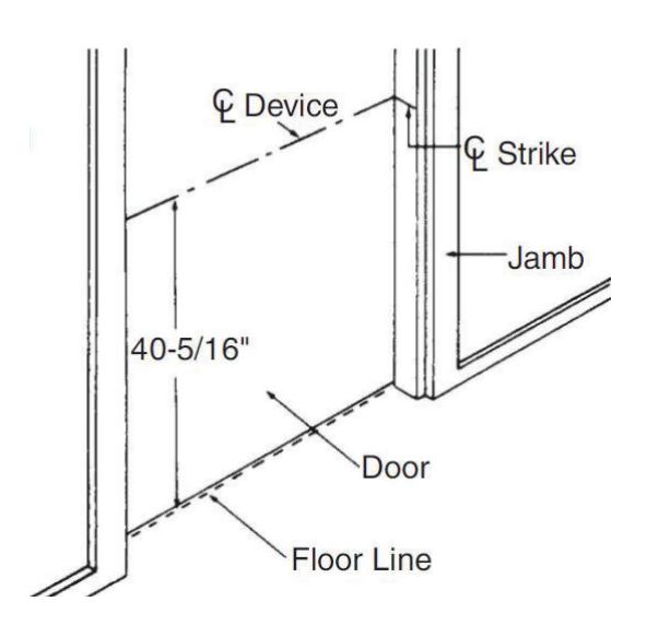
a Mark Centerline
Establish the centerline of the device by drawing a line across the door and stop 40-5/16" above the floor.
Installation Instructions

1 Wood and Metal Door Prep
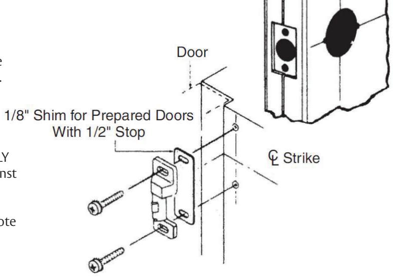
b If your door has cylindrical lock cut-out for ANSI A115.2 and A115.3 Prep Doors (Not for use with mullions.)
1. Extend horizontal and vertical centerlines of cut out as shown at right.
2. If frame has 5/8" stop, align centerlines on template with centerlines on door. Spot and drill template holes as described above and follow steps three through six.
3. If frame has 1/2" stop, align centerlines on template with centerlines on door and spot mounting hols for LATCH ASSEMBLY ONLY. The MOVE template up against stop and spot mounting holes for strike. Drill two mounting holes. Now follow steps three thru six. Note special shim shown at right, which is mounted beneath strike. Shim furnished only when ordered.
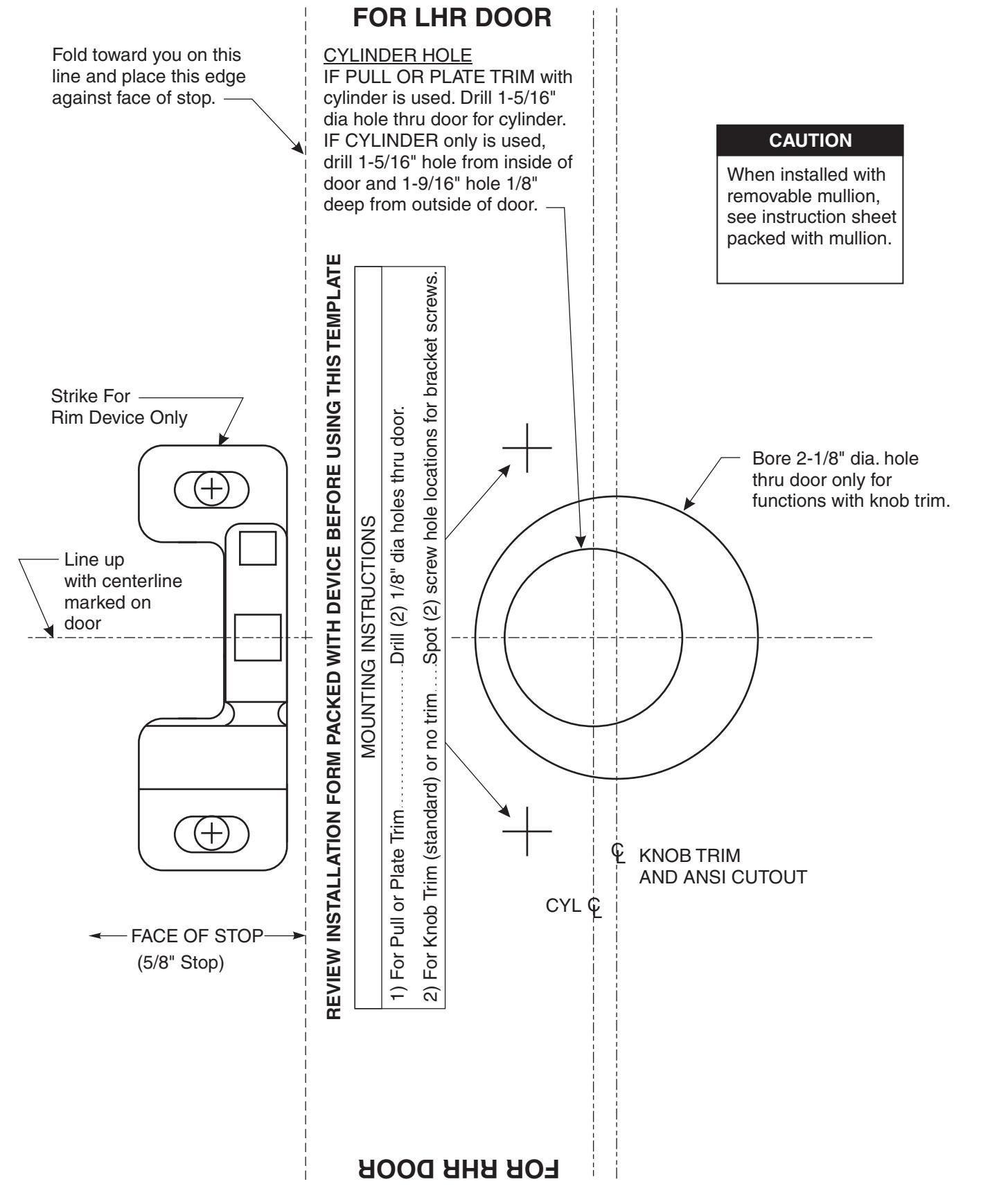
2 Spot and Drill Template Holes
Using template furnished, spot and drill mounting holes for trim (if furnished), device, and strike.
Caution: When installed with removable mullion, see instruction sheet packed with mullion. (Not for use with ANSI prep.)
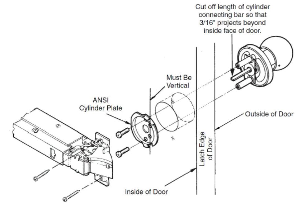
3 Install Trim and Strike
a Knob Trim
Caution: Refer to template packed with trim before proceding with Step 3.
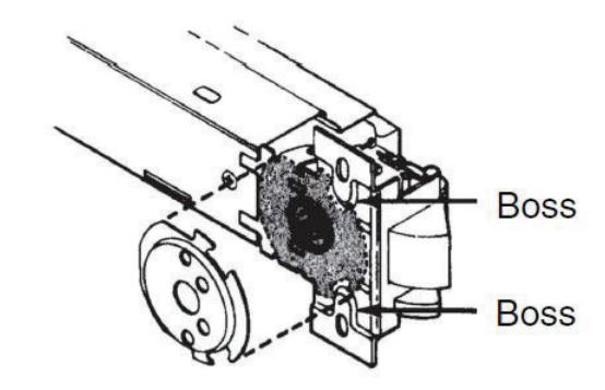
Caution: When using the ANSI cylinder plate, the bosses on the latch assembly must fit into the cutouts on the cylinder plate so that the latch assembly lays flat on the door.
Installation Instructions

3 Install Trim and Strike, continued
a Knob Trim, continued
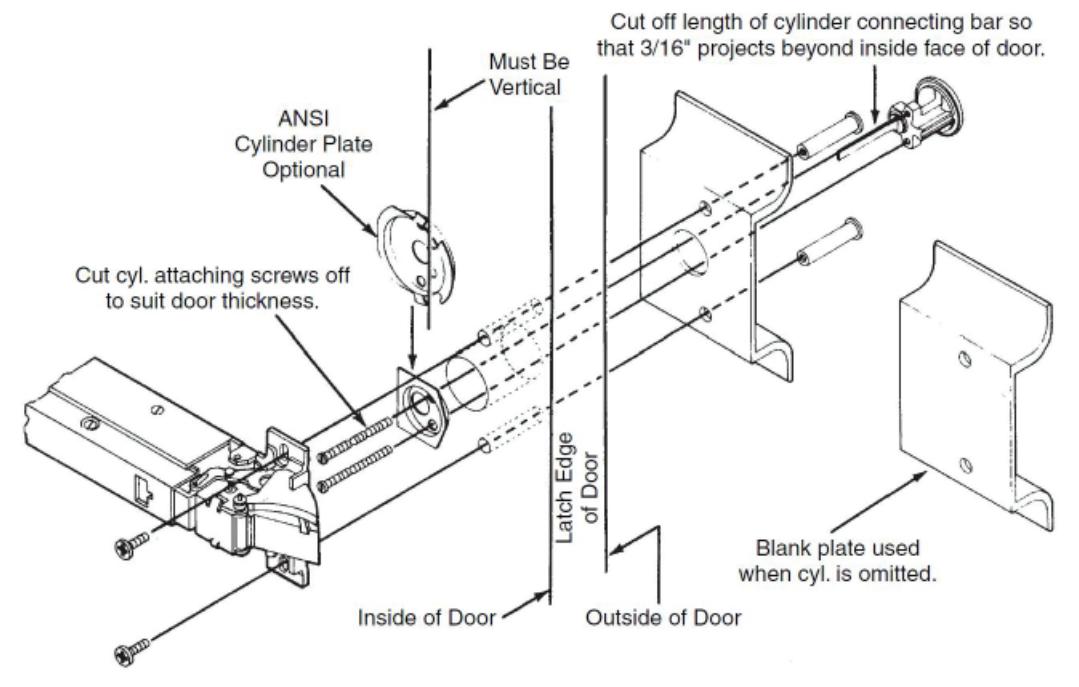
b Pull and Plate Trim
Caution: Refer to template packed with trim before proceding with Step 3.
Caution: When using the ANSI cylinder plate, the bosses on the latch assembly must fit into the cutouts on the cylinder plate so that the latch assembly lays flat on the door.
Installation Instructions

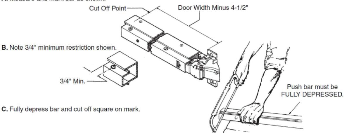
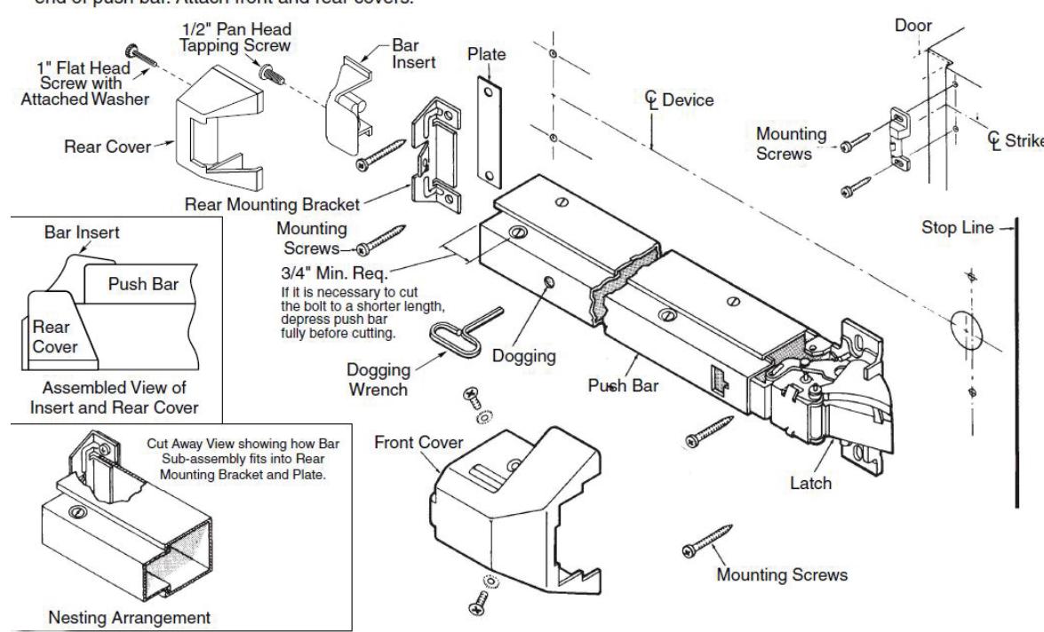
4 Cutting Push bar
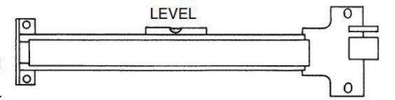
5 Mount device
Installation Instructions

6 Test Push Bar and Dogging Operation
No-Trim Series:
Latch bolt is retracted by the push bar inside.
Pull and Plate Trim Series:
Latch bolt is retracted by the push bar inside and the key outside. Turning the key in either direction will retract the latch. Return key to the horizontal position to remove key and project latch.
Knob Trim Series:
Latch bolt is retracted by the push bar inside and the key or knob outside.
To lock knob: Insert key in cylinder and turn counterclockwise as far as the key will turn. Then return it to its vertical position and withdraw key.
To unlock knob: Insert key in cylinder and turn clockwise as far as the key will turn (the latch will retract during this procedure). Then return the key to its vertical position and withdraw key.
Dogging: Depress push bar. Insert dogging wrench and turn clockwise 90°. The push bar will remain depressed and the latch will remain retracted.
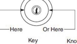
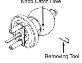
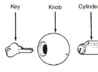
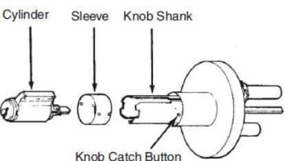
7 To Remove and Reinstall Cylinder in Knob

| Screw Chart | ||||
|---|---|---|---|---|
| Item | Qty. | Fastener | ||
|
Front plate
assembly and rear bracket |
4 |
12-24 x 3/4 Lg. pan head machine screw
or #12 x 1-1/4 Lg. pan head tapping screws type "A" |
||
| Strike | 2 |
12-24 x 3/4 Lg. pan head machine screw
or #12 x 1-1/4 Lg. pan head tapping screws type "A" |
||
Installation Instructions


Corbin Russwin, Inc. 225 Episcopal Road Berlin, CT 06037 USA Phone: 800-543-3558 Fax: 800-447-6714 www.corbinrusswin.com