Corbin Russwin ED8000 Series ED8200, ED8200B Wide Stile Rim Installation Instructions_FM17
Open the original PDF document
View PDFInstallation Instructions

ED8200 Series
Panic Listed
ED8200B Series
1-1/2 Hour Fire Rated

Exit Device
Attention Installer:
Failure to follow these instructions could affect operation of this product and void warranty.
Some trim designs are handed when used with this device (see trim instructions).
Exit devices must be securely fastened to properly reinforced doors with fasteners which will not loosen or pull out. Add reinforcement when necessary.
Before installing: Be sure exit device is the proper hand for your door.
Use enclosed template to assure proper operation.

This product can expose you to lead which is known to the state of California to cause cancer and birth defects or other reproductive harm. For more information go to www.P65warnings.ca.gov.
ED8200 and ED8200B Series
Pushbar Exit Device
Installation Instructions

1 General Information
Push Side How To Determine Hand of Door Dogging (8200 Only):
Left Hand Reverse LHR Pull Side Right Hand Reverse RHR
Feature to hold bolts retracted and touchpad depressed for push-pull door operation.
To Dog Device:
- Insert dogging key.
- Hold touchbar depressed.
- Turn key 1/4 turn clockwise.
Not a feature on fire rated devices.
ED8200 ED8200B
| Latch Assembly | 2 | 2 |
#12-24 x 3/4" Phillips Pan Head Machine Screws, #12 Internal Washers
(Wood doors: #12 x 1-1/4" Phillips Pan Head, Type A, Tapping Screws) |
|---|---|---|---|
| Rear Bracket | 2 | 2 |
#12-24 x 3/4" Phillips Pan Head Machine Screws, #12 Internal Washers
(Wood doors: #12 x 1-1/4" Phillips Pan Head, Type A, Tapping Screws) |
| Strike | 2 | 2 |
#12-24 x 3/4" Phillips Pan Head Machine Screws, #12 Internal Washers
(Wood doors: #12 x 1-1/4" Phillips Pan Head, Type A, Tapping Screws) |
| Front Bar Insert | 1 | 1 | #8-32 x 1" Phillips Pan Head Machine Screw |
| Rear Cover | 1 | 1 | #8-32 x 1" Phillips Flat Head Machine Screw with External Washer |
| Front Cover | 2 | 2 | #8-32 x 1/2" Phillips Flat Head Machine Screw, Type F, with External Washers |
| Non-Reinforced Door | - | 4 | #12-24 x 1-21/32" Sex Nuts |
| Dogging Wrench | 1 | N/A | 3/16" Hex |
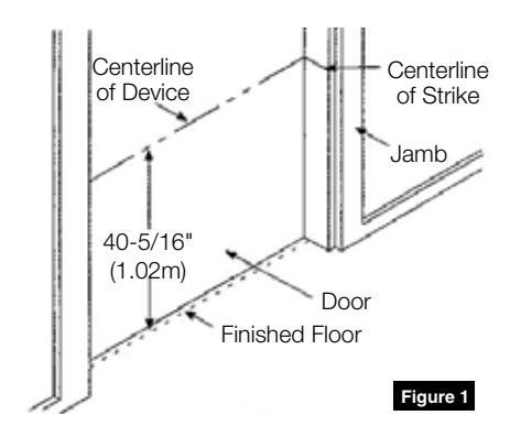
2 Mark Door
1. Establish horizontal centerline of device by drawing line across door and stop, 40-5/16" (1.02m) above finished floor unless doors have been pre-prepped. (Figure 1)
3 Install Trim, if furnished
See enclosed trim installation instructions.
ED8200 and ED8200B Series
Pushbar Exit Device
Installation Instructions

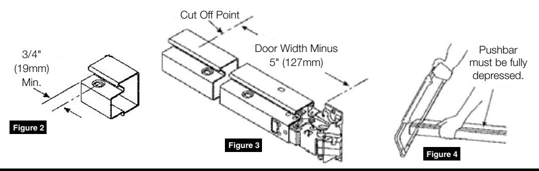
4 Cut Pushbar, if required
NOTE: If bar does not require cutting, proceed to Section 5.
- 1. Installation of device depends on trim. Note 3/4" (19mm) minimum restriction. (Figure 2)
- 2. Measure and mark bar as shown. (Figure 3)
- 3. Fully depress bar and cut off square on mark. (Figure 4)
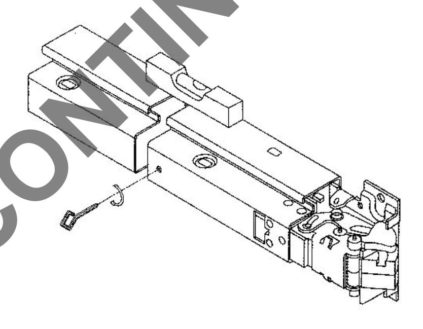
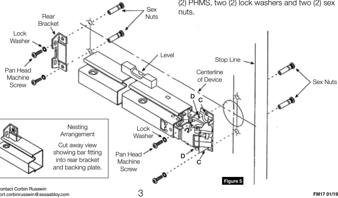
5 Mount ED8200 or ED8200B Exit Device
Installation of device depends on trim. (Figure 5)
1. For Through-bolted Trim In 2-1/8" Prep Install device with two (2) fillister head screws (packed with trim) in latch assembly holes marked D.
For All Other Applications
Install device with two (2) PHMS, two (2) internal tooth lock washers and two (2) sex nuts in latch assembly holes marked C.
2. For Reinforced Metal Doors
Ensure device is level. Use rear bracket to spot, drill and tap two (2) #12-24 rear bracket mounting holes. Attach rear bracket to door using two (2) PHMS and two (2) lock washers.
For All Other Door Types
Ensure device is level. Use rear bracket to spot and drill 1/4" (6mm) holes through door. Enlarge holes 3/8" (10mm) from opposite side of door to clear for sex nuts and bolts. Attach rear bracket and backing plate to door using two (2) PHMS, two (2) lock washers and two (2) sex
For installation assistance contact Corbin Russwin 1-800-543-3658 • techsupport.corbinrusswin@assaabloy.com

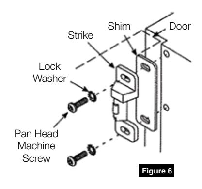
5 Install Strike
- 1. Install strike with two (2) pan head machine screws, two (2) external tooth lock washers. (Figure 6)
- 2. Adjust strike.
NOTE: Strike is properly adjusted when latch is able to fully project when door is closed.
3. Tighten all screws.
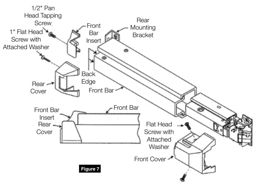
6 Install Front Bar Insert, Rear and Front Covers
- 1. Slide front bar insert over end of front bar.
- 2. Insert 1/2" pan head tapping screw through insert mounting hole.
- 3. While holding insert flush against back edge of front bar, tighten screw to bottom of recessed mounting hole.
- 4. Install front and rear cover using 1" flat head screw with attached washer.
(Figure 7)
7 Test Pushbar
Latchbolt is retracted by pushbar inside. If latchbolt does not operate properly or does not remain secure, inspect all mounting dimensions outlined is Sections 3-5.
Corbin Russwin 225 Episcopal Road Berlin, CT 06037 Phone: 800-543-3658 Fax: 800-447-6714 corbinrusswin.com