Corbin Russwin ED7400 Series Surface Vertical Rod Installation Instructions
Open the original PDF document
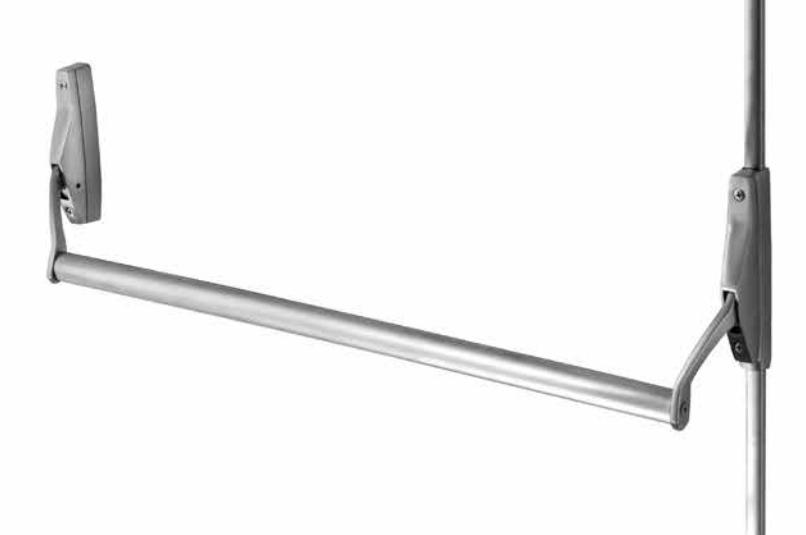
View PDFInstallation Instructions


Surface Vertical Rod
Exit Devices

This product can expose you to lead which is known to the state of California to cause cancer and birth defects or other reproductive harm. For more information go to www. P65warnings.ca.gov.
For installation assistance contact Corbin Russwin 1-800-543-3658 • techsupport.corbinrusswin@assaabloy.com
(617415000) FM463 10/18
Installation Instructions

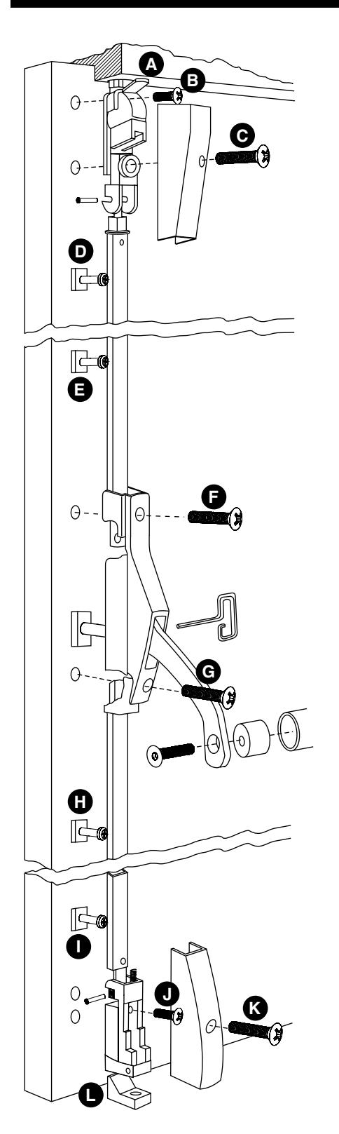
1 Screw Guide
| Screw Guide | ||
| Screw | Wood Door | Metal Door |
| A |
Top Strike
#12 Round Head WS |
#12-24 Pan Head Machine
Screws |
| B |
1/4-20 Binding Head Machine Screw and 7/16"
Sex Nut |
|
| C | 1/4-20 Oval Head Mach Screw and 7/16" Sex Nut | |
| D | #12 Round Head WS |
#12 Round Head Tapping
Screw (Use 5/32" drill) |
| E | #12 Round Head WS |
#12 Round Head Tapping
Screw (Use 5/32" drill) |
| F | 1/4-20 Oval Head Mach Screw and 7/16" Sex Nut* | |
| G | 1/4-20 Oval Head Mach Screw and 7/16" Sex Nut* | |
| H | #12 Round Head WS |
#12 Round Head Tapping
Screw (Use 5/32" drill) |
| I | #12 Round Head WS |
#12 Round Head Tapping
Screw (Use 5/32" drill) |
| J |
1/4-20 Binding Head Machine Screw and 7/16"
Sex Nut |
|
| K | #14 Oval Head WS |
1/4-20 Oval Head Self
Tapping (Use #3 drill) |
| L |
Surface Bottom
Strike #14 Flat Head WS |
1/4-20 Flat Head Mach
Screws x 3415 Star Anchor or equiv. |
| M |
Flush Bottom Strike
#14 Flat Head WS |
1/4-20 Flat Head Mach
Screws x 3415 Star Anchor or equiv. |
* Sex Nut not required if outside trim used.
Figure 1
Installation Instructions

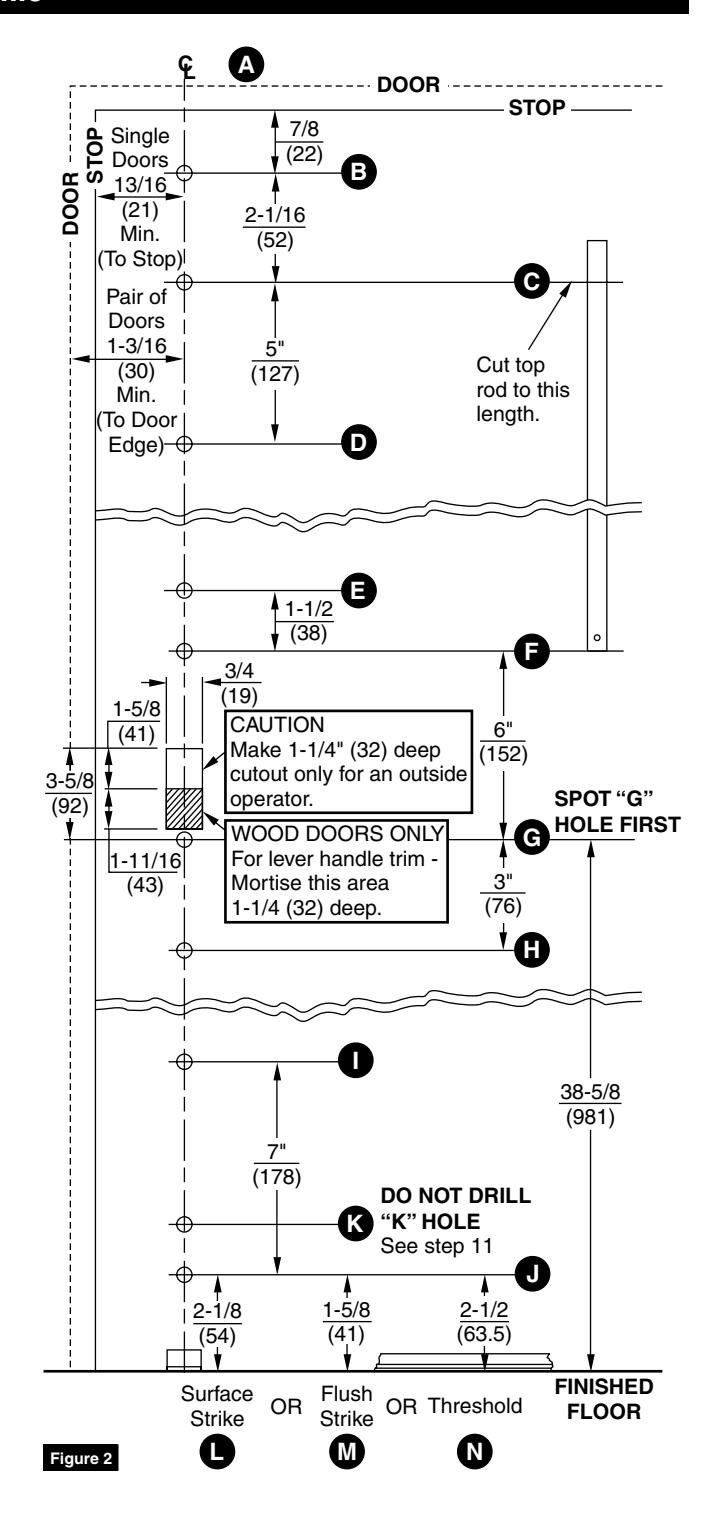
2 Locate All Inside Holes On Centerline
1. Spot and drill holes B to J for screws and sex nuts (as listed in screw guide - Figure 1 on page 2). (Figure 2) SPOT G FIRST.
NOTE: 13/16" (21mm) minimum distance between stop and centerline with single doors. With pair of doors, 1-3/16" (30) minimum centerline to edge of door.
NOTE: If you have outside operator and trim, use case mounting holes F and G to locate trim template.
Installation Instructions

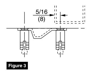
3 Mount Top and Bottom Strikes
Using centerline established on door, close door and mount strikes against door.
NOTE: Except for flush bottom strike. See drawing for position. (Figure 3)
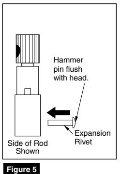
4 Cut and Assemble Top Rod
- 1. Measure distance from bottom screw hole "C" of top latch case to top screw hole "F" in active case. (Figure 2 on page 3)
- 2. Cut undrilled end of top rod to this length.
- 3. Seat adjustable rod connector as shown in cut end of rod. (Figure 4)
- 4. Using hole as guide, drill through connector and rod.
- 5. Secure with expansion rivet from front of rod. (Figure 5)

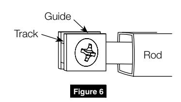
5 Insert Rod Guides - Position Top Rod
- 1. Install 4 top and bottom rod guides exactly on centerline. (D, E, H, I; Figure 2 on page 3)
- 2. Seat screw but do not crush guide.
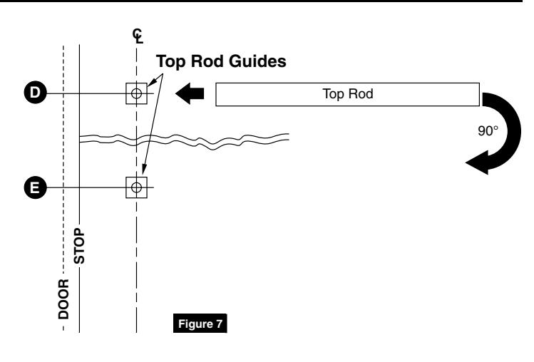
- 3. Rotate guide "D" so track is horizontal. (Figure 6)
- 4. Slip top rod over guide and rotate to vertical position, sliding rod down over guide "E". (Figure 7)
Installation Instructions

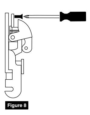
6 Mount Top Latch Frame
Retract latch and secure case with screw "B". (Figure 8)
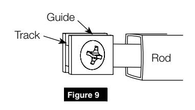
7 Mount Bottom Rod
- 1. Turn guide "I" so track is horizontal. (Figure 9)
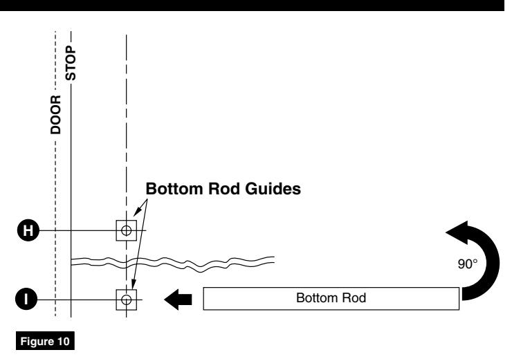
- 2. Slip bottom rod over guide and rotate to vertical position, sliding rod up over guide "H". (Figure 10)
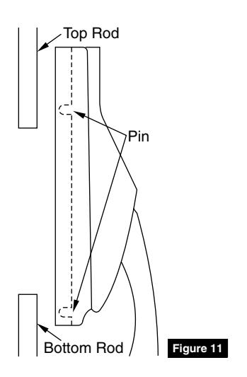
8 Mount Active Case and Attach Rods
- 1. Position case so that pins in back engage holes in top and bottom rods. (Figure 11)
- 2. Secure with screws F and G. (Figure 1 on page 2)
NOTE: If you have outside trim follow template furnished.
TO REVERSE HAND:
- 1. Remove two (2) screws from back of each case to separate bodies from covers.
- 2. Switch covers and reassemble.
Installation Instructions

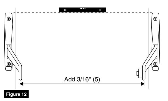
9 Mount Inactive Case and Crossbar
- 1. Mount inactive case level with active case.
- 2. Measure distance between bottom of levers and add 3/16" (5mm). (Figure 12)
- 3. Cut crossbar to this length. Remove burrs.
- 4. Remove tenon from active case lever and insert in cross bar so it is flush with end.
- 5. Place open end of crossbar over tenon on inactive case lever. (Loosening screw slightly will make easier fit.) Tap screw with mallet if necessary.
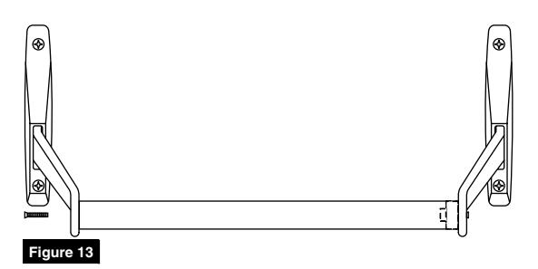
- 6. Position other end of crossbar in recess in active case lever. Insert screw through lever into tenon. Finger tighten. (Figure 13)
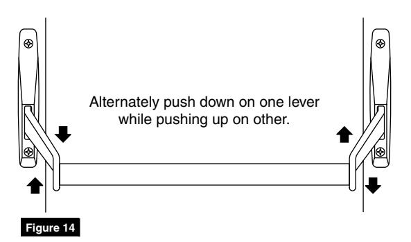
- 7. Seat bar in levers by rocking crossbar to seat tenon pins. (Figure 14)
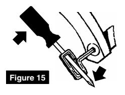
NOTE: Tightly secure screws using screwdriver through bow of dogging key. (Figure 15)
NOTE: If levers do not work freely, check for binding of levers due to improper bar length or case misalignment.
Corbin Russwin is a brand associated with ASSA ABLOY Access and Egress Hardware Group, Inc., an ASSA ABLOY Group company. Copyright © 2018, ASSA ABLOY Access and Egress Hardware Group, Inc. All rights reserved. Reproduction in whole or in part without
the express written permission of ASSA ABLOY Access and Egress Hardware Group, Inc. is prohibited.
Installation Instructions

10
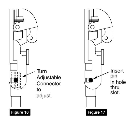
Adjust Top Latch
- 1. Shut door.
- 2. Turn adjustable rod connector until head touches underside of slide. (Figure 16)
- 3. Insert pin. (Figure 17)
- 4. Depress crossbar.
- 5. If latch does not retract completely, remove pin and turn connector out one (1) turn.
- 6. Repeat until latch bolt just disengages.
NOTE: For maximum security, do not over-adjust.
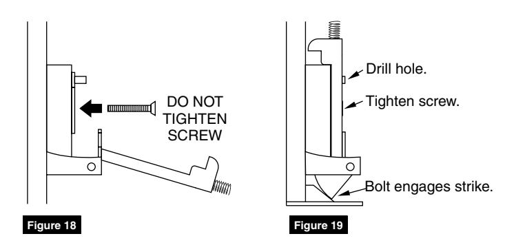
11
Mount Bottom Latch Frame
- Insert screw "J" through slot in frame into bottom hole. (Figure 18)
- 2. Position frame so that latch just engages strike. (Figure 19)
- 3. Tighten bottom screw.
- 4. Using hole "K" in frame as a guide, drill door through hole in frame.
- 5. Insert screw "K".
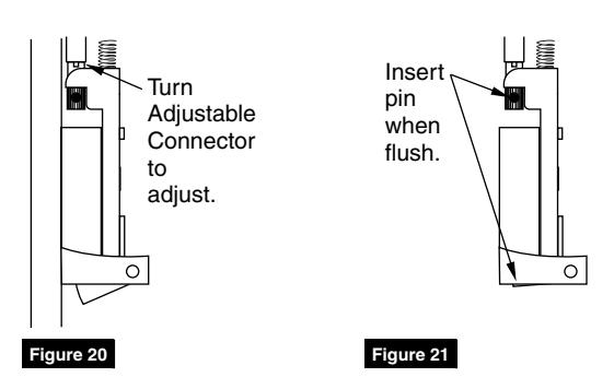
12
Adjust Bottom Rod Length and Engage Latch
- 1. Dog down active case.
- 2. Turn adjustable rod connector so that latch bolt is flush with bottom of frame. (Figure 20)
- 3. Insert pin in adjustable rod connector. (Figure 21)
- 4. Undog active case.

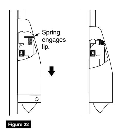
13 Mount Latch Covers
Bottom
- 1. Position bottom latch cover above bottom latch frame and slide down to engage spring. (Figure 22)
- 2. Secure with furnished screw.
Top
1. Position and secure with screw through bottom hole in frame.
14 Test Operation
Latches should tightly engage strikes in closed position.
If door can be pushed open without depressing crossbar, top rod connector has been over-adjusted. See Step 10.
When crossbar is depressed, latches should freely disengage strikes.
When active and inactive cases are dogged down, latches should disengage strikes.
If not, remove top and bottom latch cases and readjust adjustable rod connectors. See Steps 10 and 12.
Corbin Russwin 225 Episcopal Road Berlin, CT 06037 Phone: 800-543-3658 Fax: 800-447-6714 corbinrusswin.com
ASSA ABLOY is the global leader in door opening solutions, dedicated to satisfying end-user needs for security, safety and convenience