Corbin Russwin ED7000 Series ED7800 Narrow Stile CVR Installation Instructions_FM466
Open the original PDF document
View PDFInstallation Instructions

ED7800 Series
Concealed Vertical Rod Exit Device

This product can expose you to lead which is known to the state of California to cause cancer and birth defects or other reproductive harm. For more information go to www. P65warnings.ca.gov.
For installation assistance contact Corbin Russwin 1-800-543-3658 • techsupport.corbinrusswin@assaabloy.com
Copyright © 2018, 2023, ASSA ABLOY Access and Egress Hardware Group, Inc. All rights reserved. Reproduction in whole or in part without the express written permission of ASSA ABLOY Access and Egress Hardware Group, Inc. is prohibited.
WARNING
Attention Installer: Improper installation may result in damage to the product and void the factory warranty.
Concealed Vertical Rod Exit Device
Installation Instructions
ASSA ABLOY

Components
| Screws Furnished | ||||
|---|---|---|---|---|
| Screw Thread | Tap Drill | Placement | ||
| 10-32 | No. 21 |
Bottom and Top Mounting Brackets
(Concealed Bracket Mounting) Top Latch and Bottom Bolt Cases (Exposed Screw Mounting) |
||
| 8-32 | No. 29 | Top Strike | ||
| 1/4-20 | No. 7 | Active and Inactive Cases | ||
| 1/4-20 & Anchor | Bottom Strike | |||
|
Tap
Drill |
%
Thread |
|||
| 10-24 Self- | 18 | 75% | ||
| Tapping | 11/64 | 70% | Outside Operator | |
| 17 | 65% | |||
| 16 | 55% | |||
Figure 1
For installation assistance contact Corbin Russwin 1-800-543-3658 • techsupport.corbinrusswin@assaabloy.com
Reproduction in whole or in part without the express written permission of ASSA\ ABLOY\ Access and\ Egress\ Hardware\ Group, Inc.\ is\ prohibited.
Experience a safer and more open world
2
Concealed Vertical Rod Exit Device
Installation Instructions


2 Pre-Installation
Important
4061, 4062, 4063, 4068, CH641, CH642, CH643, CH648 "U" indicates UL Listed and "MR" indicates Master Ring Cylinder
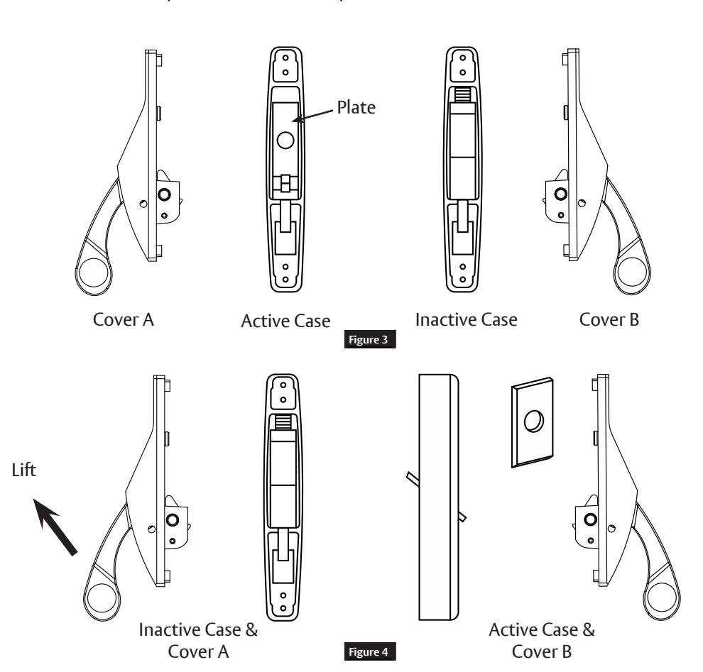
Before installing, check position of parts for hand of door and reverse hand of fi xture if necessary.
- 1. To change to opposite hand, hammer pin to opposite side of fl ange. (Figure 3)
- 2. Remove case covers by removing top and bottom screw at back of each case.
-
3. Switch case covers and reassemble.
- a. Place cover from present active case (A) on inactive case, engaging lifting fi nger with bottom of slide. (Figure 4)
- b. Place cover from inactive case (B) on active case, engaging lifting fi nger with bottom of slide. Be sure that nylon button on back of cover fi ts into hole in plate. (Figure 5)
NOTE: Be sure that plate with hole in it is positioned in active case with rounded end down.
Concealed Vertical Rod Exit Device
Installation Instructions

3 Prepare Door and Frame
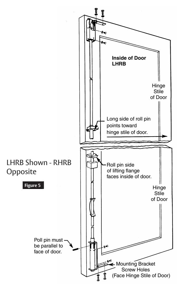
If not already fully prepared, follow template furnished and drawings shown for exposed screw or hidden (bracket) mounting. See Figure 6.
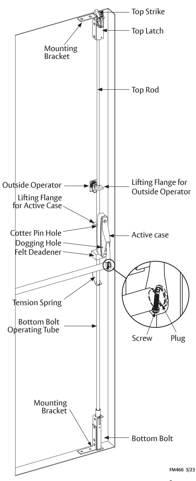
4 Insert Rods and Secure Top Latches and Bottom Bolt
NOTE: See exposed screw or hidden (bracket) mounting illustrations. (Figure 6)
Before inserting, check for proper positioning of all parts.
1. If using CONCEALED (bracket) MOUNTING, attach mounting brackets to cases of top latch and bottom bolt NOW.
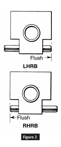
- 2. Slide bottom tube into bottom of stile. Secure with screws indicated in chart. (Figure 2 on page 2)
- 3. Retract top latch by holding case and pushing up on rod. Insert top latch rod into top of stile and into bottom tube. Secure with screws indicated in chart. (Figure 2 on page 2)
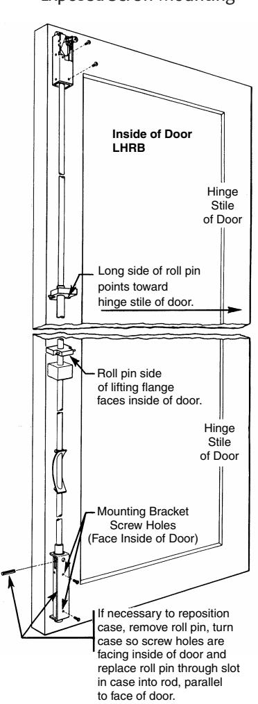
Exposed Screw Mounting Concealed Screw (Bracket) Mounting
Concealed Vertical Rod Exit Device
Installation Instructions
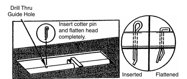
5 Pin Top Rod and Bottom Tube
- 1. Using access hole, raise lifting fl ange for active case so that bottom bolt is fully retracted. DO NOT PRESS BOTTOM BOLT FROM BOTTOM OF DOOR. Be sure that top latch is retracted.
- 2. Drill 1/8" diameter hole through rod and tube using predrilled hole in bottom tube as guide. (Figure 7)
- 3. Insert hammer-lock cotter pin through hole and secure with punch and hammer. Flatten pin head completely. (Figure 7) Hang door.

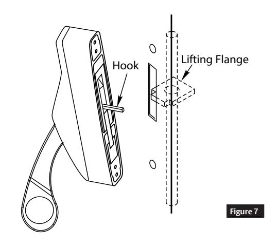
6 Install Active Case
- 1. Undog cases. Using key furnished, back out screw and remove tenon from active case lever. (Figure 1 on page 2)
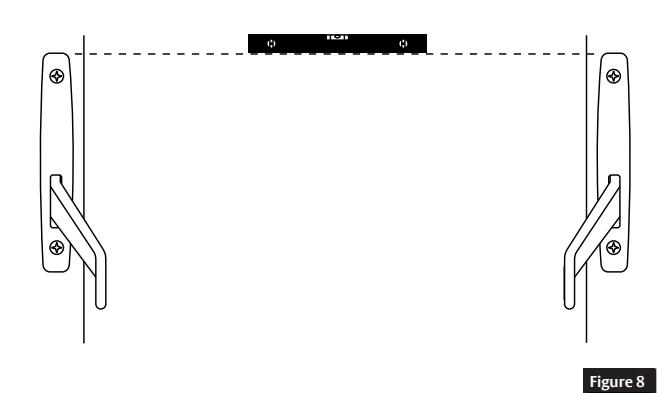
- 2. Mount active case, engaging hook under lifting fl ange. Secure with screws furnished. (Figure 8)
7 Test Operation
- 1. Push down on active case lever to be sure top latch and bottom bolt retract completely and remain retracted when lever is released.
- 2. If bottom bolt does not retract fl ush with bottom of door, check "Pin Top Rod and Bottom Tube" procedure.
8 Install Inactive Case
- 1. Place case in position. Be sure cases are level at same height. (Figure 9)
- 2. Drill and tap for No. 1/4-20 screws.
- 3. Mount cases.
Concealed Vertical Rod Exit Device
Installation Instructions
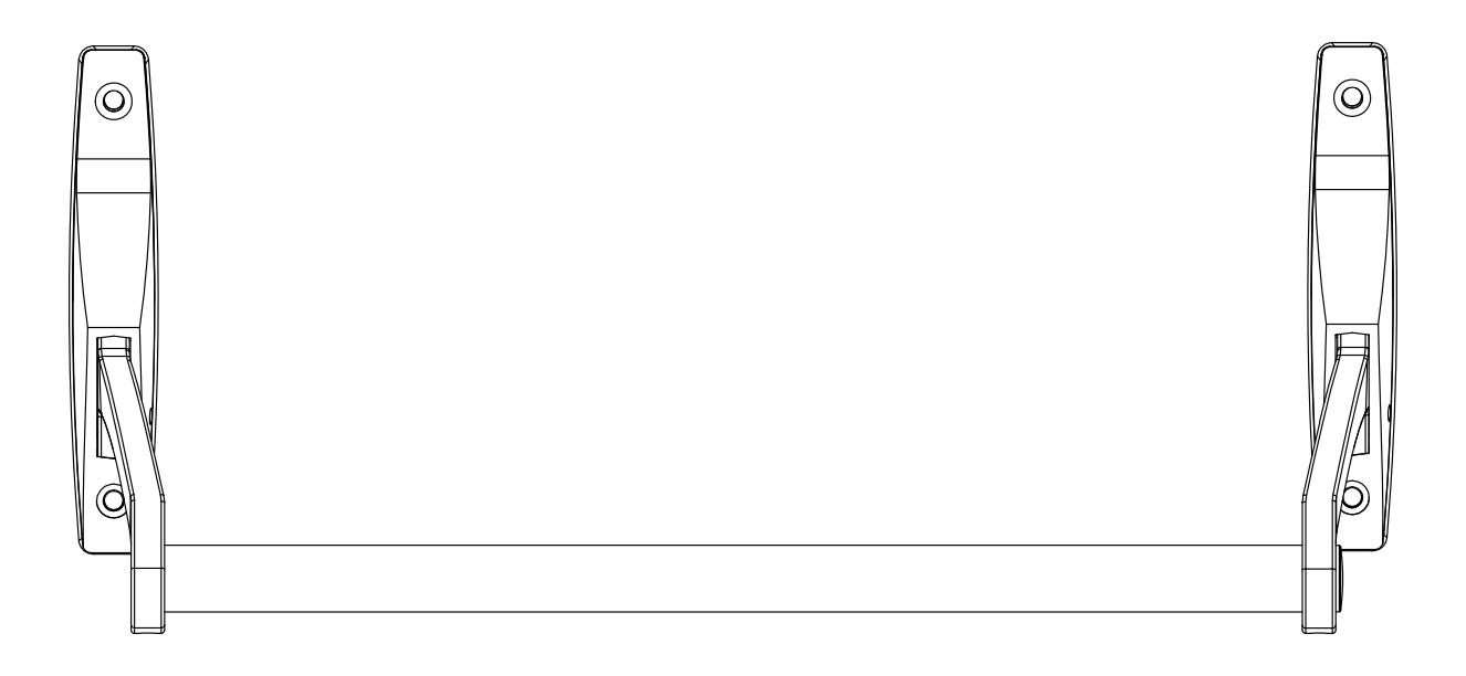
9 Install Crossbar
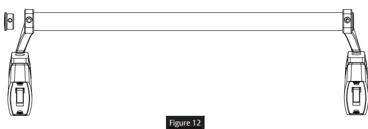
- 1. Slide bar through active and inactive case with screw hole towards active case. Screw plug and bar onto active case with 10- 24 x 3/4" cap screw. (Figure 10)
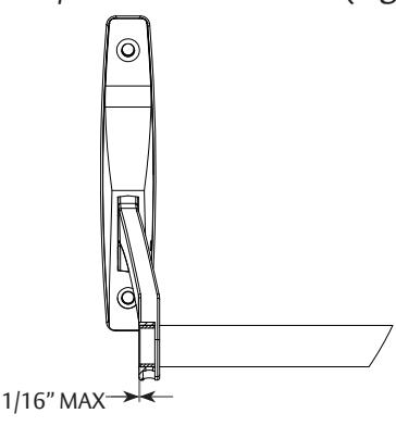
- 2. Mark bar at inactive case & cut. Length of cross bar should be from fl ush to 1/16" less than fl ush. (Figure 11)


Alternately push down on one lever while pushing up on other.
Note: If crossbar does not work freely, check installation for binding of levers due to improper bar length or case misalignment.
Note : If tenon pins are not seated in lever holes, bar will be loose and twist. Repeat rocking procedure.
Note: If after completion of installation, crossbar does not work freely, check installation of binding of levers due to improper bar length or case misalignment.

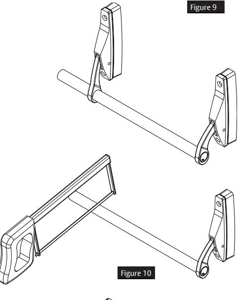
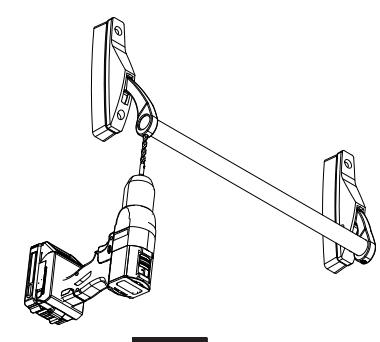
Figure 11
Concealed Vertical Rod Exit Device
Installation Instructions
10 Install Outside Operator
- 1. Following template furnished, mark bolt backset on outside of door.
- 2. Press in top latch plunger screw to project top latch and bottom bolt.
- 3. Put operator in locked position.
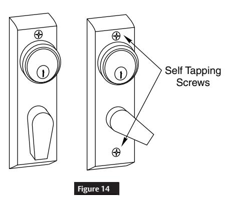
- 4. Center operator on backset line so top side of lifting lever contacts underside of auxiliary lifting fl ange. (Figure 14)
- 5. Spot door through hole at top of operator and drill starting hole with No. 18 drill for self-tapping screw.
- 6. Mount operator with screws furnished.
- 7. Unlock operator and swing operator lever to side retracting latch and bolt. (Figure 15)
- 8. Spot and drill hole with No. 18 drill for self-tapping screw.
- 9. Secure.
NOTE: If door offers too much resistance to self-tapping screw, use next larger drill. (Figure 16)
| Size | % Thread | |||
|---|---|---|---|---|
| No. 18 | 75% | |||
| 11/64" | 70% | |||
| No. 17 | 65% | |||
| No. 16 | 55% | |||
| Figure 15 | ||||

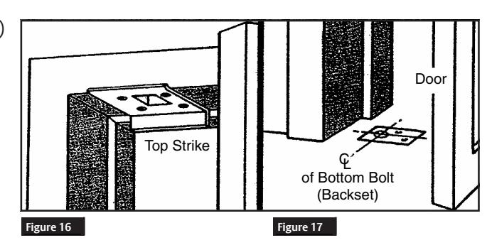
11 Install Strikes
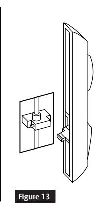
- 1. Apply top strike on header with screws furnished. (Figure 17)
-
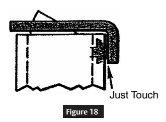
2. Install bottom strike. (Figure 18)
- If not using threshold, mortise bottom strike into fl oor, lining up carefully with bolt centerline.
- With metal threshold, drill 7/8" hole in threshold in line with centerline of bottom bolt.

12 Adjust Plunger Screw
When door is closed against top strike, plunger screw releases top latch and bottom bolt. Adjust so that when door is shut tight, screw head just touches strike. (Figure 19)
11 Test Operation
From Outside: When door is opened by turning operator latch, top latch and bottom bolt should retract and stay retracted until plunger screw is pushed in.
From Inside: When door is opened by depressing crossbar, top latch and bottom bolts should retract, and stay retracted until plunger screw is pushed in.
Lock crossbar in dogged down position. Latch and bolt should be fully retracted.
Note: No dogging feature on "U" series.