Corbin Russwin ED6600 Series Installation Instructions_FM378
Open the original PDF document
View PDF


This product can expose you to lead which is known to the state of California to cause cancer and birth defects or other reproductive harm. For more information go to www.P65warnings.ca.gov.
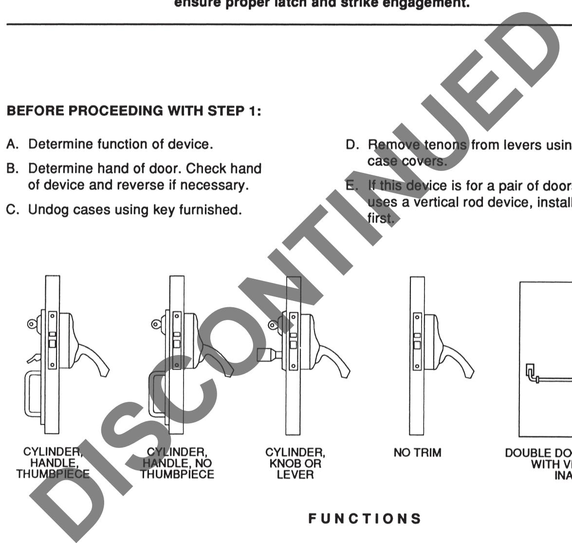
ED6600 Series Mortise Crossbar Exit Device
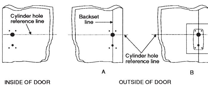
1 MARK INSIDE OF DOOR
Detach device template from mortise template. Using Easy Spot Template Locator, mark two (2) locator points on INSIDE and OUTSIDE of door, approximately 36" and 48" above finished floor line. Draw a vertical line through these points on each side of door. THESE LINES ARE THE BACKSET LINES.
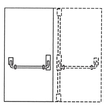
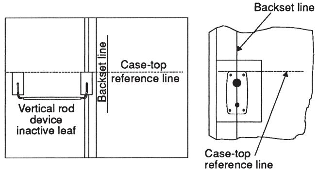
A. When installed on an active leaf of pair of doors in combination with vertical rod device, install vertical rod device first.
Draw a horizontal line from top of vertical rod active case onto active door. This is the CASE TOP REFERENCE LINE. Position device template with CASE TOP REFERENCE LINE and BACKSET LINE. Spot all six (6) holes.
B. When Installed on Single Door
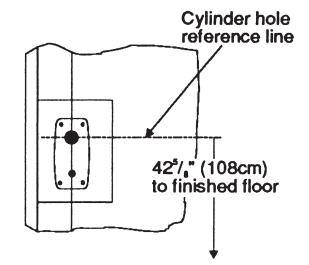
Position bolt template on backset line so that CYLINDER REFERENCE LINE is 42<sup>5</sup>/8" (108 cm) above finished floor line or top of threshold. This will give 37" (94 cm) crossbar height. Spot all six (6) holes.
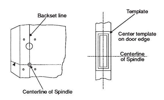
MARK EDGE OF DOOR
Draw horizontal line from SPINDLE CENTERLINE to edge of door. Carry line around onto opposite face of door. BE SURE LINE IS LEVEL.
Position lock template on door face, centering it on door edge and lining up SPINDLE CENTERLINE. Spot mortise area.
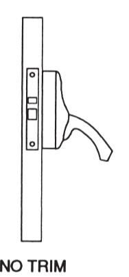
3. MARK OUTSIDE OF DOOR ONLY IF YOUR INSTALLATION HAS OUTSIDE TRIM
Cylinder hole reference line was dimensioned from finished floor. Carefully measure distance from this line to bottom of door. Transfer to outside face of door to spot cylinder hole on backset line previously drawn. Align cylinder hole of trim template with this mark. SPOT ONLY THOSE HOLES WHICH APPLY TO YOUR TRIM'S FUNCTION.

ED6600 Series Mortise Crossbar Exit Device
4 DRILL AND MORTISE
After carefully rechecking all measurements, mortise door for lock. Then drill holes for spindle, trim (if furnished) and active case.
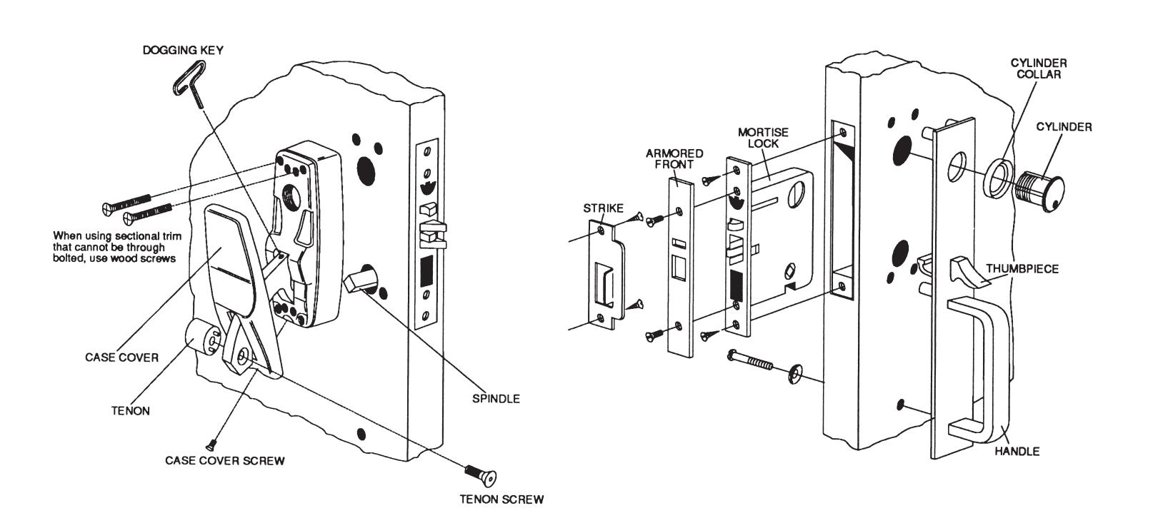
5 INSTALL ACTIVE CASE, LOCK, AND TRIM
Following illustration, insert mortise lock into door and fasten with #12-24 combination screws. Insert spindle into lock hub until roll pin stops spindle travel. Engage active case with spindle and position against face of door. Align trim (if furished) on door and fasten using #12-24 flat head machine screws or optional sex nuts and bolts. Your trim may vary from example shown here.
Screw cylinder (if required) with collar into lock. Tighten cylinder set screw gradually, while testing for proper cam engagement. Keyway should be vertical so that key is inserted with cuts facing up.
NOTE: If cylinder does not thread in smoothly, check for misalignment of cylinder holes in trim, door and lock.
Attach armored front using #8-32 flat head machine screws.
NOTE: Secure all screws with equal torque to avoid binding.
ED6600 Series Mortise Crossbar Exit Device
6 TEST OPERATION
NOTE: Until inactive case is installed (STEP 8), you must support bolt lever for proper latch action.
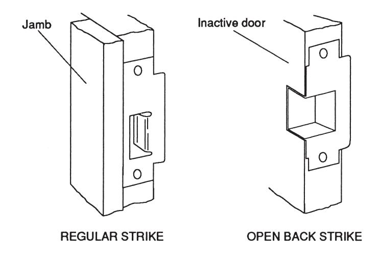
7 INSTALL STRIKE
(Wood Jambs Only) Close door and mark jam or inactive door with centerline of bolt. Mortise and install strike.
OPEN BACK STRIKES are required for inactive door of pair of doors and are handed to suit swing of door.
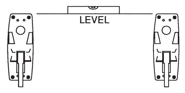
A MOUNT INACTIVE CASE
Place case in desired position and spot four (4) screw holes using case as template. BE SURE CASES ARE LEVEL AND AT SAME HEIGHT. Drill for #12 screws and mount case. If sex nuts and bolts are used, drill 1/4" holes through door and enlarge outside to accept sex nut.
9. REPLACE ACTIVE AND INACTIVE CASE COVERS
Position top of case first, engaging pin on cover in hole in casting. Secure with phillips screws.
ED6600 Series Mortise Crossbar Exit Device
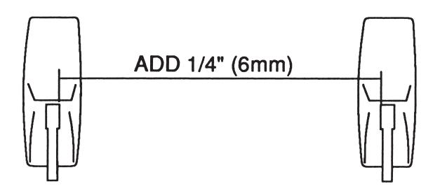
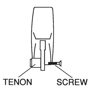
10 INSTALL CROSSBAR
Measure distance between levers near hole where top of lever enters case. Add 1/4" (6mm) to this dimension and cut crossbar to this measurement. Remove burrs on inside and outside of bar.
A. REPLACE TENON IN ONE (1) LEVER
Replace tenon in one lever using dogging key. DO NOT TIGHTEN.
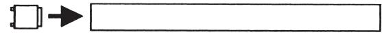
B. PLACE 2nd TENON IN CROSSBAR
Place other tenon into end of crossbar so it is just flush.
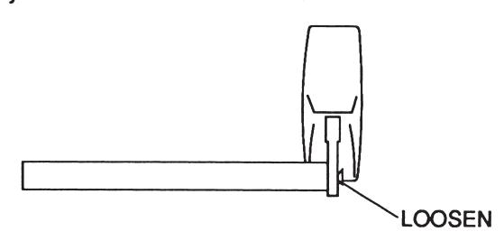
C. PLACE OTHER END OF CROSSBAR OVER TENON PREVIOUSLY SECURED TO LEVER
Set crossbar into recess in lever. If necessary, loosen screw slightly to slide crossbar over tenon.
D. POSITION OTHER END OF CROSSBAR WITH TENON IN RECESS IN OTHER LEVER
Install screw. DO NOT TIGHTEN.
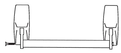
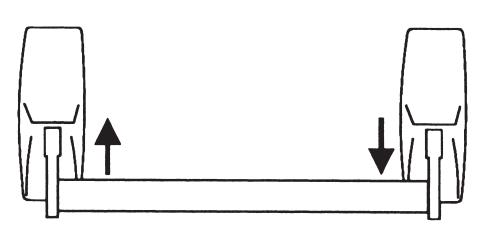
E. SEAT CROSSBAR IN LEVER
Push down lightly on right lever while pulling up lightly on left lever. Alternate procedure as required. This rocking motion will align both tenon pins in lever holes. TIGHTEN SCREWS USING SCREWDRIVER THROUGH BOW OF DOGGING KEY.
NOTE: IF TENON PINS ARE NOT SEATED IN LEVER HOLES, BAR WILL BE LOOSE AND TWISTABLE. REPEAT ROCKING PROCEDURE AS REQUIRED TO ACHIEVE PROPER SEATING.
ED6600 Series Mortise Crossbar Exit Device
TO REVERSE HAND OF DEVICE IF NECESSARY
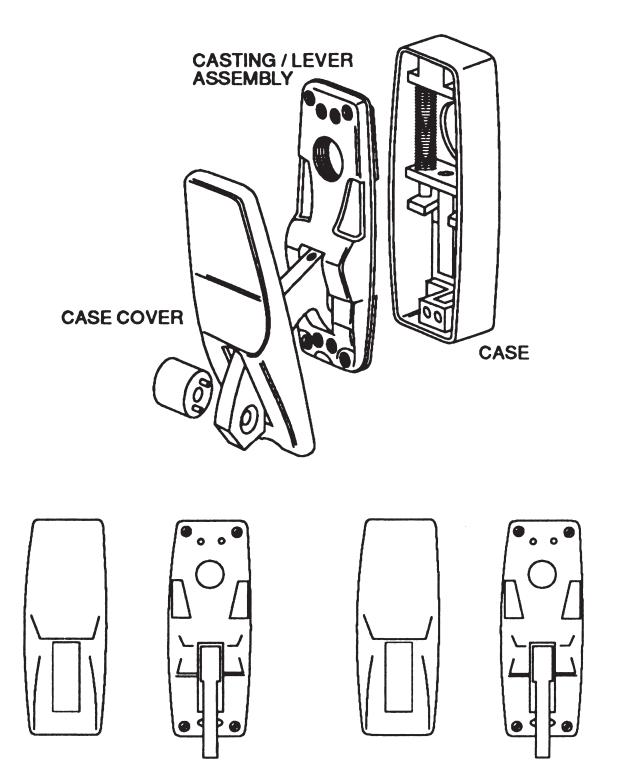
A. REMOVE CASE COVERS
Remove phillips head screw at botom of cover and lift off cover.
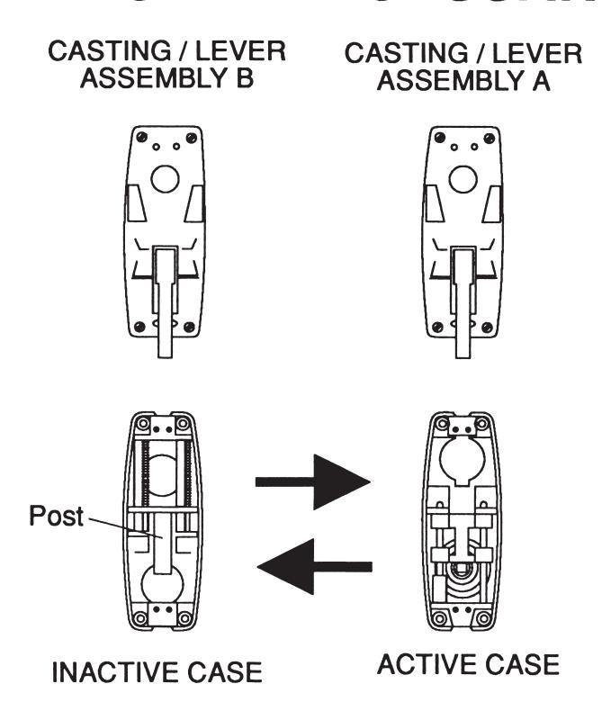
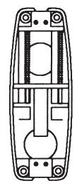
B. REMOVE CASTING / LEVER ASSEMBLIES FROM CASES
Remove four phillips head screws. Place castings on table above the cases. Switch position of cases as shown. DO NOT MOVE CASTING / LEVER ASSEMBLIES.
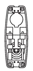
C. REPLACE CASTING / LEVER ASSEMBLIES
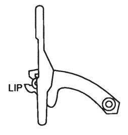
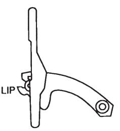
Place casting "A" on INACTIVE CASE, engaging lever lip under finger on bottom of slide. Position casting "B" on ACTIVE CASE so lever lip engages slide hook. SECURE WITH PHILLIPS HEAD SCREWS. DO NOT REPLACE CASE COVERS.
NOTE: Oval recess in levers should be toward center of door when complete.
ED6600 Series Mortise Crossbar Exit Device
IF COMPENSATOR AND HUB BECOME DISASSEMBLED FROM BACKPLATE, REASSEMBLE AS SHOWN COMPENSATOR HUB DOOR HUB DOOR HUB DOOR HUB DOOR HUB DOOR HUB DOOR HUB DOOR HUB DOOR HUB DOOR HUB DOOR HUB DOOR HUB DOOR HUB DOOR HUB DOOR HUB DOOR HUB DOOR HUB DOOR HUB DOOR HUB DOOR HUB DOOR HUB DOOR HUB DOOR HUB DOOR HUB DOOR HUB DOOR HUB DOOR HUB DOOR HUB DOOR HUB DOOR HUB DOOR HUB DOOR HUB DOOR HUB DOOR HUB DOOR HUB DOOR HUB DOOR HUB DOOR HUB DOOR HUB DOOR HUB DOOR HUB DOOR HUB DOOR HUB DOOR HUB DOOR HUB DOOR HUB DOOR HUB HUB DOOR HUB DOOR HUB HUB DOOR HUB HUB DOOR HUB HUB DOOR HUB HUB DOOR HUB HUB DOOR HUB HUB DOOR HUB HUB DOOR HUB HUB HUB DOOR HUB HUB HUB HUB HUB HUB HUB HUB HUB HUB
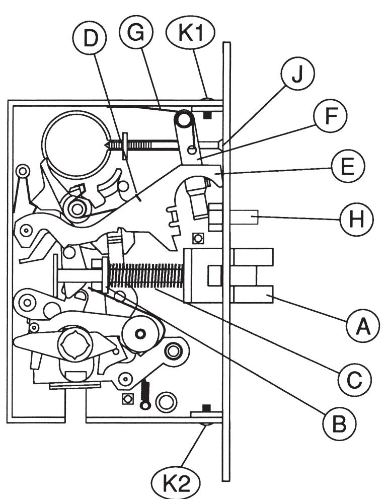
- 1. Remove three (3) screws and remove case cap.
- 2. Remove and reverse latch A. Be sure washer B remains against latch spring C when reinstalling latch A.
- 3. Disengage spring D of large horizontal deadlatch lever E and remove that lever.
- 4. Remove small vertical deadlatch lever F and spring G.
- Reverse deadlatch H so concave surface faces same direction as bevel of main latch A.
- 6. Reinstall lever F and spring G. Reinstall lever E, being careful to reengage spring D.
- 7. Move cylinder set screw J to opposite side.
- 8. Replace case cap and tighten three (3) cap screws securely.
- Reverse lock front bevel by loosening (not removing) two screws K in top and bottom edges of case. Pivot front to proper bevel (or flat) and retighten screws.
- 10. Check for smooth latch, cylinder and knob/lever operation before installing into door.


In U.S.: Corbin Russwin, Inc. 225 Episcopal Road Berlin, CT 06037 USA Phone: 800-543-3658
Technical Product Support: Phone: 888-607-5703
In Canada: ASSA ABLOY Door Security Solutions Canada 160 Four Valley Drive Vaughan, Ontario, Canada L4K 4T9 Phone: 800-461-3007
FM378 12/18 Patents Pending Printed in USA