Corbin Russwin ED6400A Series Discontinued Installation Instructions_FM426D
Open the original PDF document
View PDFINSTALLATION INSTRUCTIONS:
Fire Rated Vertical Rod Device (Model 73)
No's U770-73, U771-73, U778-73, U780-73, U781-73, U782-73, U788-73, U789-73, 3210U-73, 3220EOU-73, 3220U-73, 3223U-73, 3224U-73. 3225U-73. 3245U-73. 3246U-73
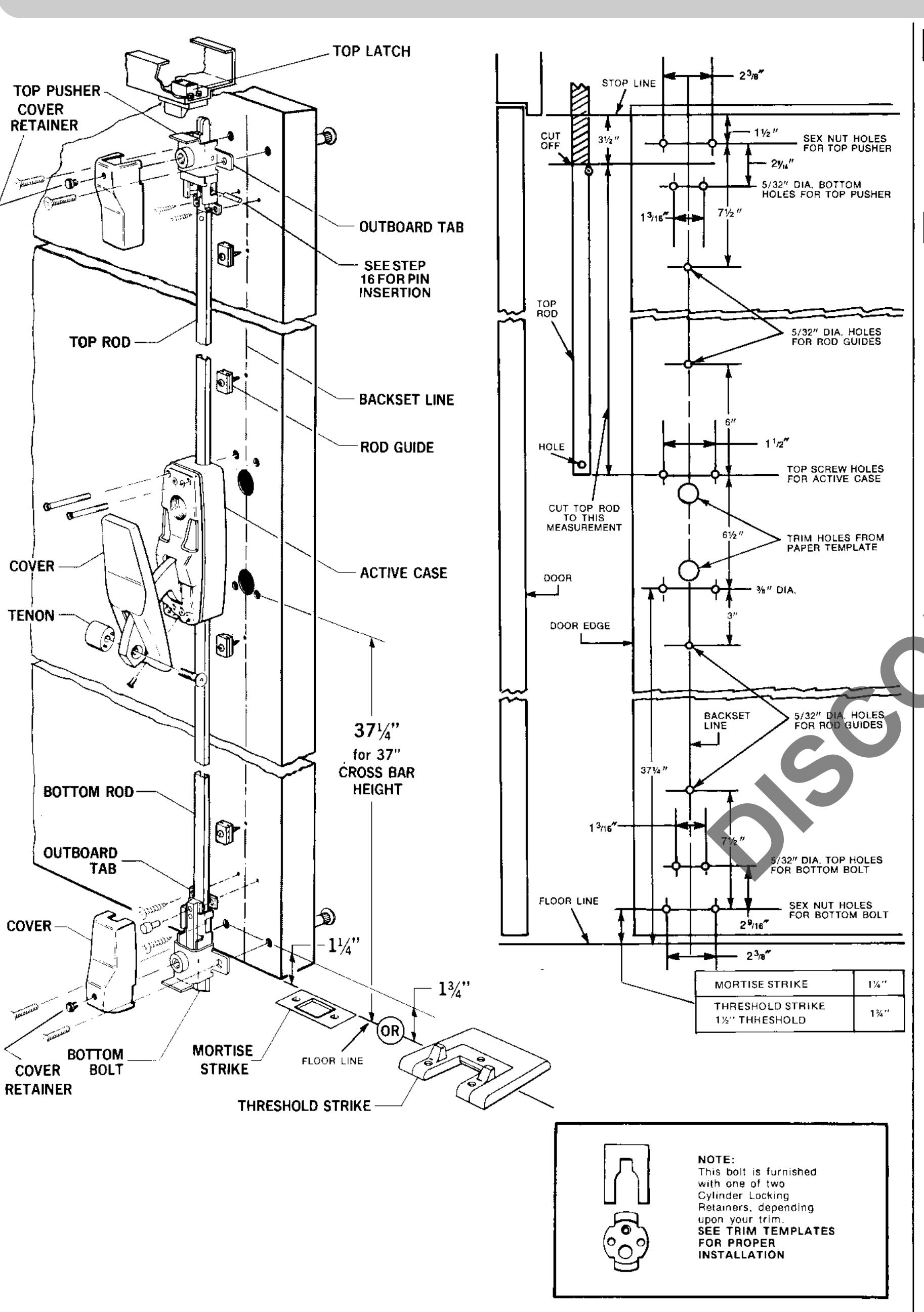
TEMPLATE THE DOOR:
A. Draw a backset line for the full height of the inside of the door. 2-3/4" is the recommended backset but it may be varied
B. Locate and drill holes for the active case, the rod guides and the sex nuts for the top pusher and bottom bolt assemblies. C. If you have outside trim, draw a backset line on the outside of the door. Locate and drill the required holes from the marked-up trim templates provided.
2 CUT THE TOP ROD:
With the door closed, carefully measure 31/2" down from the top stop and draw a short horizontal line across the backset (ine on the inside of the door.
Carefully measure from that crossline to the centerline of the top screw holes (A) for the active case.
Cut the top rod to that measured dimension. Do not cut
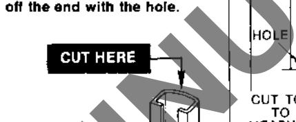
DO NOT CUT
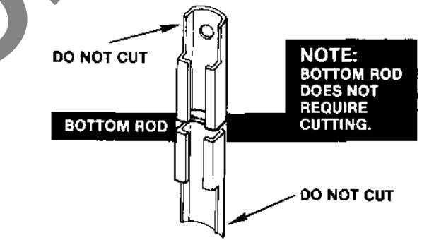
3 INSTALL THE TOP ROD CONNECTOR:
Slip the connector assembly into the cut-off end of the top rod Drill a 1/8" diameter hole through the rod wall using the hole in the back of the connector as a guide.
Insert the rivet into the drilled hole from the front of the rod. Hammer the pin in the head of the rivet flush with the top of the head to fasten the rivet.
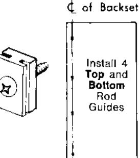
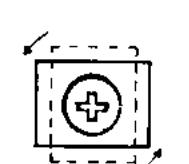
4 INSTALL THE ROD GUIDES:
Fasten the four rod guides along the backset line on the inside of the door. It is important that the guides be central for best operation of the rods. Do not use a hole that has been drilled off-center. Drill another hale on center close to the
discarded hole. Do not bring the screw heads down tight on the quides. The quides must be free to pivot.
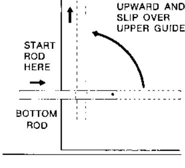
5 INSTALL THE TOP ROD:
With the door open, turn one end of the uppermost rod quide toward the edge of the door. Holding the top rod horizontally, slip the open end into the slots of the guide. Pivot the end of the rod with the hole in it downward and slip it into the slots of the lower guide.
1 ROD GUIDES MUST BE FREE TO PIVOT TURN ROD DOWNWARD AND SLIP OVER GUIDE DO NOT DOWN TIGHT
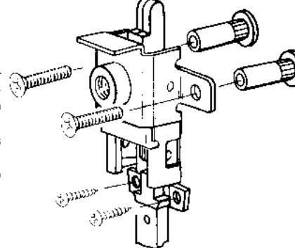
6 INSTALL THE TOP PUSHER:
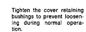
Using wrench furnished, remove cover retaining bushing and cover, Fasten top pusher frame to door with #12-24 oval head thru bolts and sex nuts. Spot 1/32" dia. holes for lower side tab screws and install #12 x 1 lg. round head sheet metal
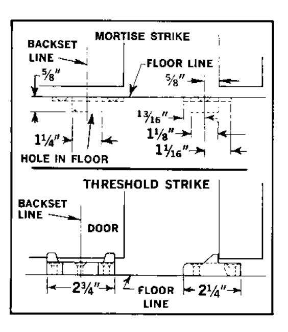
INSTALL THE BOTTOM STRIKE:
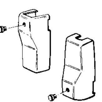
Install Mortise Strike or Threshold Strike using Backset Line scribed on door as Center Line.
MORTISE STRIKE --- Mortise floor 1/8" deep with screw holes of Strike %" from face of door when door is shut against stop. Secure with Screws and Anchor Bolts.
THRESHOLD STRIKE - Position Threshold with strike hole located per dimensions shown. Install Strike in hole and secure with screws and anchor bolts. Properly installed, Strike should be centered on Backset Line with Strike against the door.
8 | INSTALL THE BOTTOM ROD:
With the door open, turn one end of the lowest rod guide toward the edge of the door. Holding the bottom rod horizontally, slip the end into the slots of the guide. Pivot the end of the rod with the hole in it upward and slip it into the slots of the upper guide.
TURN ROD
INSTALL THE BOTTOM BOLT
Using wrench furnished, remove cover retaining bushbottom rod and place bottom bolt assembly against door. Allow rod to drop between bolt tail and frame of bottom bolt assembly. Fasten frame to door with #12-24 thru bolts and sex nuts. Spot 1/32" dia. holes for top side tab screws and install #12 x1" lg. round head sheet metal screws.
INSTALL TRIM:
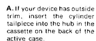
If your device does not have outside trim, proceed with Step No. 11. Install trim in accordance with template furnished.
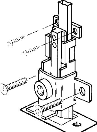
INSTALL THE ACTIVE CASE:
HUB FULLY CLOCKWISE
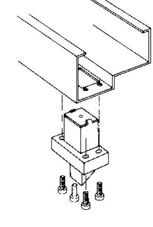
Remove the cover and install the active case.
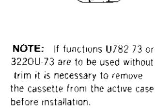
WHEN INSTALLED Note: The cassette hub as shipped is in a fully clockwise position and must remain so for correct operation. If, for any reason the hub has been rotated from the fully clockwise position, it must be returned to it before the cylinder tailpiece is inserted. Otherwise, the kev mechanism will not function properly
B. Insert the top projection at the back of the active case slide into the hole in the top rod
with the two top screws only - leave the screws loose so that the bottom of the active case can be lifted approximately 1/2" away from the door
D. Lift the bottom of the active case away from the door. Slide the rod underneath the case and insert the projection on the back of the active case slide into the hole in the rod. If you have outside trim, be sure the tail of knob trim is below the operating slide tab which extends from the Herer to trim
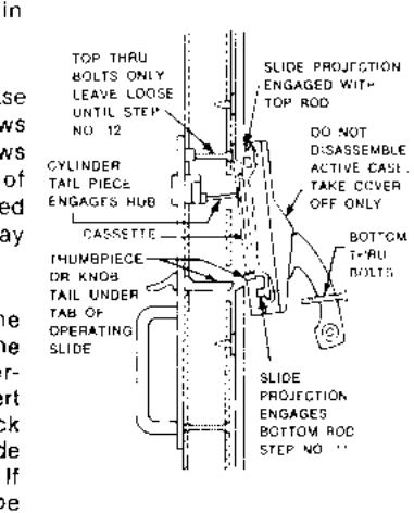
12 TIGHTEN THE ACTIVE CASE SCREWS:
Install the two bottom screws for the active case. Tighten all four screws.
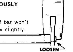
CHECK POINT: Check to be sure the rods will drop fully after being raised and released. If they do not drop freely:
A. Are the rod guides central?
B. Are the guide screws too tight?
C. is the surface of the door flat along the back set line? If not, loosen the guide screws to compensate for the difference in levels.
INSTALLATION INSTRUCTIONS:
Fire Rated Vertical Rod Device (Model 73)
No's U770-73, U771-73, U778-73, U780-73, U781-73, U782-73, U788-73, U789-73, 3210U-73, 3220E0U-73, 3220U-73, 3223U-73, 3224U-73, 3225U-73, 3245U-73, 3246U-73
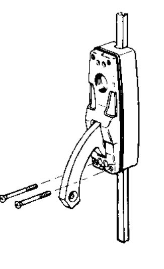
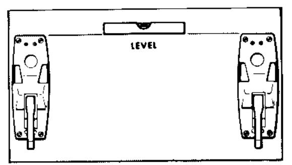
13 INSTALL THE INACTIVE CASE:
Place Case in desired position and spot 4 screw holes using Case as template. BE SURE CASES ARE LEVEL AT SAME HEIGHT. Drill for #12 screws and mount case.
NOTE: The spring power of the Inactive Case is calculated to support crossbars for doors up to 48" in width. If your order specified a door 48" or greater in width the Inactive Case is furnished with an extra spring and guide rod. (see step 13A)

If your door width is 48" or greater and the Inactive Case does not contain the extra spring and guide rod they should be ordered and installed in the following way. (1) Remove top casting and lever assembly. (2) Remove case wrap around. (3) Mount back plate on door. (4) Insert guide rod and spring above post in center of case as shown. (5) Use case wrap around to compress the spring and snap wrap around into place. (6) Replace top casting and


Position top of case first. engaging lip on cover and case. Secure with Phillips
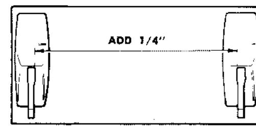
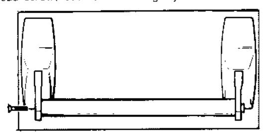
INSTALL THE CROSSBAR:
Measure distance between Levers near hole where top of Lever enters Case. Add 1/4" to this dimension and cut Cross-Bar to this measurement. Remove burrs on inside and outside of bar
[A] INSTALL TENON ON 1 LEVER
Using Dogging Key furnished. DO NOT TIGHTEN.
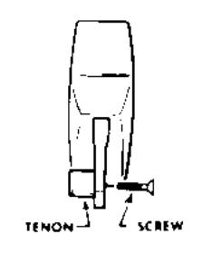
(B) PLACE 2ND TENON IN CROSS-BAR
Place other Tenon into end of Cross-Bar so it is just flush with
[C] PLACE OPEN END OF BAR OVER TENON PREVIOUSLY SECURED TO LEVER
Set bar into recess in Lever. If bar won't slide over Tenon, loosen screw slightly.
[D] POSITION OTHER END OF BAR IN RECESS IN OTHER
Thread screw, but don't seat tightly
(E) SEAT BAR IN LEVER
Push down easily on right Lever while pulling up on left. Alternate procedure. This rocking will assure line-up of 2 Tenon pins in holes in lever. TIGHTLY SECURE SCREWS USING SCREWDRIVER THROUGH BOW OF DOG-
GING KEY FURNISHED.
IF TENON PINS ARE NOT SEATED IN LEVER HOLES, BAR WILL BE LOOSE AND TWIST. REPEAT ROCKING PROCEDURE.
16 ADJUST THE TOP ROD:
A. Press levers at top of Pusher Assembly toward door. Force slide to down position by pushing from top of frame.
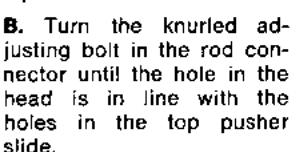
C. Insert the 3/4" diameter connecting pin through the side of the frame into the holes in the slide and bolt
If the top rod has been correctly adjusted the top pusher will retain the rods in an UP position after the crossbar has been depressed or when the outside trim is operated. Pressing the levers at the top of the Pusher Assembly should allow the rods to drop. If after the crossbar has been depressed or the trim has been operated, the rods do not remain in the UP position, pull the connecting pin and turn the adjusting bolt outward one turn at a time as required. Do not overadjust.
FASTEN BOTTOM BOLT:
A. Depress crossbar to place rods in UP position.
B. Place card-board over top of strike to support bottom bolt Drill 1/4" diameter hole in bottom rod using one of two holes in bolt tail as a guide. Insert connecting pin through hole in bolt
Two holes are provided in bottom bolt to allow correction if hole is drilled in
wrong position.
Tear card-board spacer from for active and inactive
REPLACE TOP PUSHER & BOTTOM BOLT COVERS
DRILL 1/4" HOLE IN ROD
USING HOLE IN BOTTOM
BOLT AS GUIDE
INSTALL TOP LATCH
Using #12-24 x ¾ " long fillister head machine screws. install top latch in header cut-out. Adjust so that rods drop when door is closed.
TEST OPERATION
When crossbar is depressed or outside trim is operated, the bottom bolt should clear the strike and the top latch forced out of engagement with the top pusher assembly to allow the door to open. Rods will remain in the UP position while door is open. Rods will drop automatically when the door closes; Top latch will enter the top pusher assembly and bottom bolt will engage
The key locks and unlocks the device. When locked the thumbpiece or knob will operate but will not open the door.
TO REVERSE HAND OF BOLT IF NECESSARY ....
A. REMOVE CASE COVERS - Remove Phillips Head Screw at bottom of Cover and lift off Cover.
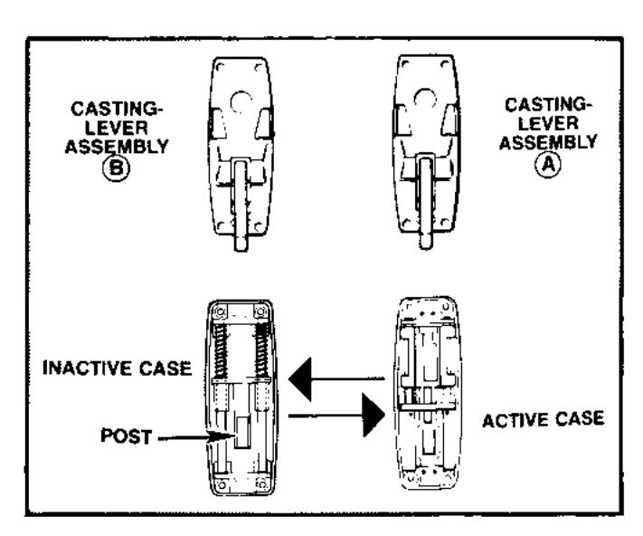
B. REMOVE CASTING-LEVER ASSEMBLIES FROM CASES - Remove 4 Phillips Head Screws. Place Castings on table above the cases.
SWITCH POSITION OF CASES AS SHOWN. DO NOT MOVE TOP CASTING AND LEVER ASSEMBLIES.
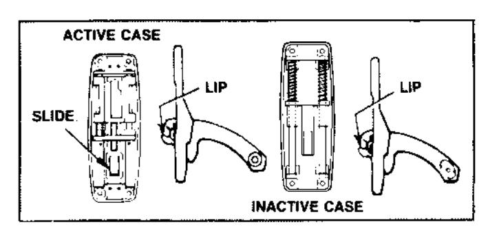
NOTE: OVAL RECESS IN LEVERS SHOULD BE TOWARD. CENTER OF DOOR WHEN COMPLETE.
C. REPLACE CASTING-LEVER ASSEMBLIES - Put Casting "A" on INACTIVE CASE, engaging Lever Lip under Post on bottom of slide. Position Casting "B" on ACTIVE CASE so Lever Lip enters hole in slide, SECURE WITH PHILLIPS HEAD SCREWS. DO NOT REPLACE CASE COVERS.

Corbin Russwin, Inc. 225 Episcopul Road Berlin, CT 06037 USA Phone: 860-225-7411 Fax: 860-828-7266