Corbin Russwin ED6400 Series Discontinued Installation Instructions_FM391
Open the original PDF document
View PDFED6400 Series Surface Vertical Rod Exit Device
Installation Instructions
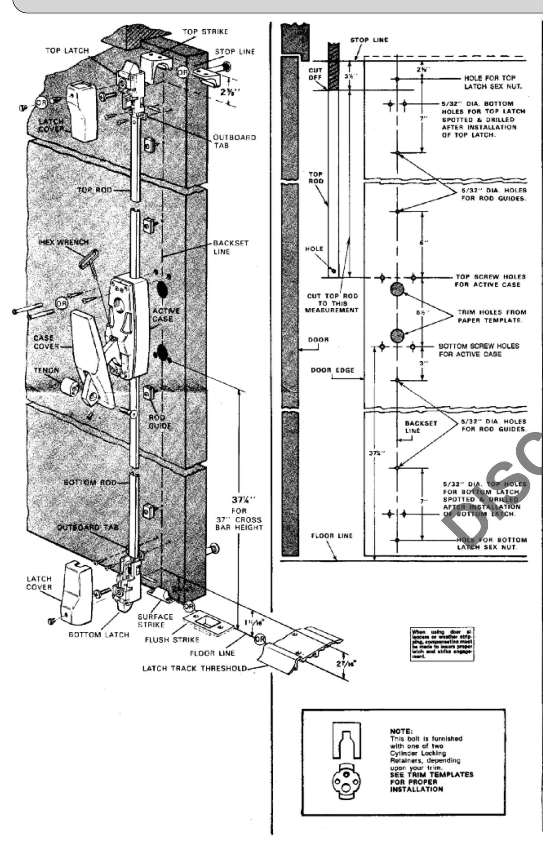
TEMPLATE THE DOOR:
A. Draw a backset line for the full height of the inside of the door. 2-3/4" is the recommended backset but it may be varied to suit atile conditions.
B. Locate and drill holes for the active case, the rod guides and the sexnuts for the top and bottom latch assemblies. Do not drill holes for the two outboard tabs on the top and bottom latch frames at this time.
C-If you have outside trim, draw a backent line on the outside of the door. Locate and drill the required holes from the trim templates provided.
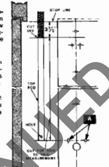
CUT THE TOP ROD:
With the door closed, carefully measure 3 1/2" down from the top stop and draw a short horizontal line across the backset line on the inside of the door.
Carefully measure from that crossline to the centerline of the top screw holes (A) for the active case
Cut the top rod to that measured dimension. Do not cut off the end with the

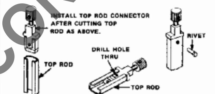
INSTALL THE TOP ROD CONNECTOR:
Slip the connector assembly into the sut-off end of the top rod. Drill a 1/8' diame is hole through the rod wall using the hole in the back of the connector as a guilde.
Insert the rivet into the critical hale from the front of the rod. Herimer the on in the head of the rivet flush with the top of

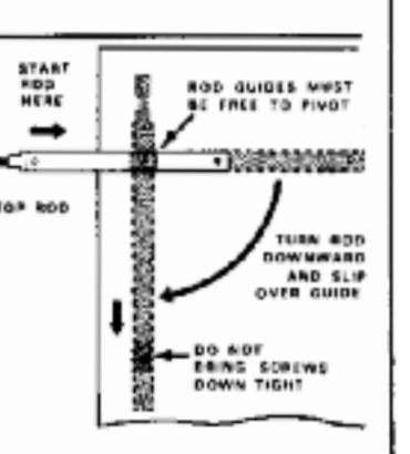
INSTALL THE ROD GUIDES:
Fasten the four rod guides along the backset line on the inside of the door. It is important that the guides be central for best operation of the rods. Do not use a hole that has been drilled off-center. Drill another bole on center close to the discarded hole.
Do not bring the screw heads down tight on the guides. The guides must be free to pivot.
C of Backset

INSTALL HANDLE TRIM:
If your device does not have outside trim or if it has knob trim, proceed to Step
If your device has handle trim, fasten it to the door with the bottom through bolt for the grip. If your cylinder is to be fastened with a retainer plate from the inside of the door. install the plate now. Refer to trim template furnished.

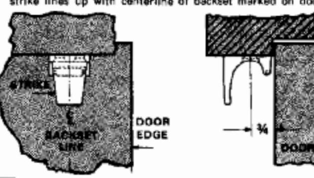
INSTALL THE TOP STRIKE:
Close door and place strike against door so that centerline of strike lines up with centerline of backset marked on door.

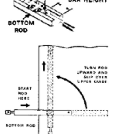
INSTALL THE TOP ROD:
With the door open, turn one end of the uppermost rod guide toward the edge of the door. Holding the top red herizontally, slip the open and into the slots of the guide. Pivot the end of the rod with the hole in it downward and slip it into the slots of the lower guide.

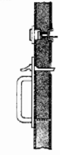
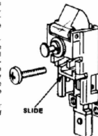
INSTALL THE TOP LATCH:
Remove the cover from the top latch. Replace the plunger assembly or cover retainer assembly on the uncovered latch assembly Fasten the top latch assembly to the door with the 1/4-20 pan head screw and sexnut. Adjust the assembly for minimum door rattle when the latchbolt is fully projected (to project the latchbolt pull down on the slide in the frame).
Do not install the screws for the two tabs at the side of the frame at this time.

INSTALL KNOB TRIM:
If your device does not have outside trim, proceed with Step No. 10. Install trim in accordance with template furnished

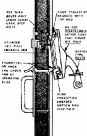
INSTALL THE ACTIVE CASE:
Remove the cover and install the active case.
A- If your device has outside trim, insert the cylinder tallpiece into the hub in the cassette on the back of the
B. Insert the top projection at the back of the active case slide into the hole in the top rod.
C. Fasten the active case street with the two top screws only - leave the screws loose so that the bottom of the active case can be lifted approximately 1/2" away from the door.
Note: If ED6400 is to be used without trim you must remove cassette from active case before installation.
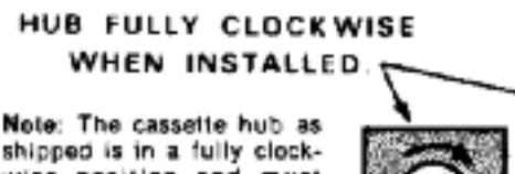
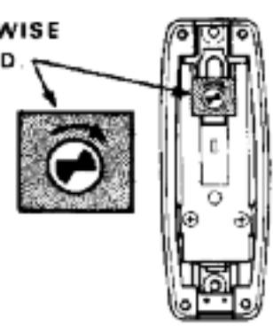
shipped is in a fully clockwise position and must remain so for correct operation. If, for any reason the hub has been rotated from the fully clockwise position, it must be returned to it before the cylinder tailpiece is inserted. Otherwise, the key mechanism will not function properly.

11 INSTALL THE BOTTOM ROD:
Note: The regular length of the bottom rod is suitable for a crossbar height of 37" from the floor. The adjusting bolt in the bottom of the rod will compensate for minor variations from that height. If the crossbar height is as short as 36-1/2" from the floor, it will be necessary to out the bottom rod. Remove the adjusting bolt from the rod and cut off the skirt at the bottom of the rod so that the rod is flush with the bottom of the adjusting bolt insert.
CUT-OFF FOR
SHORT CROSS
With the door open, turn one end of lowest rod guide toward the edge of the door. Holding the bottom rod horizontally, slip the open end into the slots of the guide. Pivot the end of the red with the hole in it upward and alip it into the slots of the upper guide.
Lift the bottom of the active case away from the door. Slide the rod underneath the case and insert the projection on the back of the active case slide into the hole in the rod. If you have outside trim, be sure the tail of the thumbolece or knob trim is below the operating slide tab which extends from the cassette. Refer to trim template.

TIGHTEN THE ACTIVE CASE SCREWS:
Install the two bottom screws for the active case Tighten all four screws.
CHECK POINT: Check to be sure the rods will drop fully after being raised and released. If they do not drop freely:
A. Are the rod guides
central? B. Are the guide screws too
C. Is the surface of the door flat along the back set line? If not, loosen the guide screws to compensate for the difference in levels.
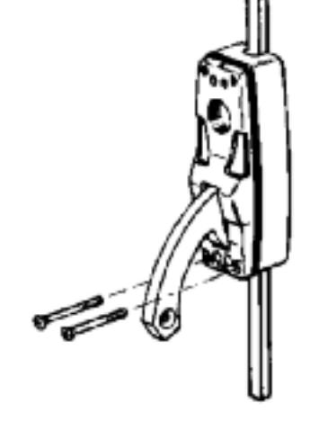

INSTALL THE INACTIVE CASE:
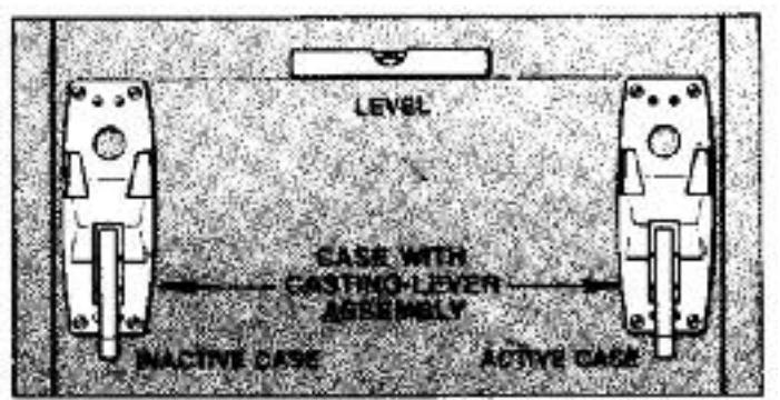
Place Case in desired position and spot 4 screw holes using Case as template. BE SURE CASES ARE LEVEL AT SAME HEIGHT. Drill for #12 screws and mount case.
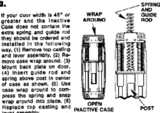
NOTE: The spring power of the Inactive Case is calculated to support crossbars for doors up to 46" in width. If your order specified a door 48" or greater in width the Inactive Case is furnished with an extra spring and guide rod. (see step 13A)
ED6400 Series Surface Vertical Rod Exit Device
Installation Instructions

tt your door width is 48" or greater and the inactive Case does not contain the extra spring and guide rod they should be ordered and installed in the following way. (1) Remove top casting and lever assembly. (2) Remove case wrap around. (3) Mount back plate on door. (4) Insert guide rod and spring above post in center of case as shown. (5) Use case wrap around to compress the spring and snap wrap around into place. (6)

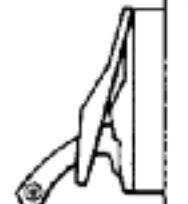
REPLACE THE ACTIVE AND INACTIVE CASE COVERS:
Position top of case first, engaging lip on cover and case. Secure with Phillips Screw.
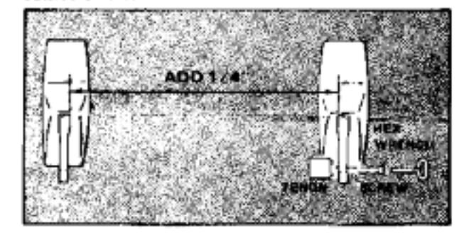
INSTALL THE CROSSBAR:
Measure distance between Levers near hole where top of Lever enters Case. Add 1/4" to this dimension and cut Cross-Bar to this measurement. Remove burrs on inside and outside of bar.
A. PLACE TENON ON 1. LEVER
Using Hex Wrench furnished. DO NOT TIGHTEN
NOTE: Pins in Tenon line up with holes in
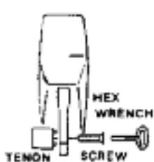
B. PLACE 2nd. TENON IN CROSS-BAR
Place other Tenon into end of Cross-Bar so it is just flush with end of bar
C. PLACE OPEN END OF CROSS-BAR OVER TENON PREVIOUSLY SECURED TO LEVER
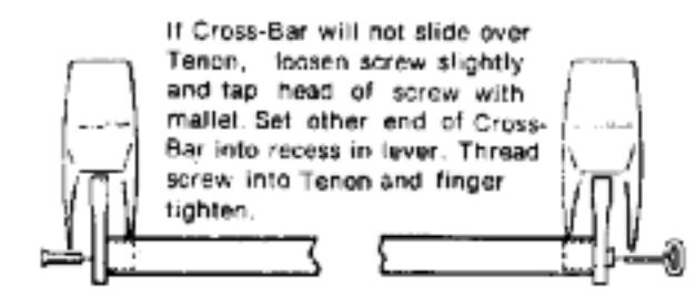
D. SEAT CROSS-BAR IN LEVER
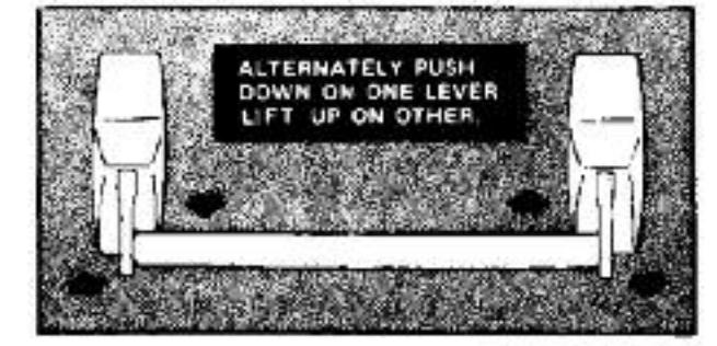
(D. CONTINUED)
Rock Cross-Bar by alternately pushing down on one lever while tifting on other. This rocking will assure line-up of 2 Tenon pins in
TIGHTLY SECURE SCREWS USING SCREWDRIVER THROUGH BOW OF HEX WRENCH FURNISHED.
IF AFTER COMPLETION OF INSTALLATION, CROSS BAR DOES NOT WORK FREELY, CHECK INSTALLA-TION FOR BINDING OF LEVERS DUE TO IMPROPER BAR LENGTH OR CASE MISALIGNMENT.

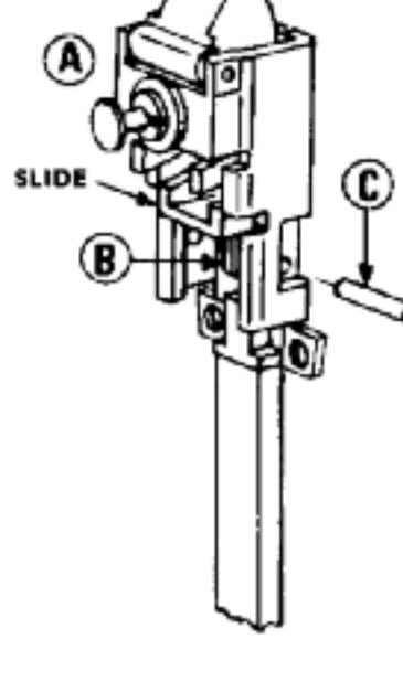
ADJUST THE TOP ROD:
A Pull down on the top latch slide to fully project the top latchbolt.
B Turn the knurled adjusting bolt in the rad connector until the hole in the head is in line with the holes in the slide.
C Insert the 3/16" diameter connecting pin through the side of the frame into the holes in the slide and

A. If the top rod has been correctly adjusted, the top latchbolt will retract to clear the strike roller when the crossbar is depressed or when the outside trim is
B. If your device has been furnished with a free type latch, the latchbolt will project automatically when the crossbar is released. After top rod adjustment - open door and allow to close under own power. If latch does not retract when making contact with strike rollers, turn adjustment bolt outward one turn at a time until latch bolt retracts.
C. If your device has been furnished with a holdback type latch, the latchbolt will remain retracted when the crossbar or outside trim is released while the door is open. Depressing the plunger at the top of the latch assembly will project the latchbolt. If the latchbolt does not remain retracted after the crosstar or trim has been released, pull the connecting pin and turn the adjusting bolt outward one turn. If necessary, repeat this procedure one turn at a time until the latchbolt goes into the holdback condition.
D. If the action of the latch is aluggish, it is most likely that the rods are not dropping freely. Review CHECK POINT under

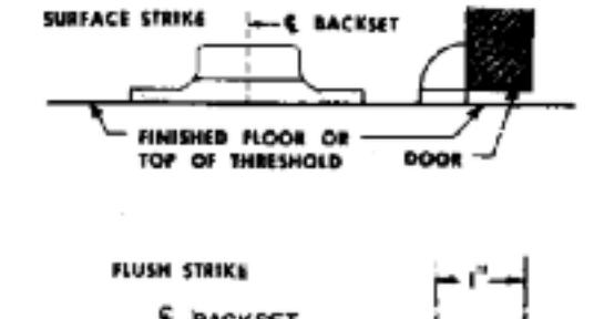
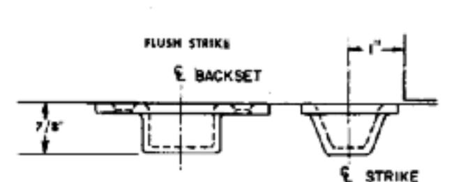
INSTALL THE BOTTOM STRIKE:
If threshold is not used, mount bottom strike. SURFACE STRIKE: Center on Backset Line on door. With door shut against stop, hold Strike against door at FLUSH STRIKE: Center on Backset Line on door. Mortise floor 7/8" deep with Center Line of Strike 1" from face of door when door is shut against stop.
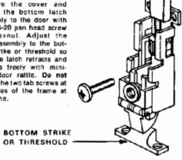
18 INSTALL THE BOTTOM LATCH:
Remove the cover and fasten the bottom latch assembly to the door with the 1/4-20 pan head screw and sexnut. Adjust the latch assembly to the bottom strike or threshold so that the latch retracts and projects freely with minimum door rattle. Do not install the two tab screws at the sides of the frame at
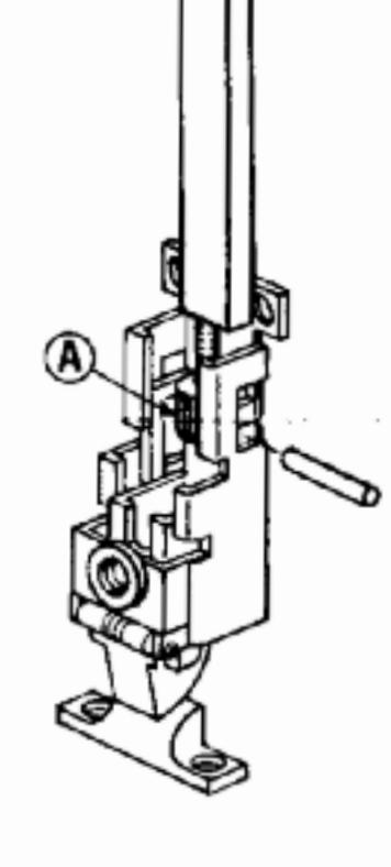
ADJUST THE BOTTOM ROD:
With the latchbolt fully projected, turn the knurled adjusting bolt A until the connecting pin can pass through the side of the frame, under the hooks of the latch slide legs and through the hole in the bolt
CHECK POINT: When the bottom rod has been correctly adjusted, depressing the crossbar or operating the outside trim should retract the bottom latchbolt to clear the strike or threshold. If the latchbolt does not clear, pull the connecting pin and turn adjusting bolt inward one turn. Repeat the procedure one turn at a time as required
CHECK POINT: If your device has been furnished with the degging feature, dog down the crossbar. The top and bottom latches should clear the strikes. If they do not clear, readjust the top and/or bottom rods as required.
INSTALL THE TOP AND BOTTOM LATCH FRAME TAB SCREWS:
Through the hole in each frame tab, spot and drill a 5/32" diameter hole. Install the #12 round head sheet metal/wood
REPLACE TOP AND BOTTOM LATCH COVERS:
USE SPANNER WRENCH PACKED WITH THE EXIT DEVICE TO TIGHTEN THE COVER RETAINING
TEST OPERATION
From The Inside: When the prosphar is depressed, the latchbolts should retract to clear the strikes. Holdback type tatches will remain retracted while the door is open and will project automatically when the door is closed. Free type latches will project as soon as the crossbar is released. When the crossbar is dogged down, the latches remain retracted to allow the door to be free swinging.
From The Outside: The key locks and unlocks the device. When locked, the thumbpiece or knob will operate but will not retract the latches. The doors will not open.
Turning the key counterclockwise unlocks the device. Operating the thumbpiece or knob will retract the latches allowing the door to open. Free type latches will project automatically when the thumbpiece or knob is released. Holdback type latches will remain retracted while the door is
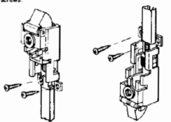
TO REVERSE HAND OF BOLT IF NECESSARY ...
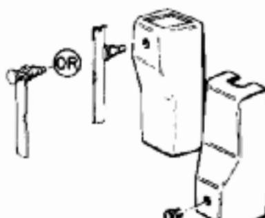
A. REMOVE CASE COVERS - Remove Phillips Head Screw at bottom of Cover and lift off Cover.
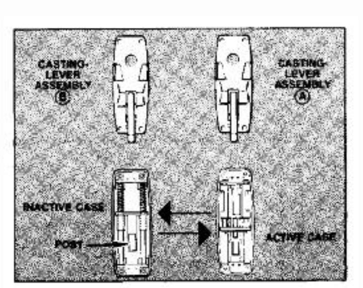
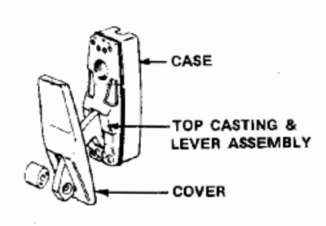
REMOVE CASTING-LEVER ASSEMBLIES FROM CASES - Remove 4 Phillips Head Screws. Place Castings on table above the cases.
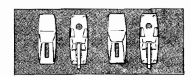
SWITCH POSITION OF CASES AS SHOWN. DO NOT MOVE TOP CASTING AND LEVER ASSEMBLIES.
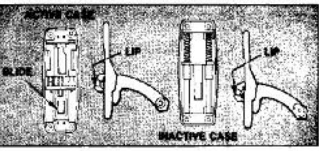
NOTE: OVAL RECESS IN LEVERS SHOULD BE TOWARD CENTER OF DOOR WHEN COMPLETE.
C. REPLACE CASTING-LEVER ASSEMBLIES - Put Casting "A" on INACTIVE CASE, engaging Lever Lip under Post on bottom of slide. Position Casting "B" on ACTIVE CASE so Lever Lip enters hole in slide, SECURE WITH PHILLIPS HEAD SCREWS, DO NOT REPLACE CASE COVERS.

Corbin Russwin, Inc. 225 Episcopal Road Berlin, CT 06037 USA Phone: 800-543-3658
Technical Product Support: Phone: 888-607-5703
In Canada: ASSA ABLOY Door Security Solutions Canada 160 Four Valley Drive Vaughan, Ontario, Canada L4K 4T9 Phone: 800-461-3007
FM391 Rev. 10/13 Printed in U.S.A.