Corbin Russwin ED5860 Series Concealed Vertical Rod Installation Instructions
Open the original PDF document
View PDFED5860 (B) (F) Series Concealed Vertical Rod Exit Devices
Installation Instructions
FM 544 1/98 (617416044)
Outside Tri
Device is packed read any compatible Trin
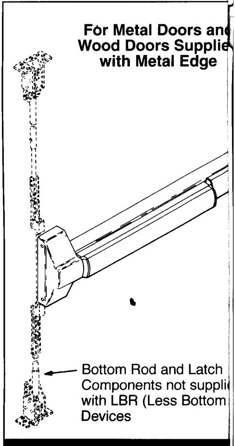
CVR Rod Extension Assy -24" long for doors up to 10'
To Change Hands RHR Device LHR Device Lin Block Vertical Lifter Assembly Vertical Lifter Assembly (4) 8-32 x 3/16" PPHMS (4) 8-32 x 3/16" PPHMS RHR Door LHR Door
Rod)
M
for
Rod Extension Options 2'' (51mm) 6'' (152mm)
Mississauga, On Phone: (905) 672-622
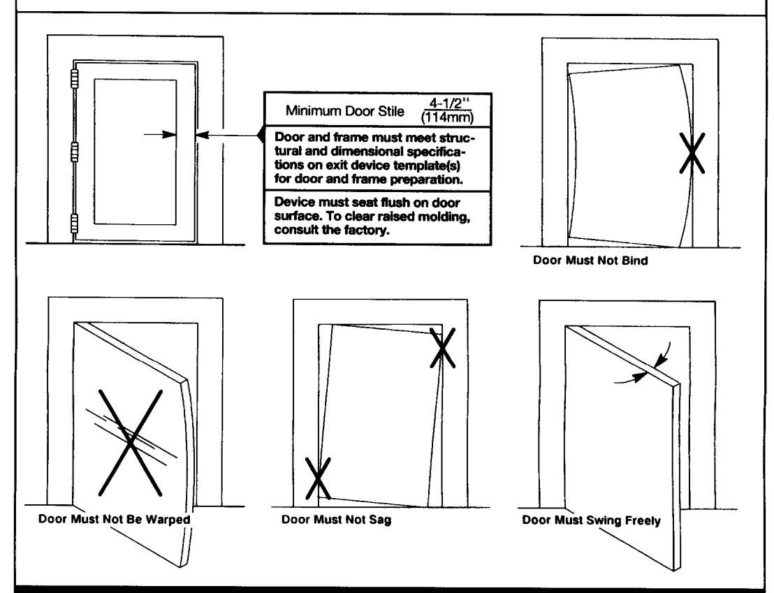
Check Before Starting
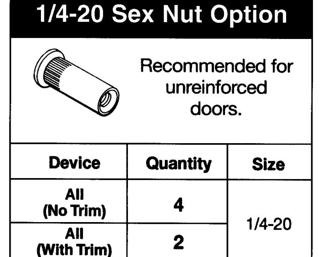
Unreinforced Doors or Frames
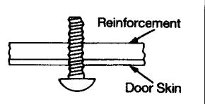
Doors and Frames with walls having a structural thickness (metal skin plus reinforcement) to engage less than (3) full screw threads, are considered unreinforced.
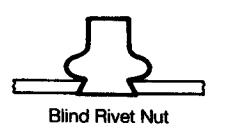
Unreinforced Doors: Use SNB (sex nuts and bolts), or Blind Rivet Nuts.
Unreinforced Frames: Use Blind Rivet Nuts.
(Special Head)
Recommended fasteners for unreinforced openings are not necessarily supplied by Corbin Russwin.
12 (303!!!!!)
(Specify Device Finish)
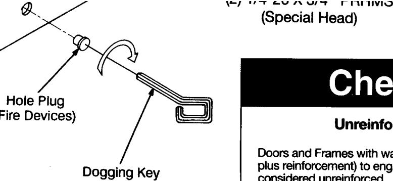
Dogging
to hold bolts retracted and epressed, for push-pull door operation.
To Dog Device
ogging key. uchbar depressed. y 1/4 turn cłockwise.
are of fire labeled devices.)
Maintenance
- 1. Periodically remove covers and coat mechanisms with a silicone base lubricant. This is particularly required in corrosive environments for proper product function.
- Check mounting fasteners periodically. Retighten if found loose. Apply screw. locking compound (available at automotive part stores) or change part fasteners if screws continue to back up.
- 3. Periodic checks (and adjustments) of rods is required, to compensate for changes in the opening (e.g.: door sagging).

In U.S.: Corbin Russwin, Inc. 225 Episcopal Road lin, CT 06037 USA Fax: (860) 828-7266
In Canada: Corbin Canada LTD. 3160 Orlando Drive o, Canada L4V1R5 Fax: (905) 672-9022
Installation Instructions
ED5860 (B)
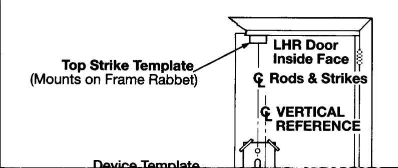
1. Mark Door
Locate and Mark Horizontal and Vertical Reference Centerlines as shown.
LHR door shown preparation is typical for both door hands.
Caution: If device is mounted higher or lower than shown, rod length must change. Lenghten or cut top and
and
39-15/16 (1014)
DOOR
2-3/4
bottom rods as shown on Step 4. LBR - For Less Bottom Rod Devices, omit bottom
latch and strike installation steps and see separate instructions for top latch and strike.
NOTE: Less Bottom Rod (LBR) Devices should not be used where security is a primary concern.
FINISHED FLOOR
Single Door or Pair without Mullion
Measure Gap Write Dimension Here:
& DOOR --
LHR DOOR
& VERTICAL
REFERENCE
HORIZONTAL
REFERENCE
INSIDE FACE
C VERTICAL REFERENCE
2. Prepare Door Frame & Sill
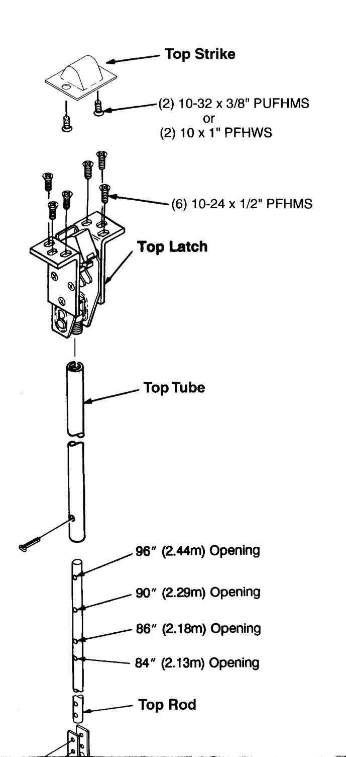
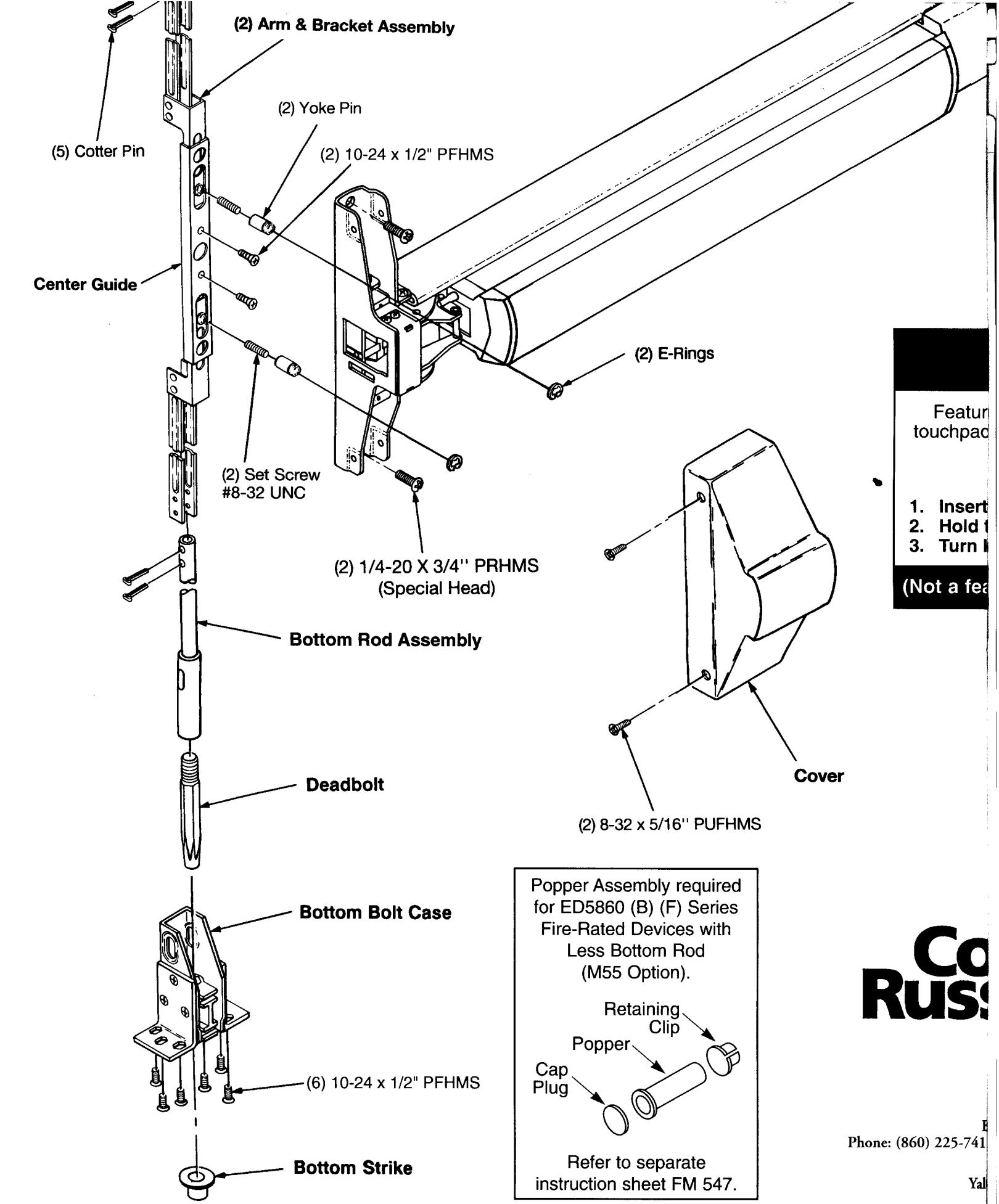
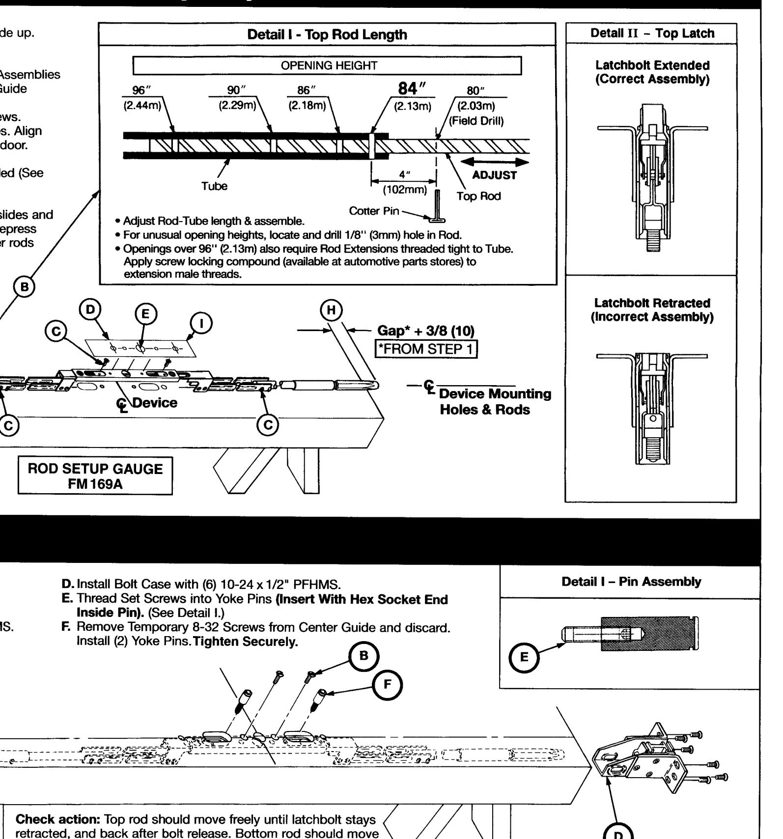
4. Rod Assembly
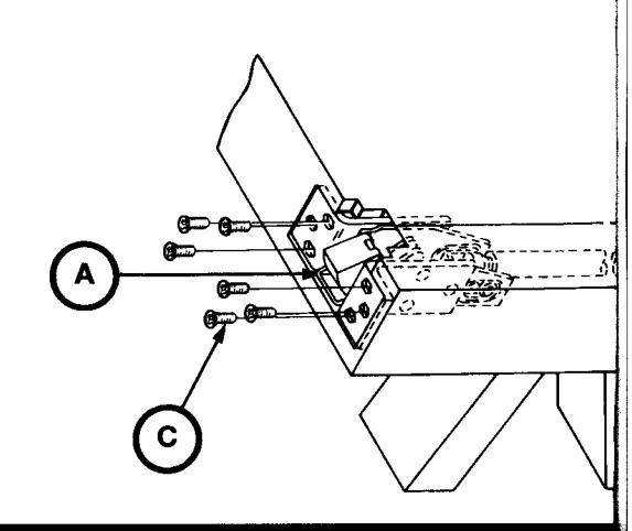
- A. Remove door from opening. Set flat, device (Do not hang until Step 8.)
- B. Set length of Top Rod Assembly (see Detail
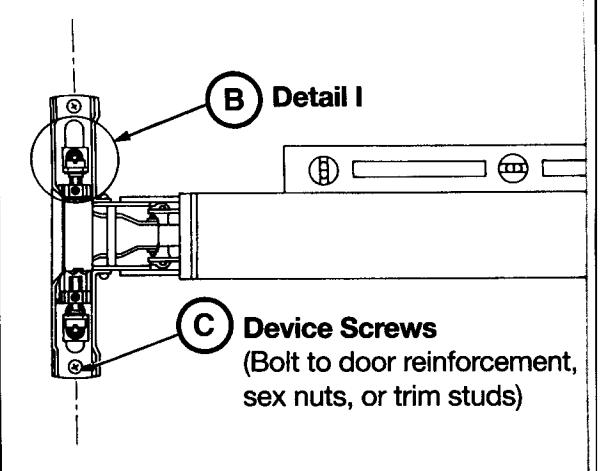
- C. Connect Top & Bottom Rods to Arm/Bracke (2 Cotter Pins each), then connect to Center with temporary 8-32x1/4" PPHMS.
- D. Align Rod Setup Gauge over 2 temporary so
- E. Match Gauge, Yoke & Device (door) centerling Gauge/Yoke holes with holes countersunk o
- F. Set Top Latch in place.
- G. Connect Top Latch. Latchbolt must be exter Detail II).
- H. Set bolt in place.
- I. Remove Rod Setup Gauge. Check that yoke rods move freely and retract bolts correctly. lever behind bolt to extend top latch and low to rest position.
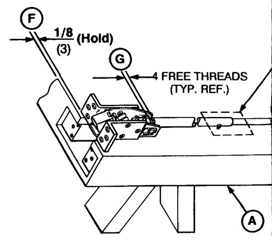
5. Install Rods
- A. Slide Rod Assembly into door.
- B. Fasten Center Channel with (2) 10-24 x 1/2 PFHMS.
- C. Attach Top Latch with (6) 10-24 x 1/2" PFH
6 Install Davice
(F) Series Concealed Vertical Rod Exit Devices
& Preliminary Adjustment
freely up and down, at least 9/16 (14).
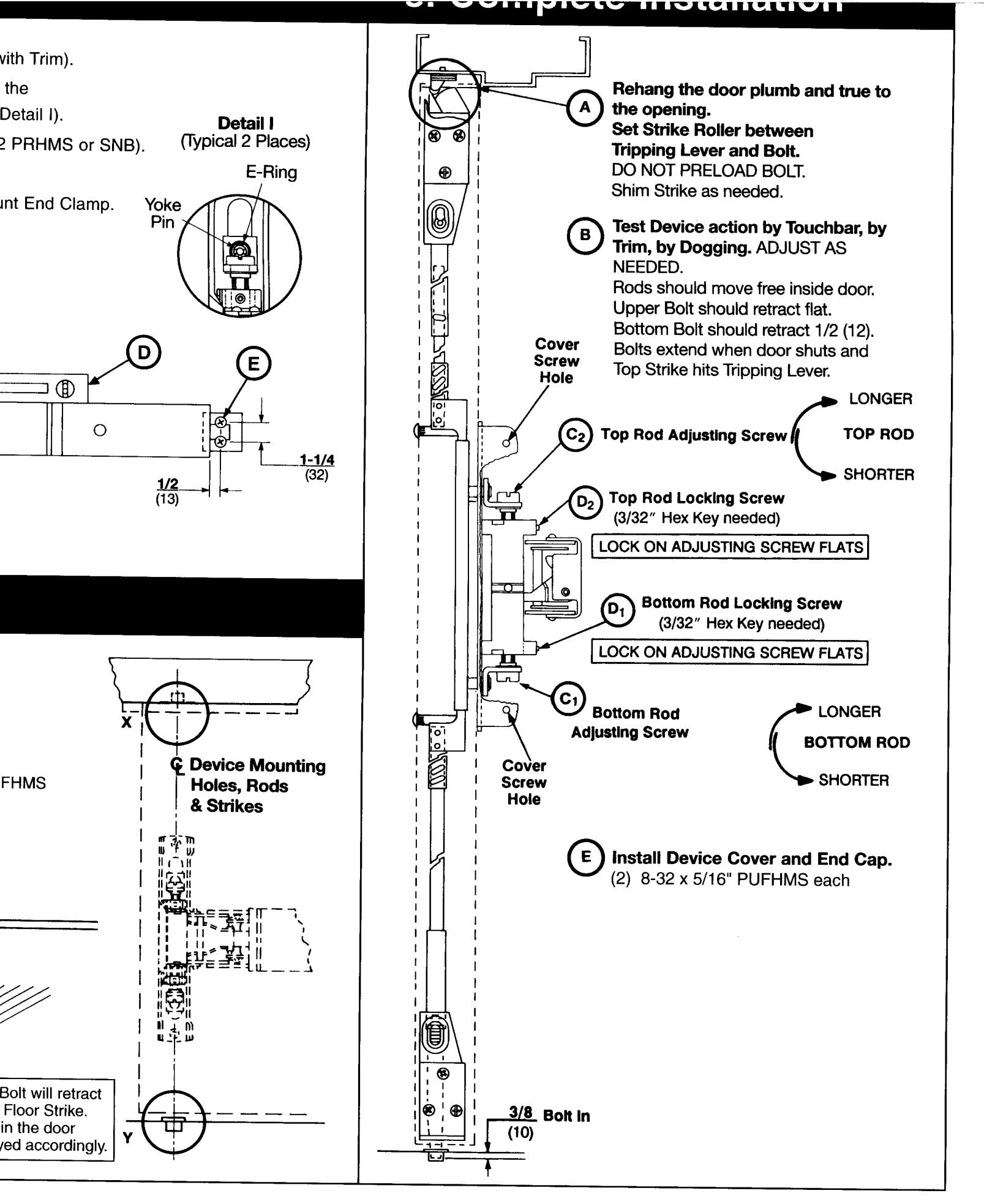
8 Complete Installation
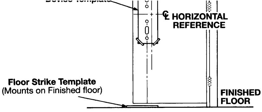
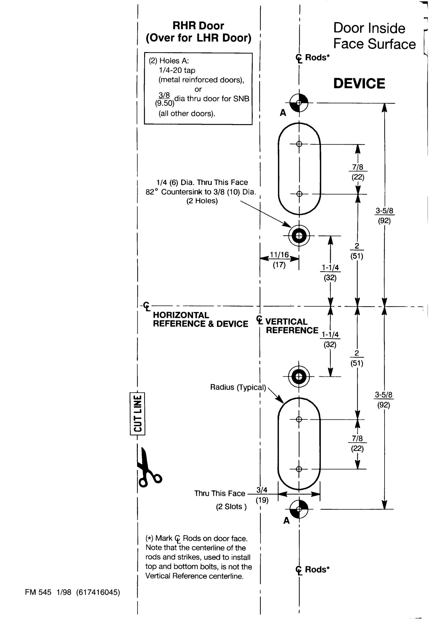
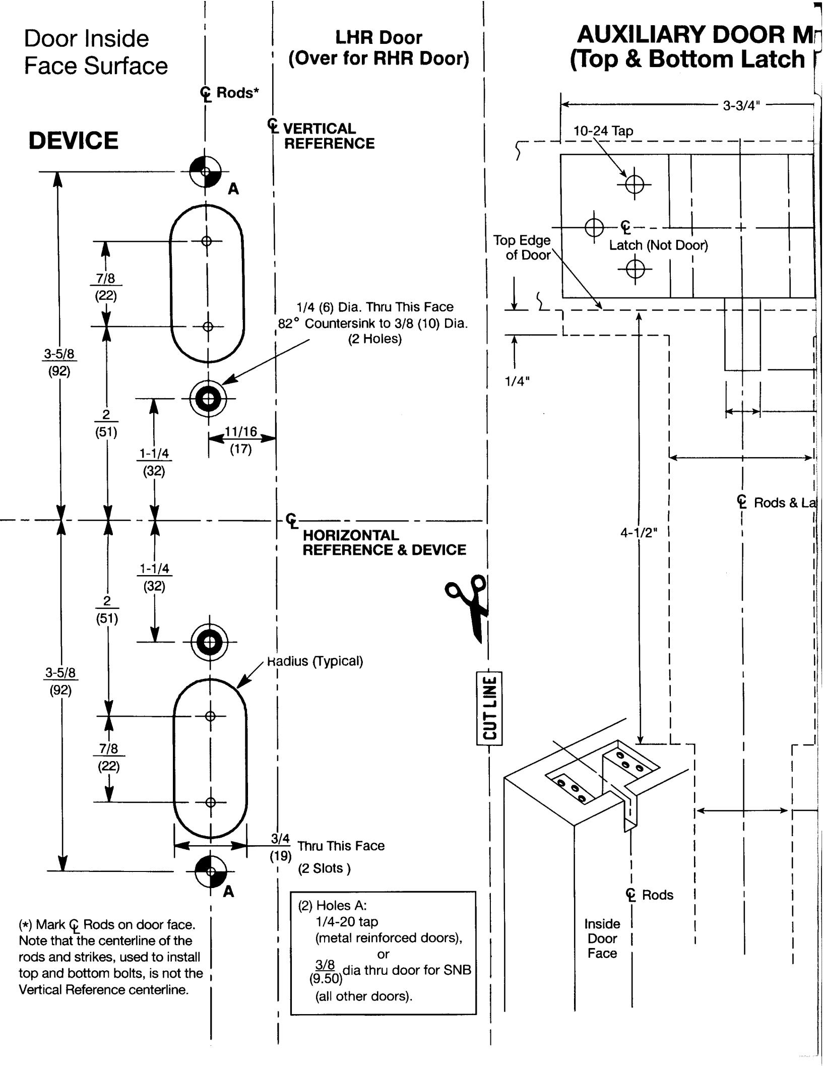
- A. Locate "Device Template" aligning VERTICAL REFERENCE and HORIZONTAL REFERENCE lines on door and template. Tape template to door face.
- B. Extend centerline of Rods and Strikes from "Device Template" to door top and bottom, on door face.
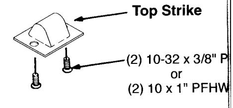
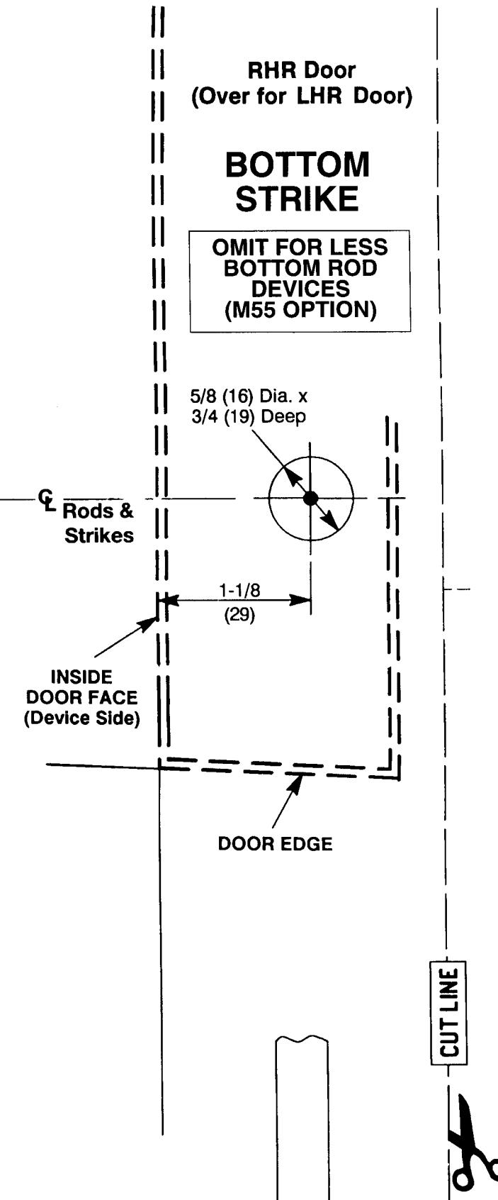
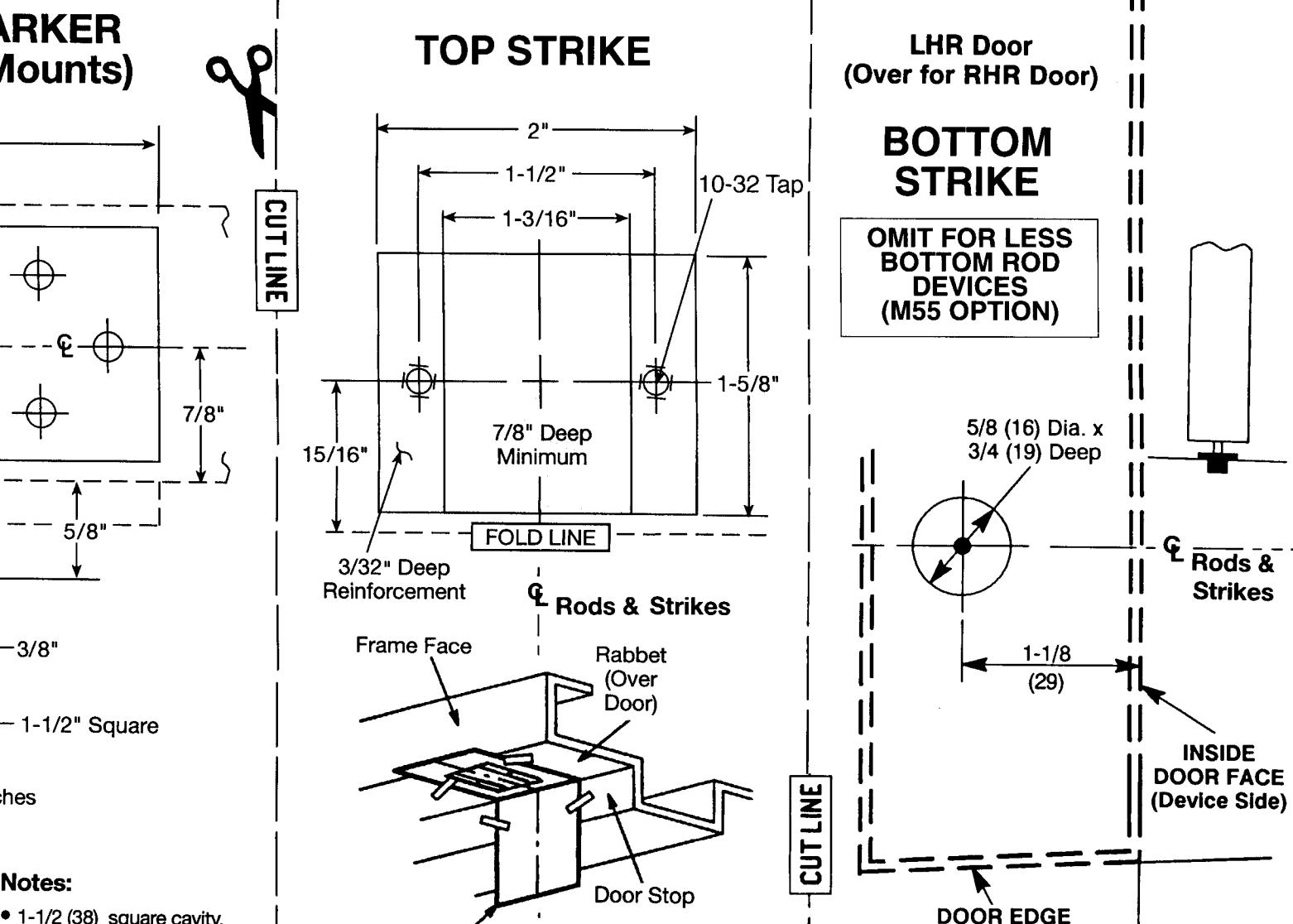
- C. Locate "Top Strike" and "Bottom Strike" templates, aligned with centerline of Rods and Strikes on door. Tape templates in place.
- D. Locate and tape Trim Template to door (See Instructions Packed with Trim).
- E. Spot and prepare holes:
Device and Bolt Case Plates:
Each (2) 1/4-20 Machine Screws*, or
(2) Dia. Sex Nuts & Bolts
(*) Metal reinforced door only.
Top Strike: (2) 10-24 Machine Screws,
NOTE: Third Screw MUST ONLY be used to lock Strike
in final position (Step 8E).
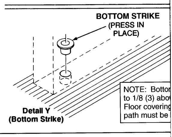
Bottom Strike: dia. deep hole.
Note: Auxiliary door marker is included to verify correct door
preparation. Reinforced doors and frames, with factory made
cutouts, are recommended.
3. Size Device
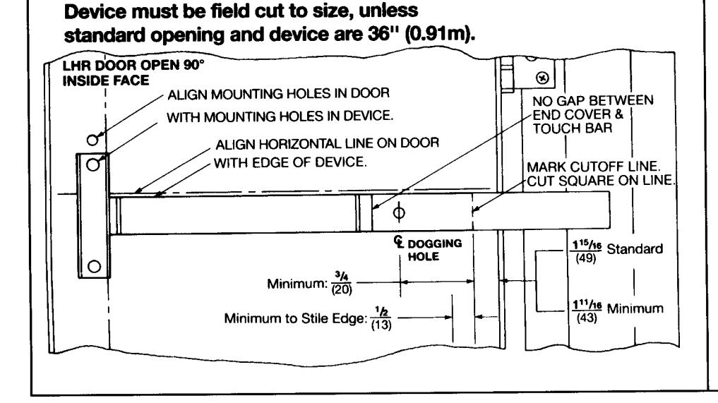
- A. Mount Trim (Follow Instructions Packed)
- B. Set Rod Adjusting Screws Half Way Thre Slider, then Connect Rods to Slider (see
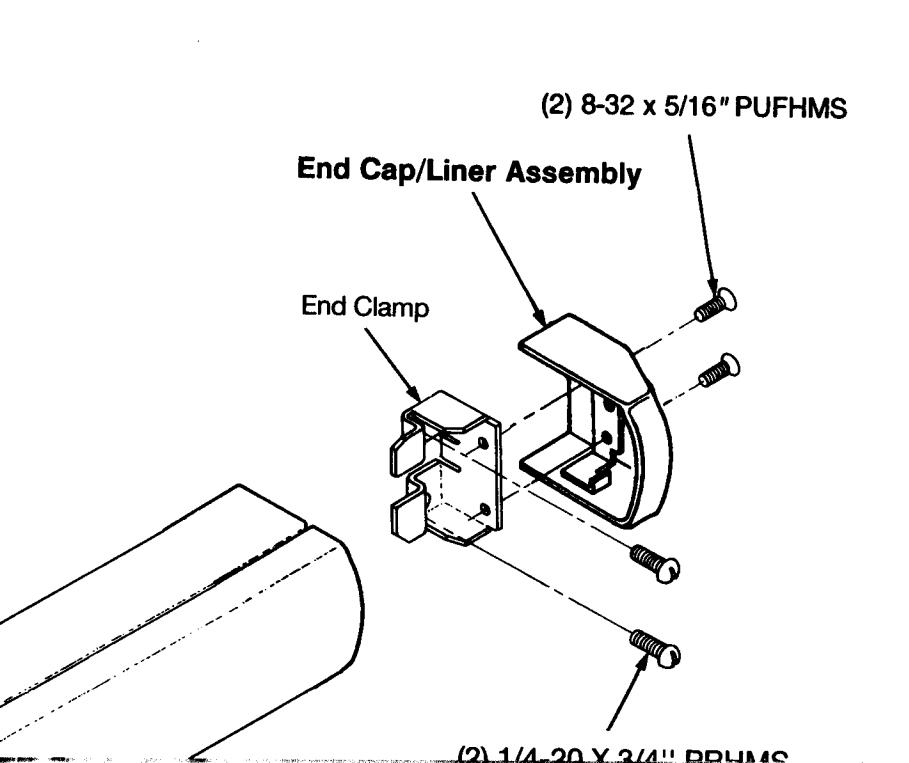
- C. Seat Bar in Place. Fasten Device Head
- D. Set Bar Level. Locate End Clamp Holes
- E. Prepare End Clamp Mounting Holes. Mo (2 # 1/4-20 PRHMS or 3/8/(10) dia. SNB).
7. Install Strikes
Detail X (Upper Strike)

In U.S.:
Corbin Russwin, Inc. 225 Episcopal Road Berlin, CT 06037 USA
Phone: (860) 225-7411 Fax: (860) 828-7266
In Canada:
Yale-Corbin Canada LTD.
3160 Orlando Drive
Mississauga, Ontario, Canada L4V1R5
Phone: (905) 672-6220 Fax: (905) 672-9022
ALIGN WITH DOOR EDGE AND DOOR FACE (DEVICE SIDE)
ED5860 (B) (F) Series Concealed Vertical Rod Exit Devices Installation Template
- 1-1/2 (38) square cavity, centered on rods, is needed to be 4-1/2" deep minimum in top and bottom of door, for full length optional.
- Top and bottom latch holes shown for reference. Position latch in place to locate holes.
- 1" Minimum
Instructions:
STRIKE
MARKER
(Tape as
Shown)
1. Use with Installation Instructions FM 544.
Device
Mounting
& Strikes
Holes, Rods
- 2. For LBR Devices, omit bottom latch and strike in installation steps.
- 3. Less Bottom Rod (LBR) Devices should not be used where security is a primary concern.
- 4. Unreinforced frames (total wall thickness less than , require) that 10-32 blind rivet nuts (by others) be used to bolt strike.
- 5. Dimensions given in inches .
- 6. CAUTION: Office copiers and facsimile machines may change the size of a drawing and make the template inaccurate to use as a door marker. If this is not the original template packed with the device, use only the dimensions written on the template to locate the holes on the door (do not use the template as a door marker).
ED5860 (B) (F) Series Concealed Vertical Rod Exit Devices Installation Template
FM 545 1/98 (617416045)
ALIGN WITH DOOR
EDGE AND DOOR
FACE (DEVICE SIDE)