Corbin Russwin ED5000 Series ED5860(B) Wide Stile CVR Installation Instructions_FM544
Open the original PDF document
View PDF

ED5860 (B) Series
Concealed Vertical Rod
Exit Device
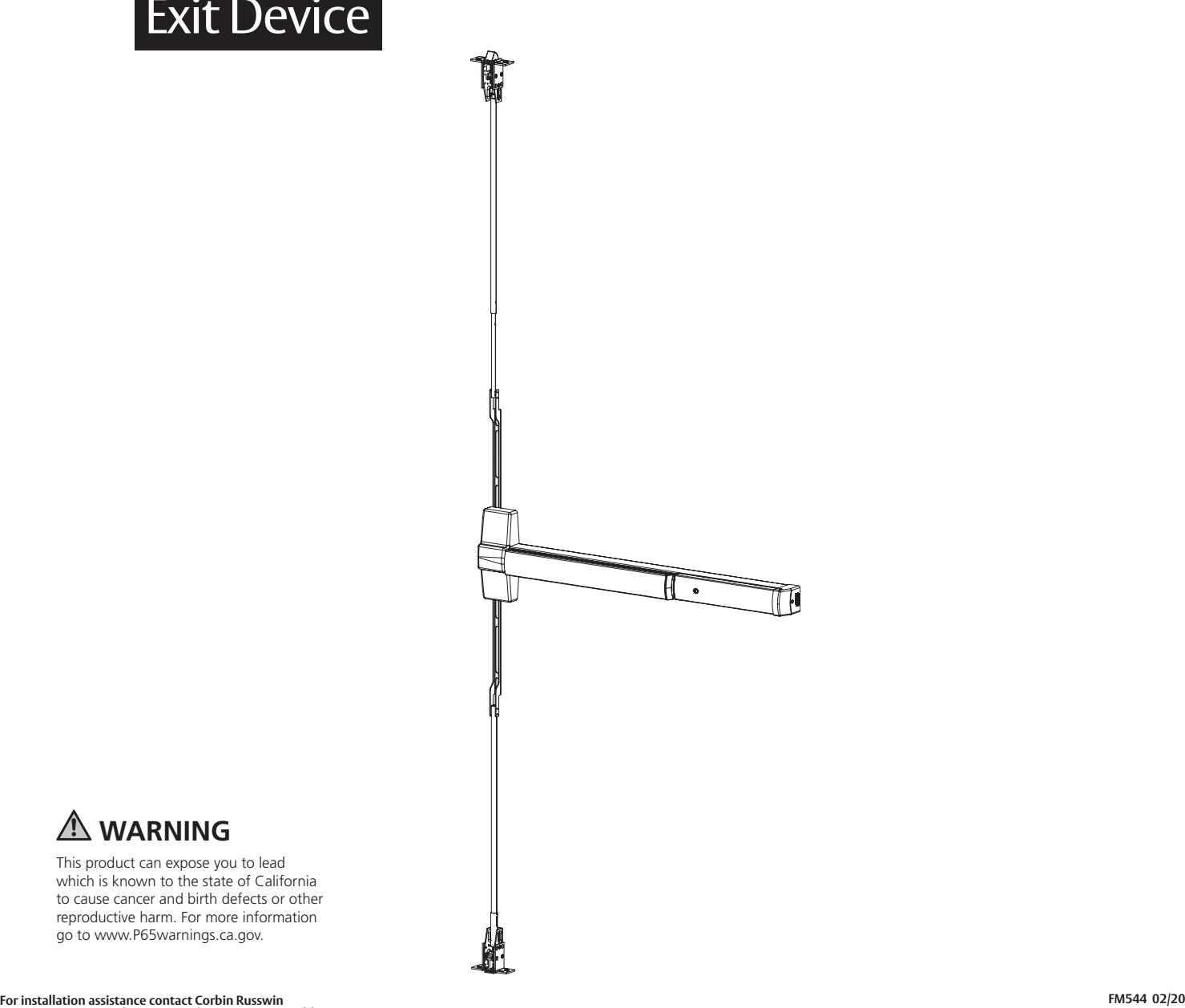

This product can expose you to lead which is known to the state of California to cause cancer and birth defects or other reproductive harm. For more information go to www.P65warnings.ca.gov.
ED5860 (B) Series
Exit Device
Installation Instructions

| TOC | Table of Contents | |
|---|---|---|
| 1 | Package Contents 3 | |
| 2 | Options 4 | |
| 3 | Dogging 4 | |
| 4 | Plastic Installation Template 5 | |
| 5 | Pre-Installation 6 | |
| a | To Change Hands 6 | |
| b | Check Before Starting 6 | |
| c | Mark Door 7 | |
| d | Prepare Door, Frame and Sill 8 | |
| e | Size Device 8 | |
| 6 | Installation 9 | |
| a | Rod Assembly and Preliminary Adjustment 9 | |
| b | Install Rods | 10 |
| c | Install Device | 10 |
| d | Install Strikes | 11 |
| e | Complete Installation | 12 |
| 7 | Maintenance | 14 |

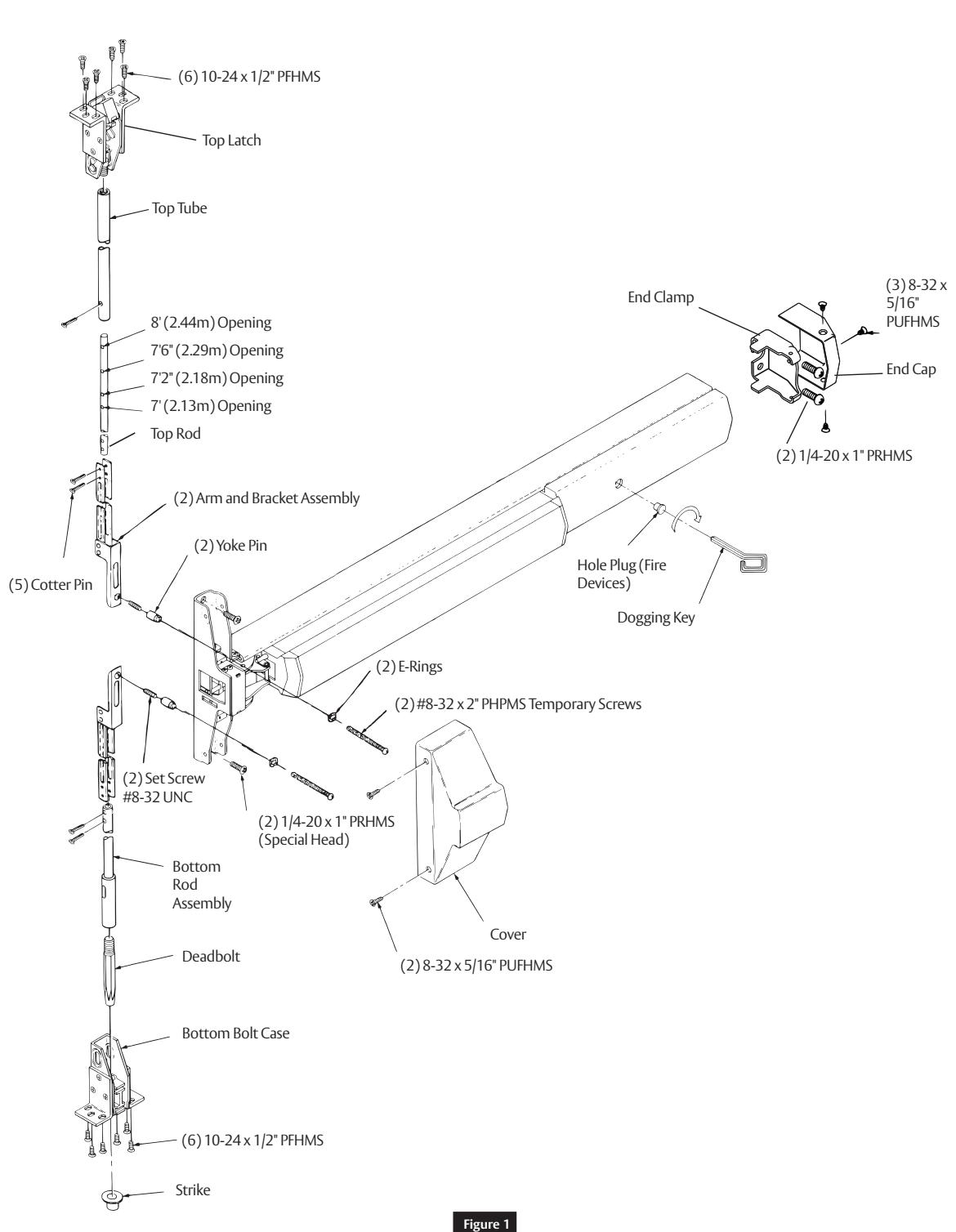
1 Package Contents

2 Options
1/4-20 Sex Nut Option:
- Standard for Fire Rated doors.
- Recommended for wood and unreinforced metal doors.
| Device | Quantity | Size |
|---|---|---|
| All (No Trim) | 4 | |
| All (With Trim) | 2 | 1/4-20 |
Rod Extension Option:
3 Dogging
Dogging is a feature that holds bolts in a retracted position with the touchpad depressed for push-pull door operation.
Note:
Dogging is not a feature of fire-labeled devices.
To Dog Device:
- 1. Insert dogging key.
- 2. Depress and hold the touchbar.
- 3. Turn key 1/4 turn clockwise.
Important:
Device is packed ready for any compatible trim.

4 Plastic Installation Template
For use in conjunction with instruction sheets packed with exit device.
Holes and slots are identified below by exit device series and trim. Prep door and frame for only those features required for the exit device being installed.

5 Pre-Installation
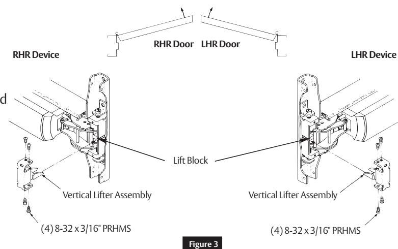
a To Change Hands
- 1. Remove four (4) screws and vertical lifter assembly.
- 2. Rotate device 180˚ to opposite orientation.
- 3. Insert vertical lifter assembly and reinstall screws.
Note:
Lifter must fit under lift block as shown. ( Figure 3)
b Check Before Starting
Doors and frames with walls having a structural thickness (metal skin plus reinforcement) to engage less than three (3) full screw threads are considered unreinforced.
Unreinforced Doors:
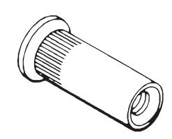
Use SNB (sex nuts and bolts) or Blind Rivet Nuts. (Figure 4 )
Unreinforced Frames:
Use Blind Rivet Nuts. (Figure 5 )
Recommended fasteners for unreinforced openings may not be supplied by Corbin Russwin.
- Door must swing freely.
- Door must not be warped.
- Door must not bind.
- Door must not sag.
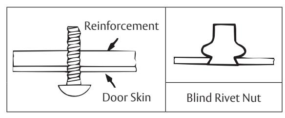
Figure 4
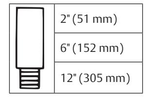
- • Minimum Door Stile: 4-1/2" (114mm)
- Door and frame must meet structural and dimensional specifications on exit device template(s) for door and frame preparation.
- Device must seat flush on door surface. To clear raised molding, consult the factory.
Figure 5

5 Pre-Installation (continued)
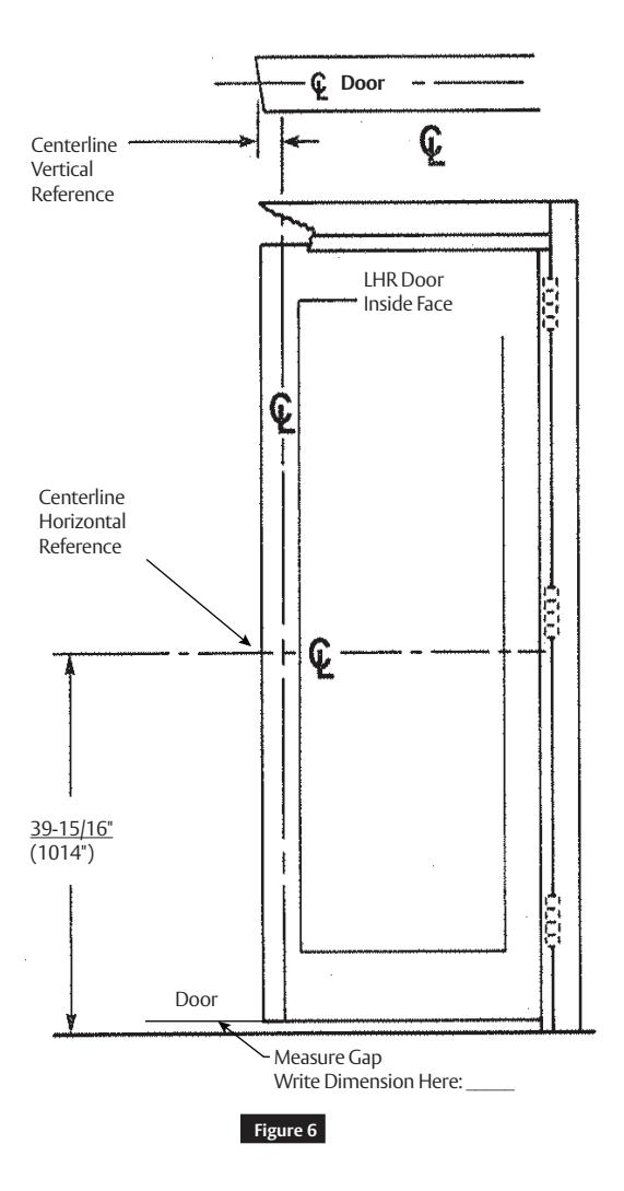
c Mark Door
Single Door or Pair without Mullion:
- Locate and mark horizontal and vertical centerlines as shown. (Figure 6)
- LHR door shown. Preparation is typical for both door hands. (Figure 6)
Caution:
If device is mounted higher or lower than shown, rod length must change. Lengthen or cut top and bottom rods as shown in " Rod Assembly and Preliminary Adjustment " on page 9 .
Note:
Bottom bolt will retract to 1/8" (3mm) above floor strike. Floor covering in the door path must be laid accordingly.

5 Pre-Installation (continued)
d Prepare Door, Frame and Sill
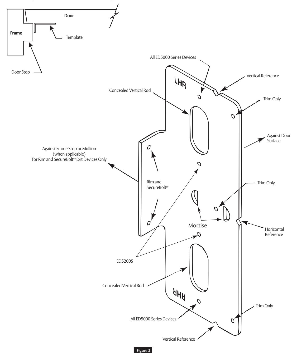
- 1. Locate device paper template aligning VERTICAL REFERENCE and HORIZONTAL REFERENCE lines on door and template. Tape template to door face. (Figure 7)
- 2. Extend centerline of rod and strikes from device paper template to door top and bottom, on door face.
- 3. Locate top strike and bottom strike templates, aligned on centerline of rods and strikes on door.
- 4. Tape templates in place and mark holes. (Figure 7 )
Note:
Auxiliary door marker is included to verify correct door preparation. Reinforced doors and frames, with factory made cutouts, are recommended.
- 5. Locate and tape trim template to door. (See instructions packed with trim)
- 6. Mark and prepare holes per installation template.
Device and Bolt Case Plates: Use two (2) 1/4-20 machine screws for metal reinforced doors OR two (2) 3/8" (10) diameter sex nuts and bolts for each.
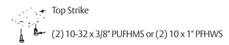
Top Strike: Use two (2) 10-24 machine screws.
Note:
Third screw MUST ONLY be used to lock strike in final position (See "Rod Assembly and Preliminary Adjustment " Step 7).
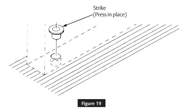
Bottom Strike: 5/8" (16) diameter x 3/4" (19) deep hole.
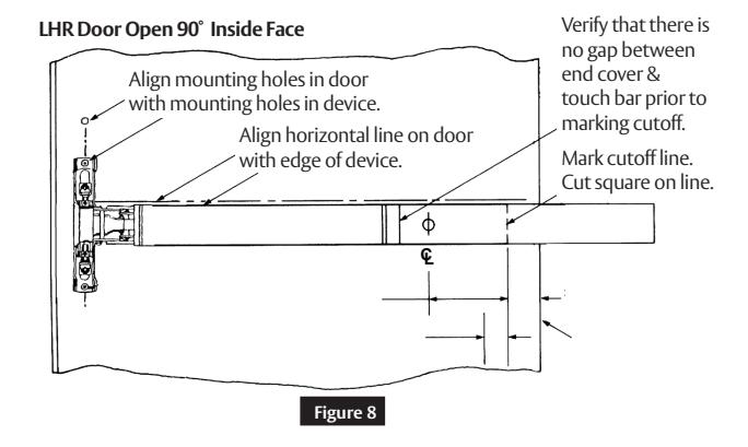
e Size Device
Device must be field cut to size, unless standard opening and device are 36" (0.91m). ( Figure 8)
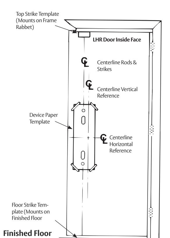
Figure 7

6
Installation
a
Rod Assembly and Preliminary Adjustment
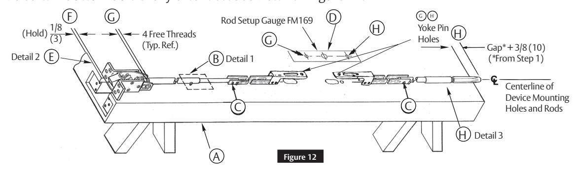
- 1. Remove door from opening.
- Set flat; device side up. Do not hang door until you "Complete Installation" on page 12. (Figure 12-A)
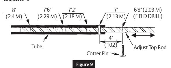
- 3. Set length of top rod assembly. See Detail 1 Figure 9; Figure 12-B.
- Connect top and bottom rods to arm/bracket assemblies using two (2) cotter pins each. (Figure 12-C)
- 5. Align rod setup gauge over device cutouts and centerlines. (Figure 12-D)
- 6. Tape gauge to door face.
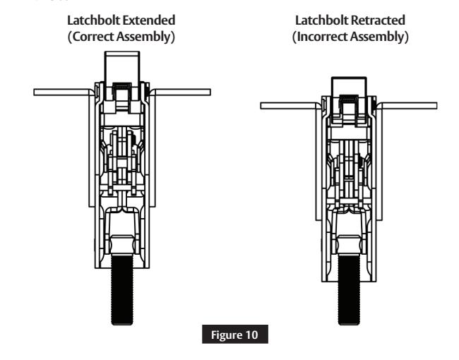
- 7. Connect top latch to rod assembly. Latchbolt must be fully extended. See Detail 2 Figure 10; Figure 12-E.
- 8. Set top latch assembly in place on door. Maintain 1/8" (3) location from top of door as shown. (Figure 12-F)
- 9. Align yoke pin holes in arm and bracket assembly with alignment hole in rod setup gauge. (Figure 12-G)
- 10. Adjust top latch and rod assembly for proper alignment.
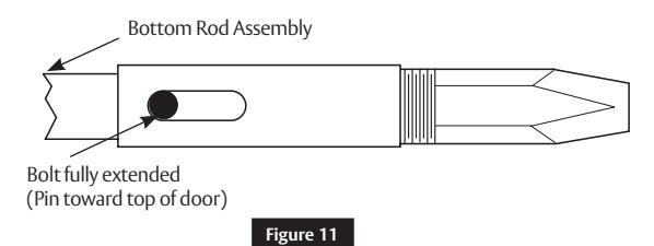
- Thread deadbolt into bottom rod assembly. Set bottom rod assembly in place on door. (Figure 12-H)
- 12. Align yoke pin hole in bottom arm and bracket assembly with alignment hole in rod setup gauge.
- 13. Adjust bottom bolt for proper length.
Detail 1
Detail 2
Detail 3
NOTE
Be certain bottom bolt is fully extended. See Detail 3 - Figure 11.
FM544 02/20
9

6 Installation (continued)
b Install Rods
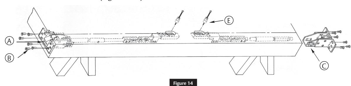
- 1. Slide rod assemblies into door. (Figure 14- A)
- 2. Attach top latch with six (6) #10-24 X 1/2" PFHMS. (Figure 14- B)
- 3. Install bottom bolt case with six (6) #10-24 X 1/2" PFHMS. (Figure 14- C)
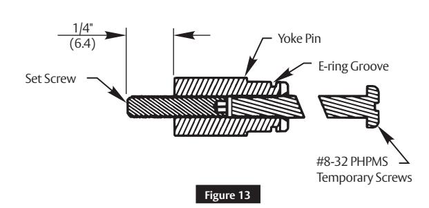
- 4. Thread set screw into yoke pins (Insert with hex socket end inside pin).
- 5. Thread #8-32 x 2" PHPMS screws into slotted end of yoke pins, until seated to hex head set screw. See Detail 1 - Figure 13 .
- 6. Install two (2) yoke pin assemblies into arm and bracket assemblies. (Figure 14- E)
Detail 1
c Install Device
- 1. Mount trim when required. (Follow instructions packed with trim.)
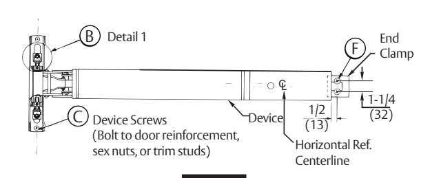
- 2. Seat device in place. (Figure 15 -B)
- 3. Connect device to arm and bracket assemblies using temporary screws to position yoke pins in latch head.
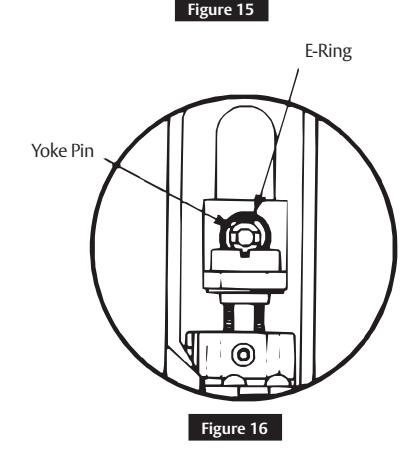
- 4. Install e-ring into yoke pin grooves.
- 5. Fasten device latch head using two (2) 1/4- 20 PRHMS or 3/8" (10) dia. SNB. ( Figure 16) Remove temporary screws.
Note:
Be certain to retighten yoke pins after removal of temporary screws.
- 6. Center end of device on horizontal reference line of door.
- 7. Using end clamp as a template, locate end clamp mounting holes.
- 8. Prepare end clamp holes and mount end clamp using two (2) 1/4-20 PRHMS or 3/8" (10) SNB. ( Figure 15- F)

6 Installation (continued)
d Install Strikes
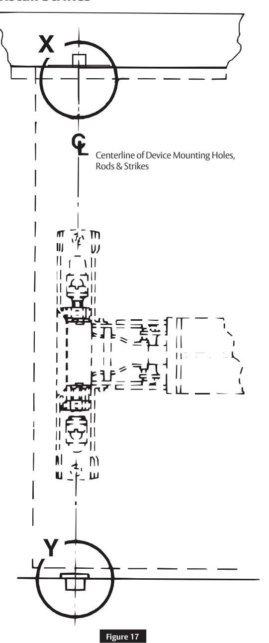
Detail X:
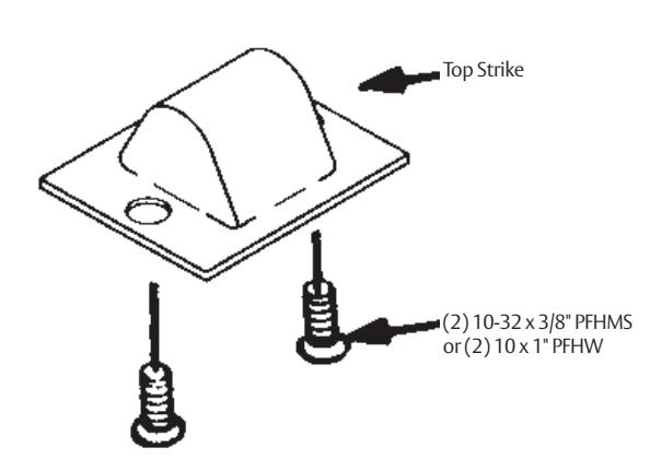
Figure 18
Detail Y:
Note:
Bottom bolt will retract to 1/8" (3mm) above floor strike. Floor covering in door path must be laid out accordingly.

6 Installation (continued)
e Complete Installation
- 1. Rehang door plumb and true to opening.
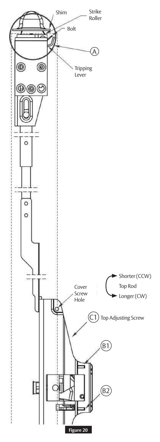
- 2. Set strike roller between tripping lever and bolt. DO NOT PRELOAD BOLT. ( Figure 20 )
Note:
Rods should move freely inside door. Bolts extend automatically and should deadlock when door closes and tripping lever hits frame. Top bolt should retract flat. Bottom bolt should travel 1/2" (13 mm) and engage 3/8" (9.5 mm) into strike in down position without dragging on floor surface in up position.
- 3. Test device action by touchbar, by trim, and by dogging. Adjust as needed.
-
4. Adjust rod for proper bolt throw:
- a. Use 3/32" (2.4 mm) hex wrench to remove set screws B1 and B2. (Figure 20)
- b. Adjust top rod first with adjusting screw C1. (Figure 20)
- c. With device in dogged position (panic devices) or touchbar fully depressed (fire devices), adjust top rod so that top latchbolt is flush and hold back feature is engaged.
- d. Lengthen top rod an additional 1/2 turn for proper latchbolt positioning.
Note:
- If adjusting screws bottom out before proper device operation, door and device must be removed so larger adjustments may be made by threading rod in or out, or by moving cotter pin to different hole in rod.
- • To avoid thread damage and provide positive locking, be sure set screws engage flats on adjusting screws.

6
Installation (continued)
e
Complete Installation (continued)
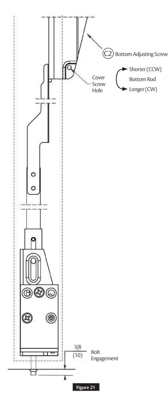
- e. Adjust bottom rod with adjusting screw C2. (Figure 21)
- f. With top latch retracted in hold back position, and touchbar dogged or fully depressed, adjust bottom rod so that deadbolt clears strike by 1/16" (1.6 mm). The bottom rod should be in position in active case with square head of connector hanging in the guide.
- g. Check device operation by opening and closing the door. An additional minor adjustment may be required for full retraction and correct strike engagement. Top latch should consistently go into holdback with gentle (full) press of touchbar.
Note:
To avoid thread damage and provide positive locking, be sure set screws engage flats on adjusting screws.
- 5. After acceptable device function, install third screw in top strike to lock strike in position with 10-24 x 3/4" PFHMS.
- 6. Install device cover and end cap with (2) 8-32 PFHMS each.
ED5860 (B) Series
Exit Device
Installation Instructions

7 Maintenance
- Periodically remove covers and coat mechanisms with an appropriate lubricant. This is particularly essential in corrosive environments for proper product function.
- Check mounting fasteners periodically. Re-tighten if found loose. Apply threadlocking compound or change part fasteners if screws continue to back out.
- Periodic checks (and adjustments) or rods may be required to compensate for changes in the opening (e.g. door sagging).
ED5860 (B) Series
Exit Device
Installation Instructions

15

Corbin Russwin, Inc. 225 Episcopal Road Berlin, CT 06037 USA Phone: 800-543-3658 Fax: 800-447-6714 www.corbinrusswin.com