Corbin Russwin ED5000 Series ED5400(A), ED5470(B) Wide Stile SVR Installation Instructions_FM164
Open the original PDF document
View PDF

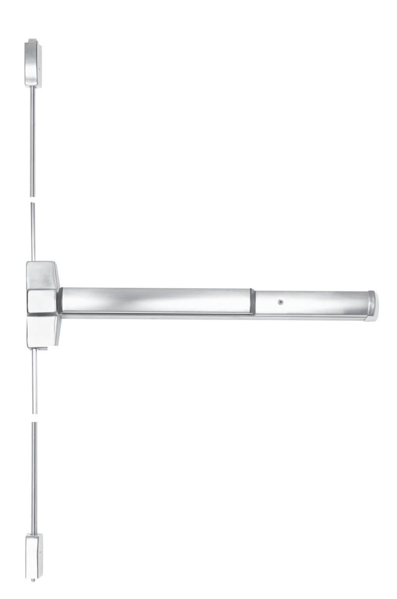
Surface Vertical Rod
ED5400 (A) Series & ED5470 (B) Series
Exit Devices

This product can expose you to lead which is known to the state of California to cause cancer and birth defects or other reproductive harm. For more information go to www.P65warnings.ca.gov.
Exit Devices
Installation Instructions

Exit Devices
Installation Instructions

| TOC | Table of Contents |
|---|---|
| 1 | General Information4 |
| a | Change Hands6 |
| b | 1/4-20 Sex Nut Option6 |
| c |
Rod Extension Options
6 |
| d | Maintenance7 |
| e | Shim Kit Option7 |
| 2 |
Preparation
7 |
| a | Check Before Starting7 |
| b | Mark Door8 |
| c | Prepare Door, Frame, and Sill8 |
| d | Clear Raised Door Molding9 |
| e | Size Device9 |
| 3 | Installation 10 |
| a | Install Device 10 |
| b | Set Latches, Strikes, and Guides 10 |
| c | Prepare Rods 11 |
| d | Complete Installation 12 |
| 4 | Plastic Installation Template for ED5000 Exit Devices 13 |
| 5 | Door Templates for ED5000 Exit Devices 13 |
Exit Devices
Installation Instructions

1 General Information
Top bracket and strike required for ED5470.
Popper assembly required for ED5470 (B) Series Fire-Rated Devices with Less Bottom Rod (M55 Option).

Note
All dimensions are in inches unless otherwise noted.
or in part without the express written permission of ASSA ABLOY Access and Egress Hardware Group, Inc. is prohibited.
Exit Devices
Installation Instructions

1 General Information (cont.) (2) 1/4-20 X 1" PPHMS (Metal Door) or (2) #14 x 1-1/2" PPH"AB"SMS (Wood Door) Cover (3) 10-24 x 1/4" (6mm) PPHMS Top Latch (Panic & Fire Label) Bottom Bolt Case Panic & Fire Label Top Rod (2) 1/4-20 X 3/4" PFHMS (Metal Door) or (2) #14 x 1-1/2" PFH"AB"SMS (Wood Door) Bottom Rod Assembly Deadbolt 790 Strike Bolt Case Cover (2) 8-32 x 1/4" (6mm) PFHMS Bottom Mounting Plate (2) #8 x 1/2" (13mm) PRH"AB"SMS Guide Cover Rod Guide (2) #6 x 3/8" (10mm) PTH"AB"SMS Roll Pin Latch Cover 791 Strike Strike Plate Shim (2) Supplied (3) 10-24 x 3/4" (19mm) PFHMS Top Mounting Plate Hole Plug (Fire Label Devices) Rod Guide (2) 8-32 x 5/16" (8mm) PFHUMS Guide Cover (3) 10-24 x 1/4" (6mm) PPHMS (2) 8-32 x 1/4" (6mm) PFHMS (2) #6 x 3/8" (10mm) PTH"AB"SMS Top Rod Connector (2) #8 x 1/2" (13mm) PRH"AB"SMS (2) 1/4-20 X 3/4" PFHMS (Metal Door) or (2) #14 x 1-1/2" PFH"AB"SMS (Wood Door) Dogging Key (3) 8-32 x 5/ PFHUMS (2) 1/4-20 X 1" PPHMS (Metal Door) or (2) #14 x 1-1/2" PPH"AB"SMS (Wood Door) End Clamp End Cap For metal, composite, and wood doors of either hand Bottom rod and latch components not supplied with less bottom rod devices (LBR), M55 Option. Outside Trim Device is packed ready for any compatible trim. Dogging Feature to hold bolts retracted and touchpad depressed, for push-pull door operation. To Dog Service 1. Insert dogging key.
2. Depress and hold touchbar. 3. Turn key 1/4 turn clockwise.
(Not a feature of fire labeled devices.)

1 General Information (cont.)
a Change Hands
Remove four (4) screws and vertical lifter assembly. Rotate device to opposite hand (180˚). Insert lifter assembly under lift block and re-install screws.
Note
Lifter must fit under lift block as shown. (Figure 1)
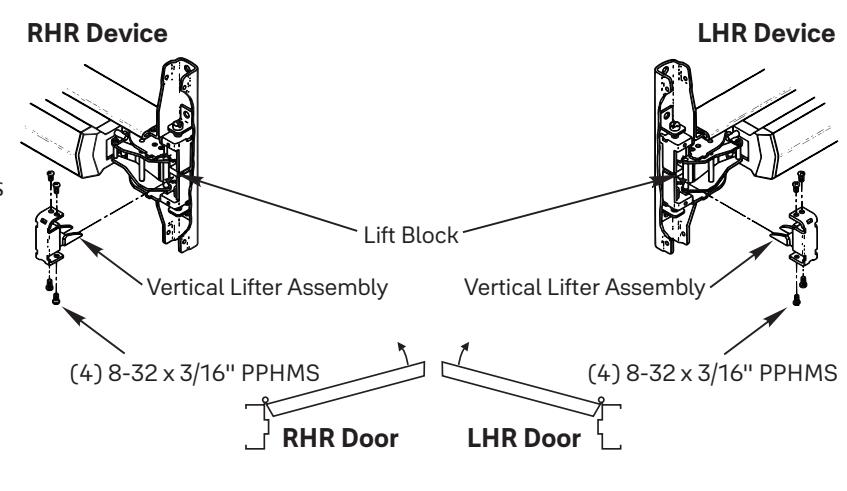
Figure 1
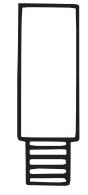
b 1/4-20 Sex Nut Option
Recommended for wood composite or unreinforced metal doors. (Figure 2)
| Device | Quantity | Size |
|---|---|---|
| No trim | 8 | |
| With trim | 6 | 1/4 - 20 |
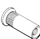
Figure 2
Note Standard for Fire Rated doors.
c Rod Extension Options
- 2" (51 mm)
- 6" (152 mm)
- 12" (305 mm)
- 24" (610 mm)
- (Specify device finish)

1 General Information (cont.)
d Maintenance
- 1. Periodically remove covers and coat mechanisms with a silicone-based lubricant. This is particularly required in corrosive environments for proper product function.
- 2. Check mounting fasteners periodically. Retighten if found loose. Apply screw locking compound (available at automotive part stores) or change part fasteners if screws continue to back out.
- 3. Periodic checks (and adjustments) of strikes are required to compensate for changes in the opening (e.g. door sagging).
e Shim Kit Option
697F348 Black Finish
- Kit consists of (2) Latch Head Shims (Device Cover seats on shim) and (2) End Clamp Shims (End Cap seats on shim), (2) Top and Bottom Latch Shims (Bolt Case Mounting Plates seat on shim), and (4) Rod Guide Shims.
- Each shim is 1/8" (3.2 mm) thick. More than two shim thicknesses 1/4" (6.4 mm), require longer device mounting screws (not included).
2 Preparation
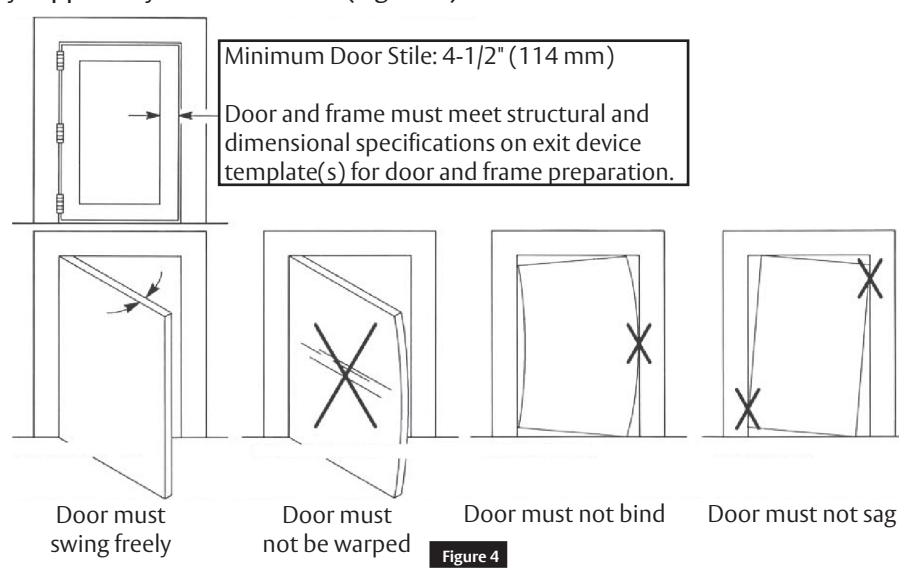
a Check Before Starting
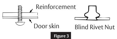
Unreinforced Doors or Frames (Figure 4)
- Doors and Frames with walls having a structural thickness (metal skin plus reinforcement or solid hardwood) to engage less than (3) full screw threads are considered unreinforced.
- Unreinforced Doors: Use SNB (sex nuts and bolts).
- Unreinforced Frames: Use Blind Rivet Nuts.
- Recommended fasteners for unreinforced openings are not necessarily supplied by Corbin Russwin (Figure 3).

Single Door or Pair Without
Door
LHR Door Inside Face
2-3/4" (70 mm)
2 Preparation (cont.)
b Mark Door
Locate and mark horizontal and vertical centerlines as shown. (Figure 5)
LHR door shown. Preparation is typical for both door hands. Vertical reference
Caution
If device is mounted higher or lower than shown, rod length must change. Lengthen or cut top and bottom rods as shown in Step 3c.
LBR
For ED5470 Series Less Bottom Rod Devices, skip bottom latch and strike installation steps and see separate instructions for ED5470 Series top latch and strike.
Note
Less Bottom Rod Devices should not be used where security is a primary concern.
Figure 5 Measure Gap Write Dimension here: XXXX" Door 39-15/16" (1014 mm) Horizontal reference Finished floor Mullion
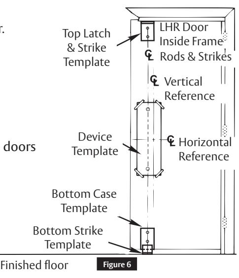
c Prepare Door, Frame, and Sill
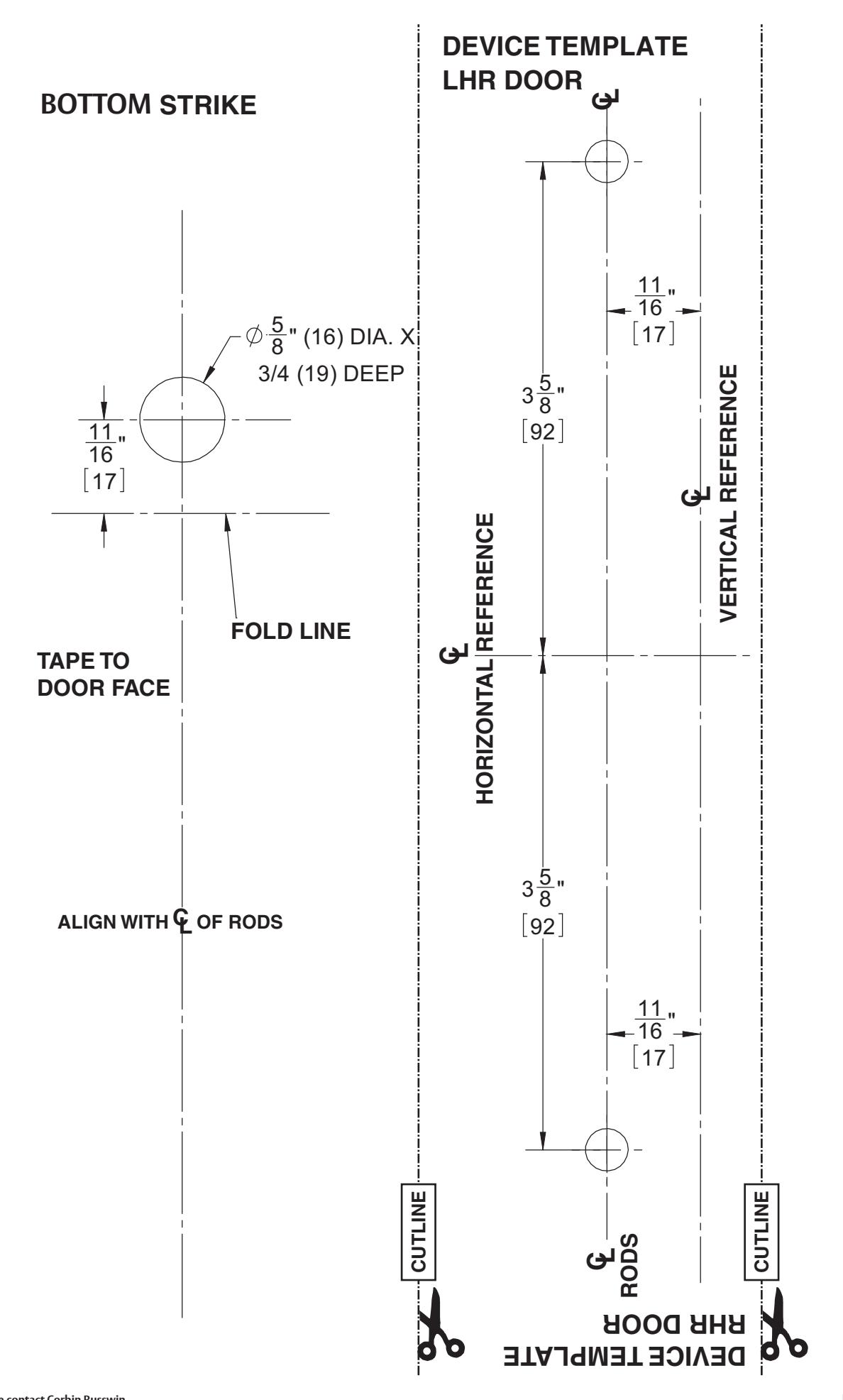
- A. Locate Device Template aligning VERTICAL REFERENCE and HORIZONTAL REFERENCE lines on door and template. Tape template to door face. (Figure 6)
- B. Extend centerline of Rod and Strikes from Device Template to top and bottom of door.
- C. Locate Top Latch/Strike, Bottom Case, and Bottom Strike templates, aligned on centerline of Rods and Strikes on door. Tape templates in place and mark holes.
- D. Locate and tape Trim Template to door (see instructions with Trim).
-
E. Mark and prepare holes per installation template:
- Device and Bolt Case Plates:
Each: (2) 1/4-20 Machine Screws for metal reinforced doors OR (2) 3/8" (10 mm) Dia. Sex Nuts & Bolts.
- Top Strike: ED5400 Series: (2) 10-24 Machine Screws, or (2) #10 Wood Screws. ED5470 Series: (4) 10-24 Machine Screws.
- Bottom Strike: 5/8" (16 mm) Dia. 3/4" (19 mm) Deep hole.
FM164 8/22
8

2 Preparation (cont.)
d Clear Raised Door Molding
Device must seat flush on door surface or on the shims that keep it parallel to door face. (Figure 7)
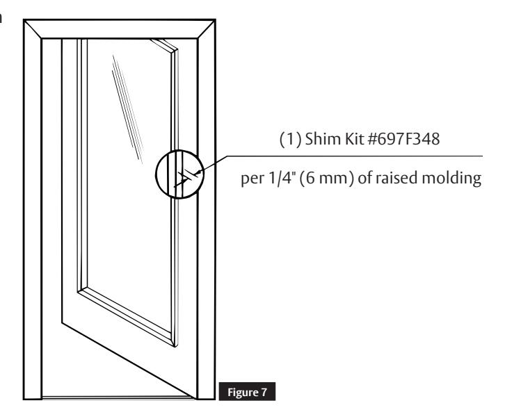
Longer mounting screws are needed when more than (2) shims of 1/8" thick are used. See Shim Kit Option in Step 1e.
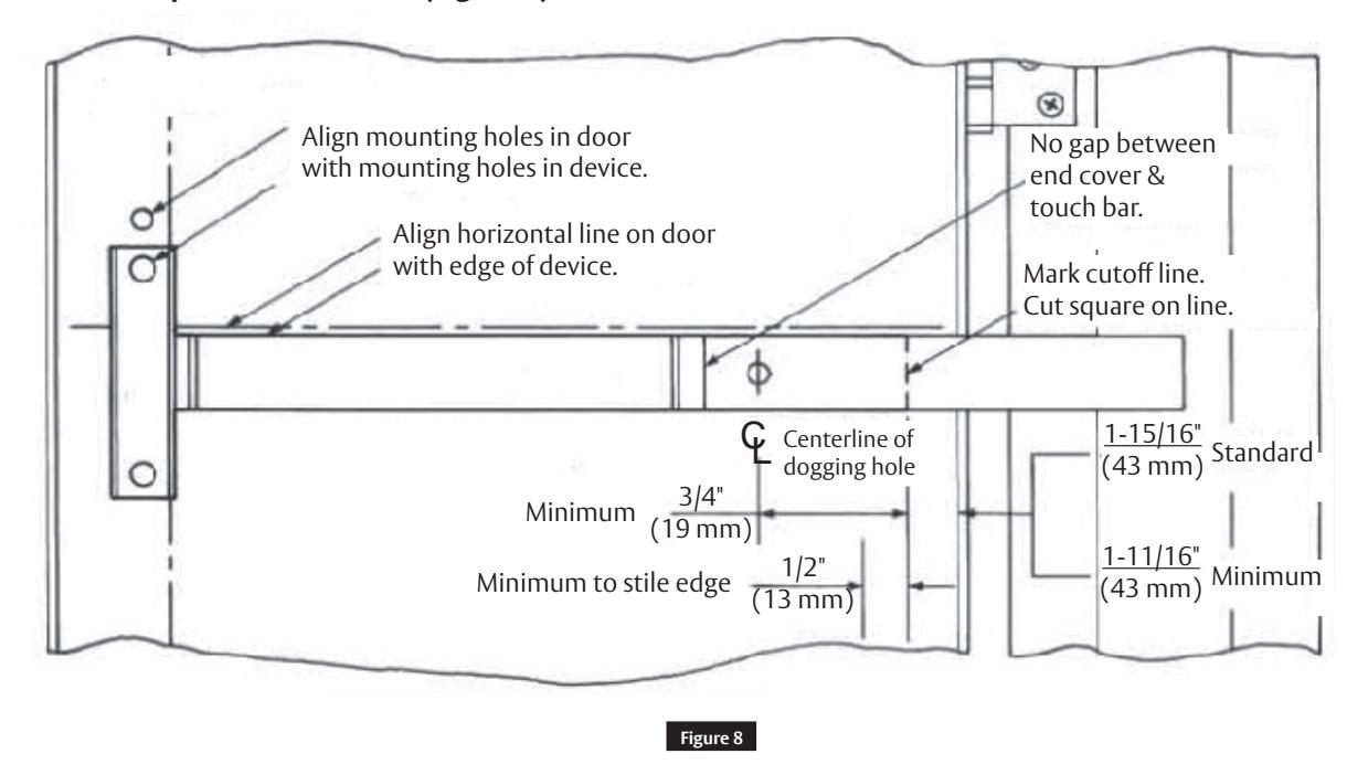
e Size Device
Device must be field-cut to size unless standard opening and device are 36" (0.91 m).
LHR Door Open 90° Inside Face (Figure 8)
Exit Devices
Installation Instructions

3 Installation
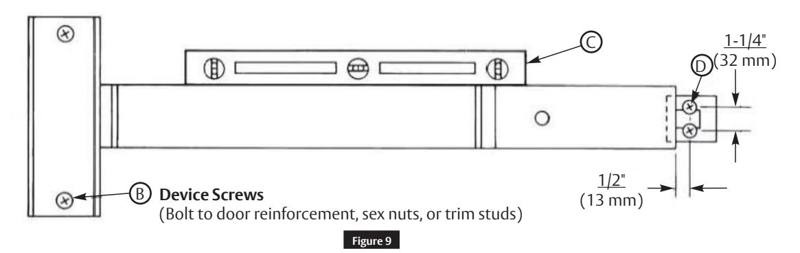
a Install Device
- A. Mount trim (Follow instructions with trim).
- B. Seat bar in place. Fasten device head (2 PRHMS or SNB). (Figure 9)
- C. Set bar level. Locate end clamp holes.
- D. Prepare end clamp mounting holes. Mount end clamp (2 #1/4-20 PRHMS or 3/8" (10 mm) dia. SNB).
-
E. Check slide action (Slide travel = 9/16" (14 mm)
- Depress touchbar (slide should move up). Release touchbar (slide should fall back to original rest position).
- Activate trim (slide should move up). Release trim activator (slide should fall back to rest position).
- NOT FOR FIRE DEVICES Depress touchbar, turn dogging key clockwise (bar must remain depressed, slide must remain in up position). Turn dogging key counterclockwise (bar should extend, slide should fall back to rest position).
- F. Tighten all mounting screws.
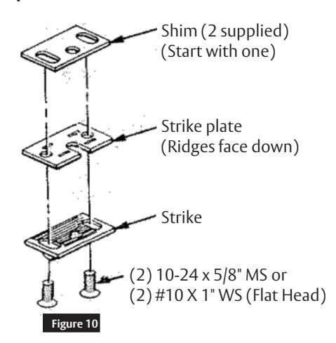
b Set Latches, Strikes, and Guides
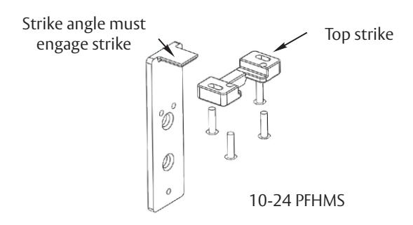
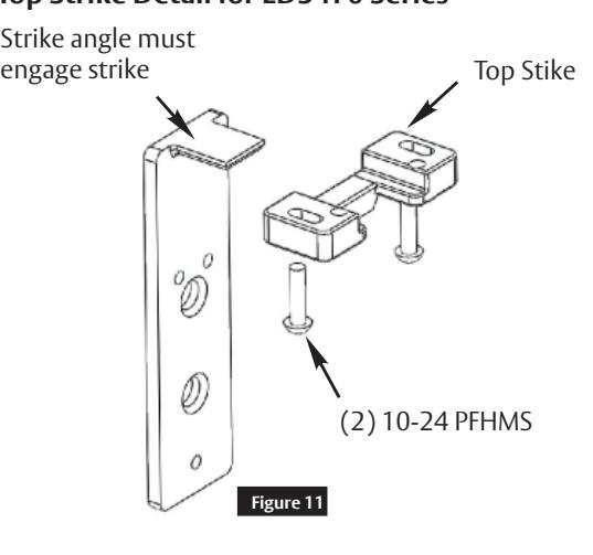
Top Strike Detail for ED5400 Series
Top Strike Detail for ED5470 Series
FM164 8/22
Exit Devices
Installation Instructions

3 Installation (cont.)
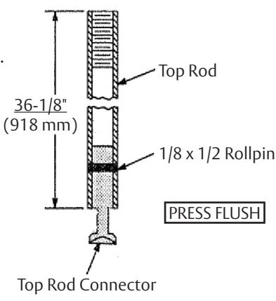
c Prepare Rods
Top Rod (Figure 12)
• Ready for 84" (2134 mm) Openings
Openings Under 84 (2134)
For top rod cutoff length, deduct Opening Height from 84" (2132 mm).
Example:
Opening = 80" (2032 mm) 84-80 = 4" or (2134 mm) - (2032 mm) = (102 mm) Top rod must be cut 4" (102 mm).
Openings Over 84 (2134)
For top rod additional length, deduct 84" (2134 mm) from Opening Height.
Example:
Opening = 99" (2515 mm) 99" - 84" = 15" or (2515 mm) - (2134 mm) = (381 mm) The top rod must be lengthened 15" (381 mm).
To Lengthen Rods (Figure 13)
- Use Rod Extension(s) to extend Rod to length needed or longer (2", 6", 12", or 24" Rod Extensions available).
- Cut excess length from end of rod with pin hole.
- Apply screw locking compound (available at automotive parts store) to Rod Extension(s) male threads. Thread Extension(s) until seated tight over Rod.
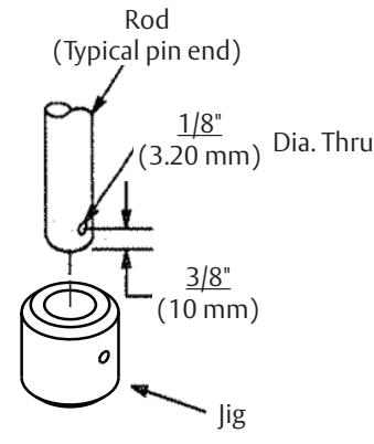
To Cut Rods
- Cut from the end with pin hole. NEVER CUT THREADED END.
- Press Jig until it bottoms over Rod.
- Drill 1/8" (3 mm) dia. hole thru, 3/8" (10 mm) from end of Rod.
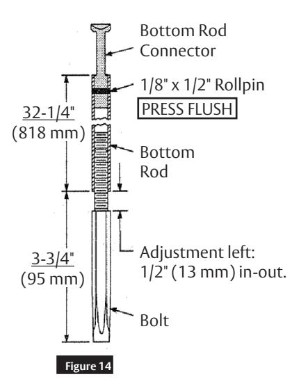
Bottom Rods (Figure 14)
• Ready for 39-15/16" (1014 mm) Floor to device center
To Lower Device
- Bottom Rod cutoff length is distance that device was lowered below 39-15/16" (1014 mm).
- Add to top rod a length equal to the bottom rod cut.
Example:
Device at 36" (914 mm) from floor 39-15/16" - 36" = 3-15/16" (100 mm) The top rod must be lengthened 3-15/16" (100 mm)


FM164 8/22
Exit Devices
Installation Instructions

3 Installation (cont.)
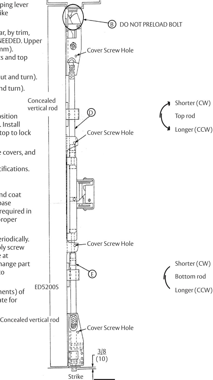
d Complete Installation
- A. Install rods as shown. (Figure 15)
- B. Set strike roller between tripping lever and bolt. Adjust and shim strike as needed.
- C. Test device action by touchbar, by trim, and by dogging. ADJUST AS NEEDED. Upper bolt should retract 1/2" (12 mm). Bolts extend when door shuts and top strike hits tripping lever.
- D. Adjust bottom rod (tilt rod out and turn).
- E. Adjust top rod (tilt rod out and turn).
- F. After acceptable device function, install third screw in top stike to lock stike in position (ED5400) 10-24 x 5/8" FHMS. Install two (2) remaining screws in top to lock strike (ED5470).
- G. Install latch covers, rod guide covers, and device cover. See Figure 1 for fastener specifications.
MAINTENANCE:
- 1. Periodically remove covers and coat mechanisms with a silicone base lubricant. This is particularly required in corrosive environments for proper product function.
- 2. Check mounting fasteners periodically. Retighten if found loose. Apply screw locking compound (available at automotive part stores) or change part fasteners if screws continue to back up.
- 3. Periodic checks (and adjustments) of rods is required to compensate for changes in the opening (e.g. door sagging).
FM164 8/22
Figure 15

4
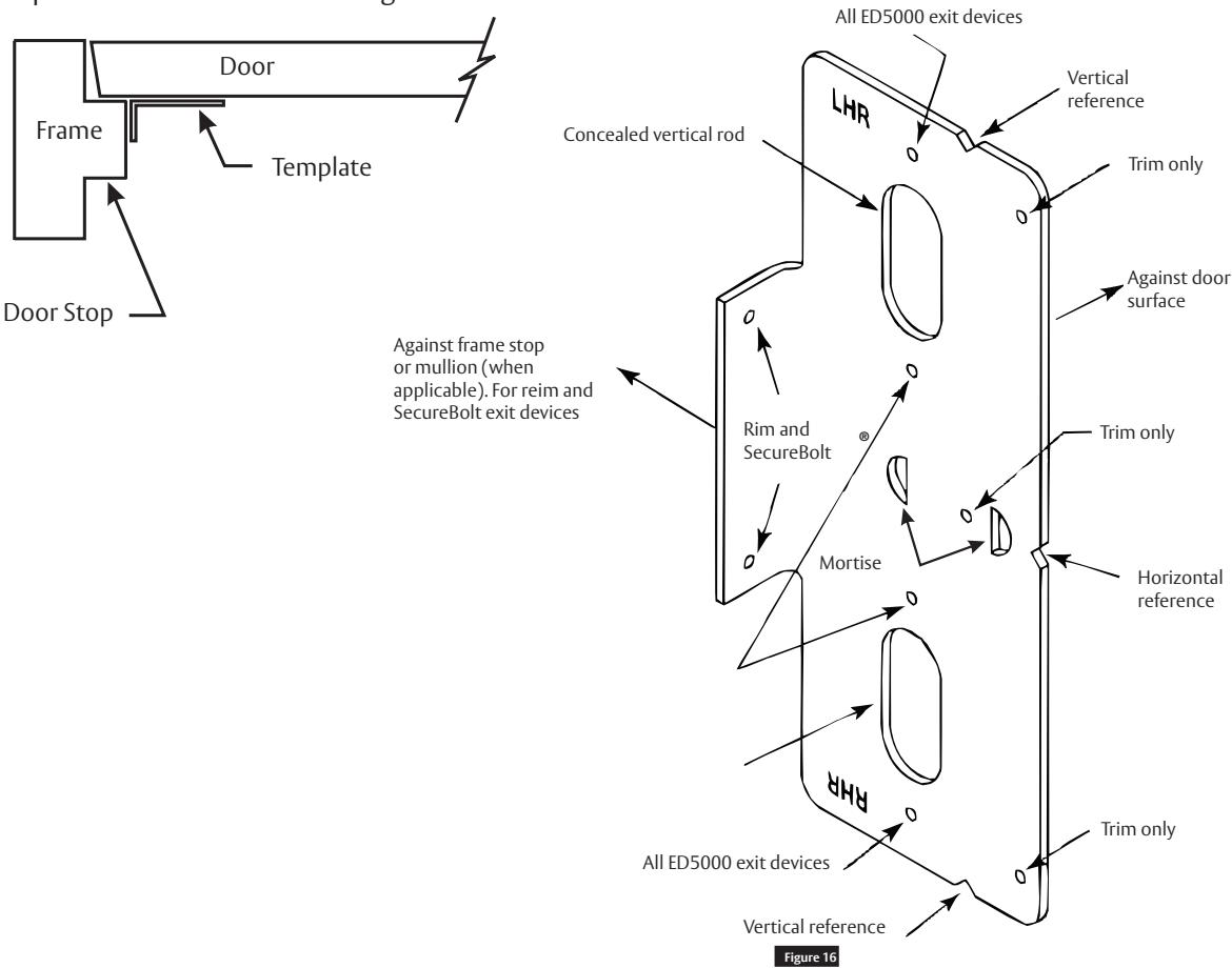
Plastic Installation Template for ED5000 Exit Devices
For use in conjunction with instruction sheets and door marker templates packed with exit device. Holes and slots are identified below by exit device series and trim. Prep door and frame for only those features required for the exit device being installed.
5
Door Templates for ED5000 Exit Devices
ED5400 Top Strike
- 1. For ED5470 series devices omit the ED5400 top strike and use this template with the ED5470 top strike template (page 23).
- 2. Mark to rods line on door face. Note that the centerline of the rods and strikes, used to install top and bottom bolts, is not the vertical reference centerline.
- 3. For LBR devices, omit bottom latch and strike installation steps and see separate instructions for top latch and strike.
- 4. Unreinforced frames require that #10-24 blind rivet nuts (by others) be used to bolt strike. Frames are considered not reinforced when strike mounting screws cannot engage (3) full threads.
- 5. Dimensions are given in inches (mm).
- 6. CAUTION: Office copiers and facsimile machines may change the size of a drawing and make the template inaccurate to use as a door marker.

Installation Instructions

This page intentionally left blank
14 16 " 9 14 " 16 9 22 " 8 7 1 2 FRAME STOP TAPE TO FOLD LINE ( TS OP LINE) #26 (.147" DIA) DRILL 10-24 TAP (2 HOLES) TOP LATCH & STRIKE (ED5400)
BOTTOM BOLT CASE
| CUTLINE | |
4 " 57
CL RODS
33
1 5 16 "
| DOOR/FRAME | FASTENER |
HOLE "A"
PREPARATION |
|---|---|---|
| Metal Reinforced | 1/4-20 PPHMS |
Drill: #7 (.201 dia.)
Tap: 1/4-20 |
|
Thru Bolt
(Metal or Wood) |
1/4-20 SNB |
3/8" (9.5mm) dia.
Thru door |
| Wood Door |
#14 x 1-1/2"
PPH"AB"SMS |
Drill: #9 (.196" dia.) |
TAPE TO
DOOR STOP
ALIGN WITH
( ES E TABLE F I) OR S ZES
A
A
HOLE 'A'

Installation Instructions

This page intentionally left blank
Exit Devices
Installation Instructions

5
Door Templates for ED5000 Exit Devices, continued
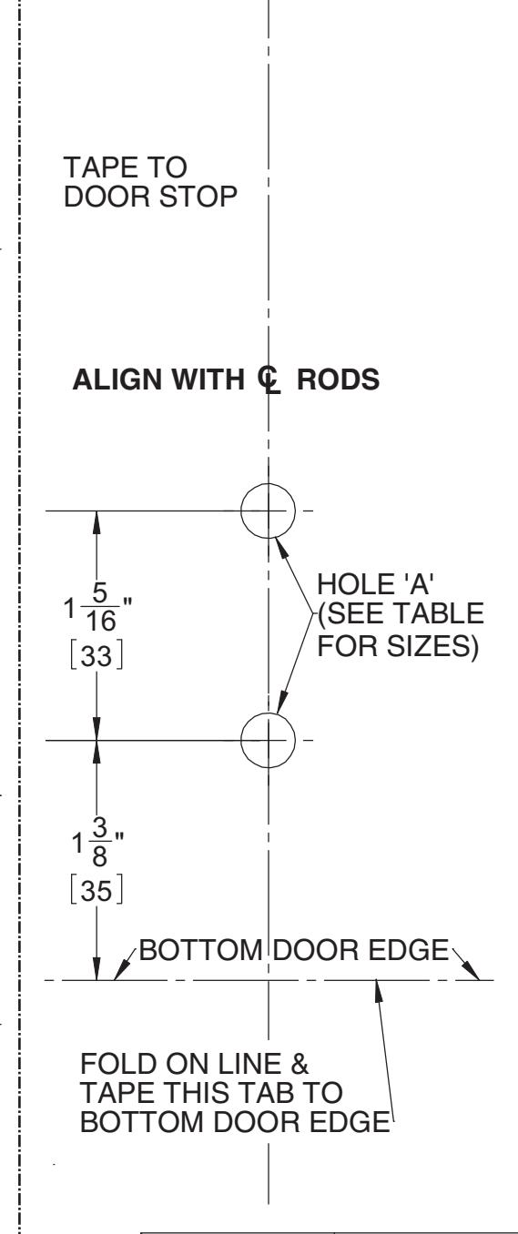
Bottom Strike
- 1. For ED5470 (M55 Option) Less Botton Rod devices omit the bottom strike and use this template with the ED5470 top strike template (page 23).
- 2. Mark L rods line on door face. Note that the centerline of the rods and strikes, used to install top and bottom bolts, so not the vertical reference centerline.
- 3. For LBR devices, omit bottom latch and strike installation steps and see separate instructions for top latch and strike.
- 4. Unreinforced frames require that #10-24 blind rivet nuts (by others) be used to bolt strike. Frames are considered not reinforced when strike mounting screws cannot engage (3) full threads.
- 5. Dimensions are given in inches (mm).
- 6. CAUTION: Office copiers and facsimile machines may change the size of a drawing and make the template inaccurate to use as a door marker.

Installation Instructions

This page intentionally left blank
18

Installation Instructions

This page intentionally left blank

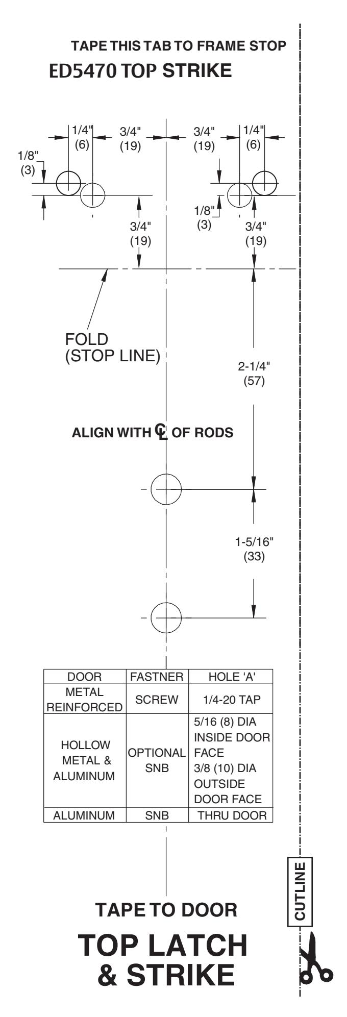
5 Door Templates for ED5000 Exit Devices, continued
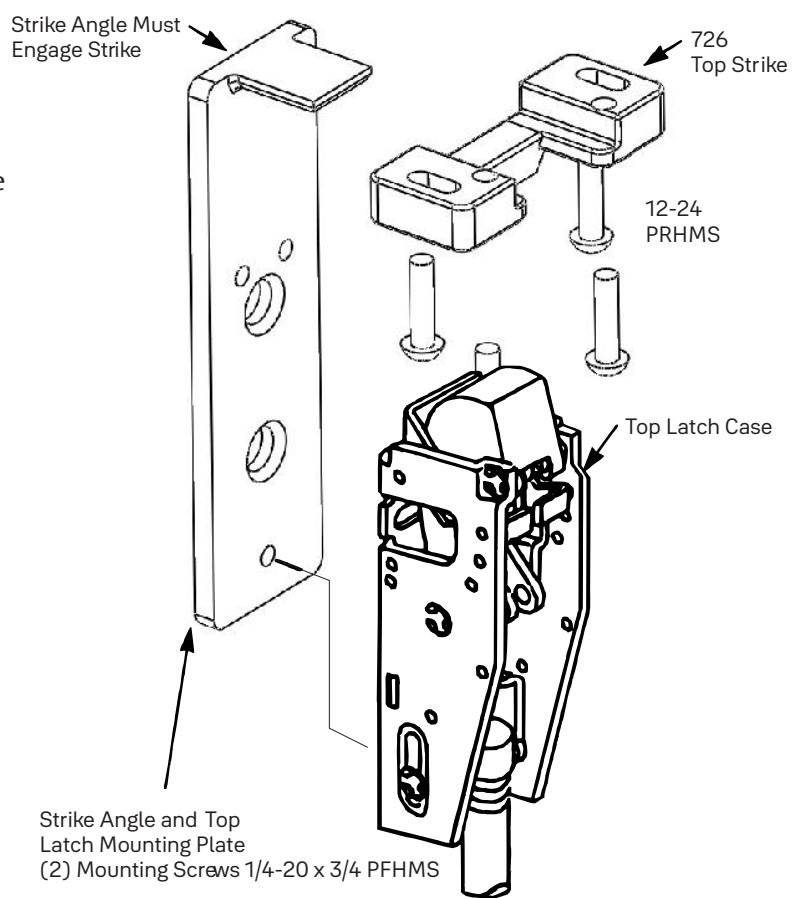
726 Strike
- 1. 726 Strike template used for 7170 series devices.
- 2. Mark rods line on door face. Note that the centerline of the rods and strikes used to install top and bottom bolts, is not the vertical reference centerline.
- 3. For LBR (Less Bottom Rod) devices, omit bottom latch and strike installation and install Top Strike with strike angle and "popper" assembly supplied with device.
Caution: LBR devices should not be used where security is a primary concern.
- 4. Top Strike Installation: With door securely closed, tape template to the door and frame stop. Spot and prepare holes for top strike using (2) 12-24 round head screws, provided. With template still in place, assemble upper mounting plate to the door with the strike angle engaged into the top strike, as shown below. Adjust hole locations for the mounting plate, if required. Spot and prepare (2) outer holes, then prepare (2) inner holes as designed on the template.
- 5. Unreinforce frames require that 12-24 blind rivet nuts (by others) be used to bolt strike. Frames are not considered reinforced when strike mounting screws cannot engage (3) full threads.
- 6. Dimensions are given in inches (mm).
Caution: Office copiers and facsmilie machines may change the size of a drawing and make the template inaccurate to use as a door marker.

Installation Instructions

This page intentionally left blank

Corbin Russwin, Inc. 225 Episcopal Road Berlin, CT 06037 USA Phone: 800-543-3658 Fax: 800-447-6714 www.corbinrusswin.com