Corbin Russwin ED5000 Series ED5200(A), ED5200S(A) Wide Stile Rim, SecureBolt Single Doors or Pairs with Mullion…_FM156
Open the original PDF document
View PDFInstallation Instructions

ED5200(A) ED5200S (A) Series
Rim & Securebolt® Exit Devices
Single Doors or Pairs with Mullion

This product can expose you to lead which is known to the state of California to cause cancer and birth defects or other reproductive harm. For more information go to www.P65warnings.ca.gov.
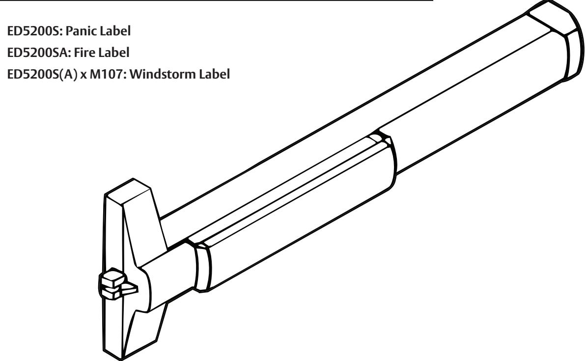
ED5200 (A) & ED5200S(A) Series
Installation Instructions

| TOC | Table of Contents | ||
|---|---|---|---|
| 1 | Package Contents 3 | ||
| 2 | Application and Kit Descriptions 4 | ||
| a |
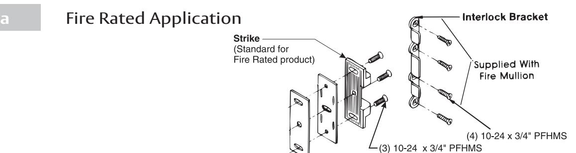
Fire Rated Application
4 |
||
| b | Windstorm Application 4 | ||
| c | Windstorm Shim Kit 4 | ||
| d |
Shim Kit Option (Raised Glass)
4 |
||
| e | Sex Nut Option 4 | ||
| 3 | Check Before Starting 5 | ||
| 4 | Installation 6-10 | ||
| a |
Mark Door
6 |
||
| b | Prepare Door and Frame 6 | ||
| c | Size Device 7 | ||
| d | Clear Raised Door Mounting 7 | ||
| e | Install Device 8 | ||
| f | Install Strike 9 | ||
| g | Install Head Cover and End Cap 10 | ||
| 5 | Maintenance 10 | ||
| 6 | Plastic Template Instructions 11 | ||
| 7 | RHR Door Template 12 | ||
| 8 | LHR Door Template 13 |
Attention Installer
Please read these instructions carefully to prevent missing important steps.
Notes
- Improper installation may result in damage to lock and void factory warranty.
- Other product brand names may be trademarks or registered trademarks of their respective owners and are mentioned for reference only.
ED5200 (A) & ED5200S(A) Series
Installation Instructions

1 Package Contents
Packed for reinforced metal doors, optional sex nuts required for composite, wood, and unreinforced metal doors.
Note
These installation instructions cover only standard products. To install options, use installation instructions packed with optional component, or contact the factory.
| Abbreviation | Fastener Description | ||
|---|---|---|---|
| PPH "AB" SMS | Phillips pan head type "AB" sheet metal screw | ||
| PFHUMS | Phillips flat head under cut machine screw | ||
| PFHMS | Phillips flat head machine screw | ||
| PRH "AB" SMS | Phillips round head type "AB" sheet metal screw | ||
| PTH "AB" SMS | Phillips truss head type "AB" sheet metal screw | ||
| PPHMS | Phillips pan head machine screw | ||
| PFH "AB" SMS | Phillips flat head type "AB" sheet metal screw | ||
For doors of either hand
All dimensions are in inches (mm) unless otherwise noted.
3
ED5200 (A) & ED5200S(A) Series
Installation Instructions

2 Application and Kit Descriptions
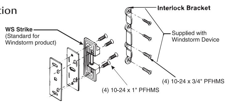
b Windstorm Application

c Windstorm Shim Kit (Option only for 5200S) *
Part Number: 710F468 Black Finish
Kit consists of (3) Latch Head Shims, (3) End Cap Shims, longer fasteners, and longer Spindle Assembly for trim. Each Shim is 1/8 in. (3 mm) thick.
Note
Shim Kit required for Windstorm application.
*Standard with ED5200S(A) x M107 Windstorm Devices

d Shim Kit Option (Raised Glass)
Part Number: 697F338 Black Finish
Kit consists of (2) Latch Head Shims, (2) End Cap Shims, longer fasteners, and longer Spindle Assembly for trim. Each Shim is 1/8 in. (3 mm) thick.
More than two shim thicknesses will require longer device mounting screws.

e Sex Nut Option
Standard for Fire Rated Doors.
Recommended for Unreinforced Metal Doors and Wood Door applications.
| Device | Quantity | Size |
|---|---|---|
| All (Trim) | 6 | 1/4 - 20 |
| All (No trim) | 2 | |
| Fire Mullion (Add) | 4 | 10 - 24 |
ED5200 (A) & ED5200S(A) Series
Installation Instructions

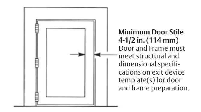
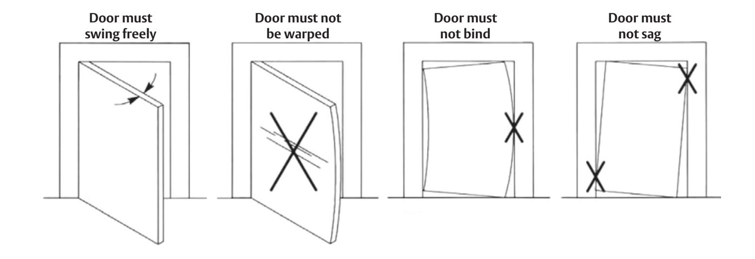
3 Check Before Starting
Unreinforced Door or Frames
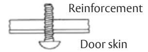
Doors and Frames with walls having a structural thickness (metal skin plus reinforcement, or solid hardwood) to engage less than (3) full screw threads, are considered unreinforced for hardware.
Unreinforced Doors: Use SNB (sex nuts and bolts).
Reinforced Door or Frame engages at least (3) screw threads.
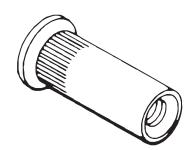
Unreinforced Frames: Use Blind Rivet Nuts.

Note
Recommended fasteners for unreinforced openings are not necessarily supplied by Corbin Russwin, Inc.
ED5200 (A) & ED5200S(A) Series
Installation Instructions

4 Installation
a Mark Doo r
Locate and mark horizontal and vertical reference centerlines, as shown.
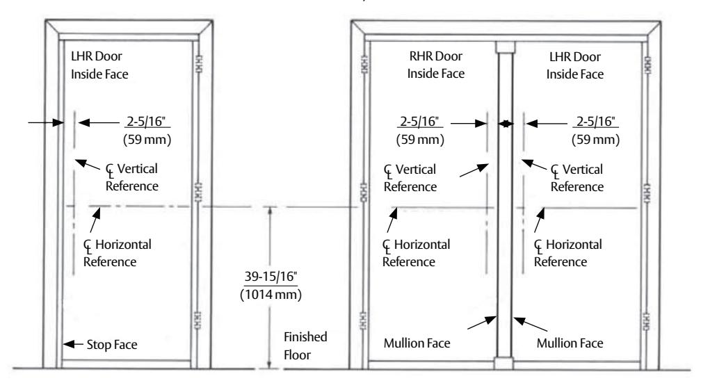
Typical Single Swing Pair with Mullion
b Prepare Door and Frame
- 1. Seat template on door and stop faces.
- 2. Align horizontal and vertical centerlines.
- 3. Locate and tape Trim Template to door. (See instructions packed with Trim)
- 4. Spot and prepare holes. (See caution below).
Device: (2) 1/4"-20 Machine Screws (*), or (2) 3/8" Dia. Sex Nuts & Bolts (10) * Metal reinforced doors only.
Strike: (2) 10-24 Machine Screws, or
(2) #10 Wood Screws
FM156 06/20
ED5200 (A) & ED5200S(A) Series
Installation Instructions

4 Installation (continued)
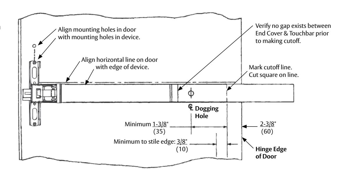
c Size Device
Device must be field cut to size, unless standard opening and device are 36 in. (0.91 m).
LHR Door open 90° inside face
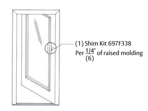
d Clear Raised Door Molding
Device must seat flush on door surface, or on shims that keep it parallel to door face.
One shim Kit 697F338 required for each 1/4 in. (6 mm) of device lift needed. Longer device mounting screws needed when more than (1) shim kits are used.
See "Shim Kits Option" on page 4.
ED5200 (A) & ED5200S(A) Series
Installation Instructions

4 Installation (continued)

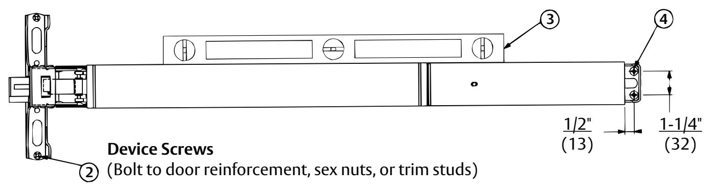
e Install Device
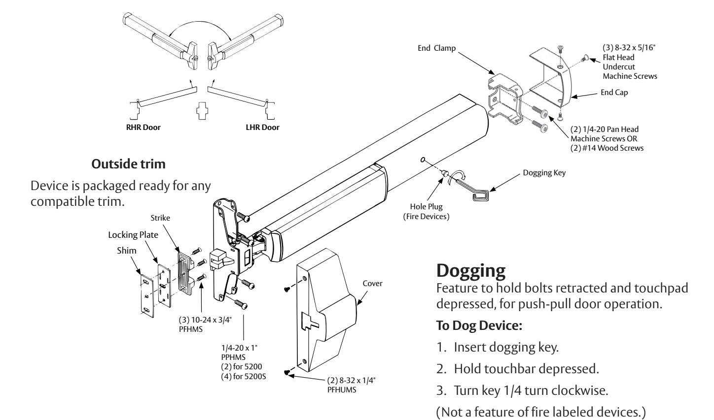
- 1. Mount trim (follow instructions packed with trim).
- 2. Seat bar in place. For ED5200(A), fasten the device head using (2) 1/4-20 x 1" PPHMS or SNB. For ED5200S(A), fasten device head with (4) 1/4-20 x 1" PPHMS or SNB.
- 3. Set bar level. Locate end clamp holes.
- 4. Prepare end clamp mounting holes. Mount end clamp using (2) 1/4-20 x 1" PPHMS or SNB.
-
5. Check bolt retraction.
- A. Depress touchbar (bolt must retract). Release touchbar (bolts must extend).
- B. Actuate trim (bolts must retract). Release trim actuator (bolts must extend).
- C. (NOT FOR FIRE DEVICES). Depress touchbar, turn dogging key clockwise (bar must remain depressed, bolts must remain retracted). Turn dogging key counterclockwise (bar and bolts must return to extended position).
NOTE
When resulting operation is faulty, check first for visible binding or interference. If there is no apparent reason for the fault, remove item from the door and recheck its operation before assuming that it is defective.
6. Tighten all mounting screws.
ED5200 (A) & ED5200S(A) Series
Installation Instructions

4 Installation (continued)
f Install Strike
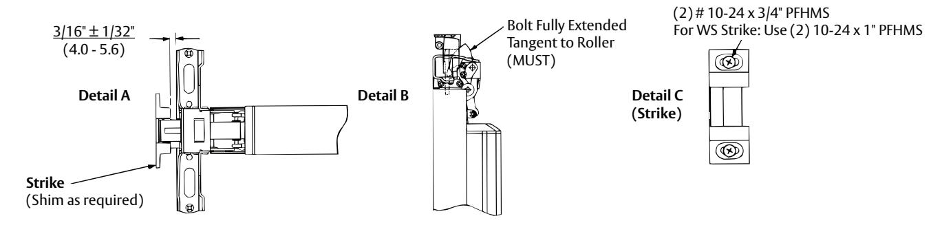
- 1. Position Strike Projection (Strike + Locking Plate + Shims, if needed). See Detail A.
- 2. Position Strike Depth. See Detail B.
- 3. Fasten Strike Securely, as shown on Detail C using (2) 10-24 x 3/4" PFHMS. For WS Strike, use (2) 10-24 x 1" PFHMS.
-
4. Check Bolt Engagement.
- A. Bolt should retract to clear the strike, when actuated by bar, trim, or dogging action. Bolt should consistently re-engage the strike, when actuators are released and the door shuts.
- B. Door should remain latched and not rattle when pushed, pulled, or shaken in/out.
-
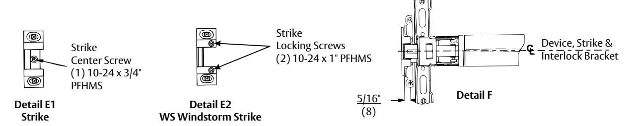
5. Lock strike into place. For regular and Fire application, See Detail E1. For Windstorm application See Detail E2.
- A. Strike Application: Spot and prepare (1) hole using the strike as a template, and install strike center screw (1) 10-24 x 3/4" PFHMS.
- B. Windstorm Strike Application: Spot and prepare (2) holes using the strike as a template, drill through the strike shims and locking plate (when required), then install (2) 10-24 x 1" PFHMS strike locking screws.
-
6. Install Interlock Bracket (Fire Mullion). See Detail F.
- A. Position strike Interlock Bracket in place, as shown. Locate bracket holes.
- B. Prepare Interlock Bracket mounting holes. Mount Interlock Bracket using (4) 10-24 x 1" PFHMS or SNB.
Note
Interlock Bracket and screws supplied with Fire Mullion.
-
7. Install Interlock Bracket (Windstorm Device). See Detail F.
- A. Position strike Interlock Bracket in place, as shown. Locate bracket holes.
- B. Prepare Interlock Bracket mounting holes. Mount Interlock Bracket using (4) 10-24 x 1" PFHMS or SNB.
Note
Interlock Bracket and screws supplied with Windstorm Product supersedes interlock bracket supplied with Fire Mullion (remove and discard when applicable).
FM156 06/20
Rim & SecureBolt® Exit Devices ED5200 (A) & ED5200S(A) Series
Installation Instructions

4 Installation (continued)
g Install Head Cover and End Cap

5 Maintenance
- 1. Periodically remove covers and coat mechanisms with an appropriate lubricant. This is particularly required in corrosive environment for proper product function.
- 2. Check mounting fasteners periodically. Re-tighten if found loose. Apply screw locking compound, or change part fasteners if screws continue to back out.
- 3. Periodic checks and adjustments of strike are required to compensate for changes in the opening (e.g., door sagging, etc...).
ED5200 (A) & ED5200S(A) Series
Installation Instructions

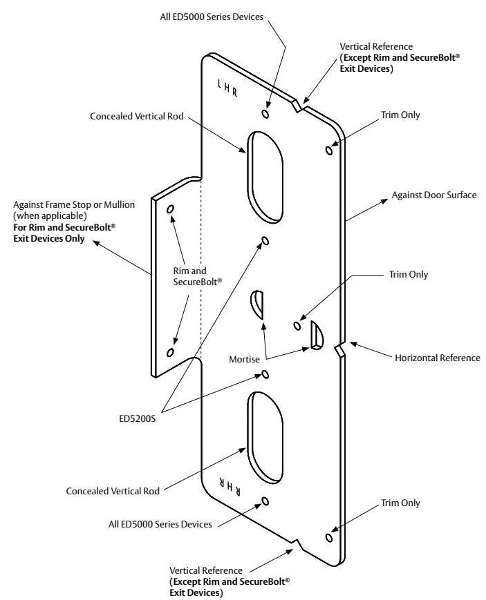
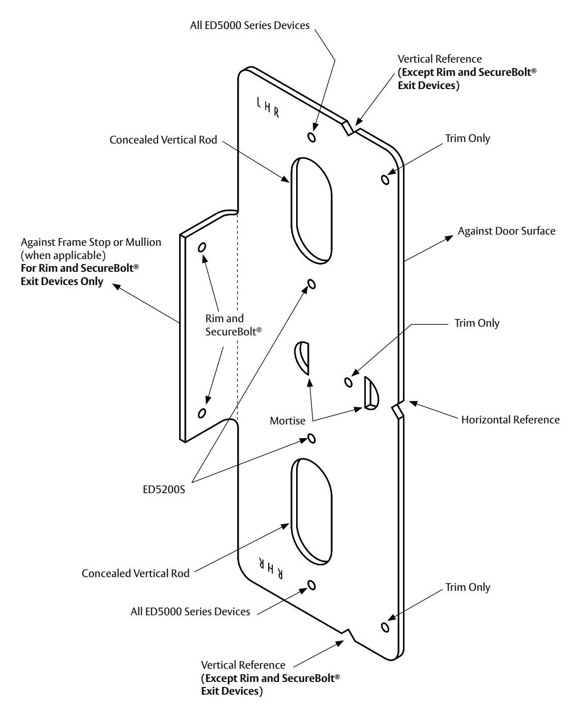
6 Plastic Template Instructions
For use in conjunction with instruction sheets and door marker templates packed with exit device. Holes and slots are identified below by exit device series and trim. Prep door and frame for only those features required for the exit device being installed.
RHR Door
Note: Do not photocopy. Dimensions will not be to scale.
FLIP TO OTHER SIDE FOR LHR DOOR
notocopy. Il not be to scale. Fa Door
Door Inside Face Surface (Device Seat)
REFERENCE
VERTICAL
Drill: #26 (.147" dia.) Tap: 10-24
10-24 Machine Screw
Metal Reinforced
Pilot Hole: 11/64 (4.40mm) dia.
#10 x 1-1/4 " Wood Screw
Solid Hardwood
Β
Drill: #7 (.201" dia.) Tap: 1/4-20
1/4-20 Machine Screw
Metal Reinforced
A and C
PREPARATION
FASTENER
DOOR/FRAME
HOLE
3/8"(9.50mm) dia. thru door
1/4-20 SNB
All others
HORIZONTAL REFERENCE & DEVICE
As required for blind nut used.
See Note 2
All others
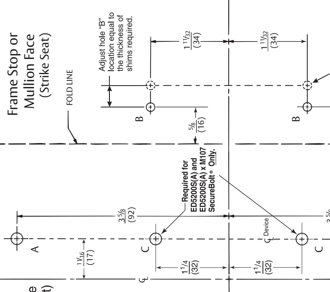
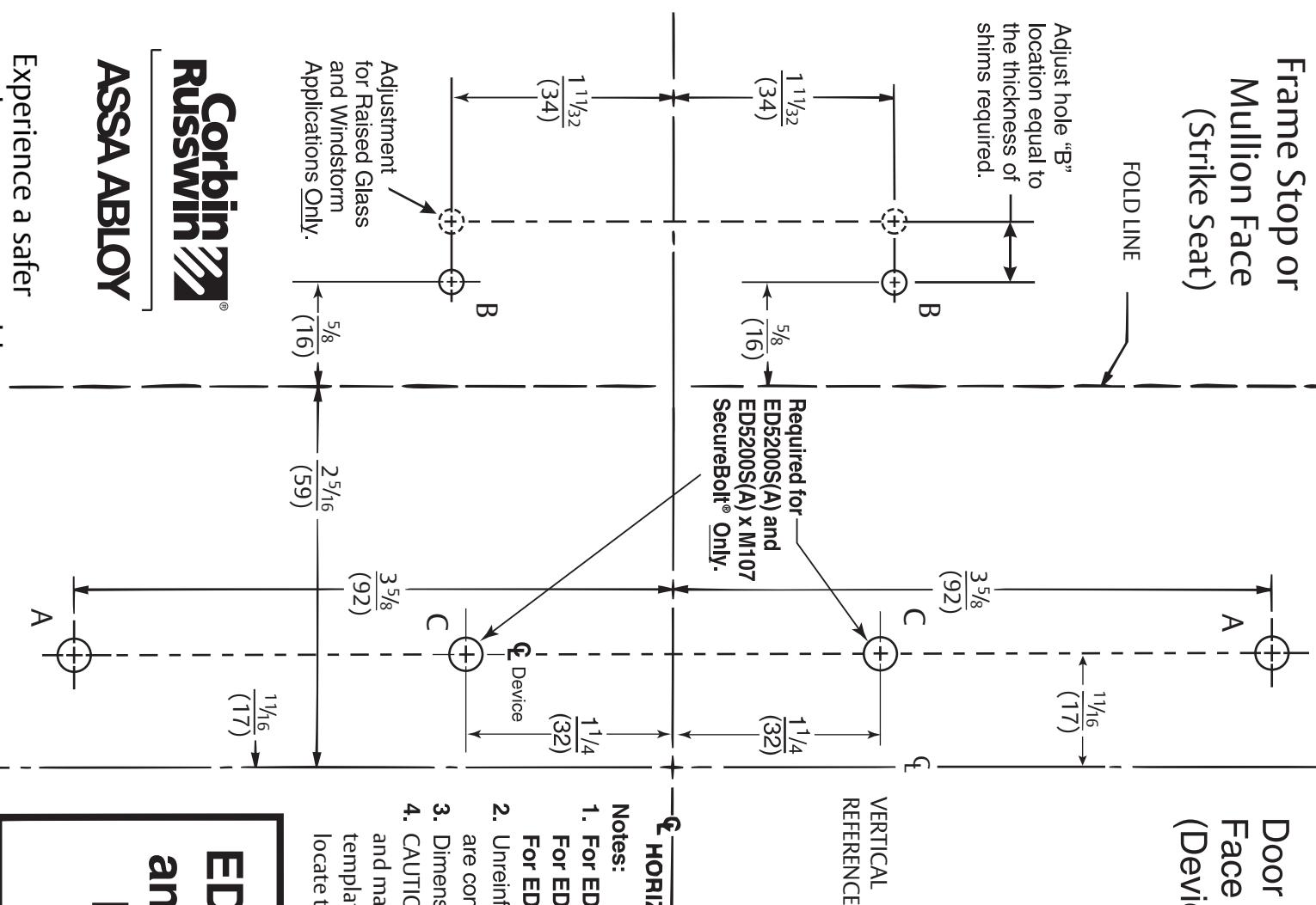
Notes:
1. For ED5200(A): Use with installation instructions FM156 (latest revision)
For ED5200S(A): Use with installation instructions FM532 (latest revision).
Unreinforced Frames require 10-24 blind rivet nuts (by others) be used to bolt strike. Frames are considered not reinforced when strike mounting screws cannot engage (3) full threads. For ED5200S(A) x M107: Use with installation instructions FM532 (latest revision).
- . Dimensions are given in inches (mm).
- . If this is not the original template packed with the trim, use only the dimensions written on the template to CAUTION: Office copiers and facsimile machines my change the size of a drawing ocate the holes on the door (do not use the template as a door marker). and make the template inaccurate to use as a door marker
ED5200(A) Series, ED5200S(A) Series and ED5200S(A) x M107 (Windstorm) Rim and SecureBolt® Exit Devices Door Marker Template
Russwin ASSA ABLOY
for Raised Glass and Windstorm Applications Only.
(16)
5/8
(92)
Adjustment
Experience a safer and more open world
Dimensions will not be to scale. Note: Do not photocopy.
HOLE A and C DOOR/FRAME Metal Reinforced See Note 2 Wood Screw #10 x 1-1/4 Machine Screw 10-24 Machine Screw 1/4-20 All others Solid Hardwood Metal Reinforced All others 1/4-20 SNB Tap: 1/4-20 Drill: #7 (.201 dia.) nut used. As required for blind (4.40mm) dia. Pilot Hole: 11/64 Tap: 10-24 Drill: #26 (.147 dia.) dia. thru door 3/8 (9.50mm) FASTENER PREPARATION
- locate the holes on the door (do not use the template as a door marker). template packed with the trim, use only the dimensions written on the template to and make the template inaccurate to use as a door marker. If this is not the original CAUTION: Office copiers and facsimile machines my change the size of a drawing
Rim & SecureBolt® Exit Devices ED5200 (A) & ED5200S(A) Series
Installation Instructions

Rim & SecureBolt® Exit Devices ED5200 (A) & ED5200S(A) Series
Installation Instructions


Corbin Russwin, Inc. 225 Episcopal Road Berlin, CT 06037 USA Phone: 800-543-3558 Fax: 800-447-6714 www.corbinrusswin.com
ASSA ABLOY is the global leader in door opening solutions, dedicated to satisfying end-users needs for security, safety, and convenience