Corbin Russwin ED5000 Series 955 959 Trim Installation Instructions
Open the original PDF document
View PDFInstallation Instructions
- 1. Assemble trim. See previous page for components and instructions.
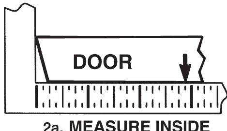
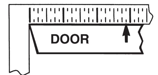
- 2. After marking door inside face for device location (Device Instructions), transfer "Vertical Reference Centerline" from inside to outside door face. Follow steps 2a. and 2b. below.

- 3. Transfer "Horizontal Reference Centerline" from inside to outside door face.
- 4. Align trim template and tape to outside door face. CAUTION: Office copiers and facsimile machines may change the size of a drawing and make the template inaccurate to use as a door marker. If this is not the original template packed with the trim, use only the dimensions written on the template to locate the holes on the door (do not use the template as a door marker).
- 5. Spot holes and prepare door for trim.
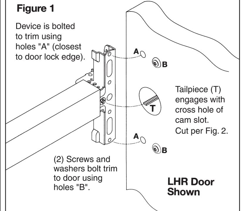
- 6. Mount trim to door thru holes "B". Fasten, finger tight only, with 2 screws and washers seating on door, as shown in Figure 1.
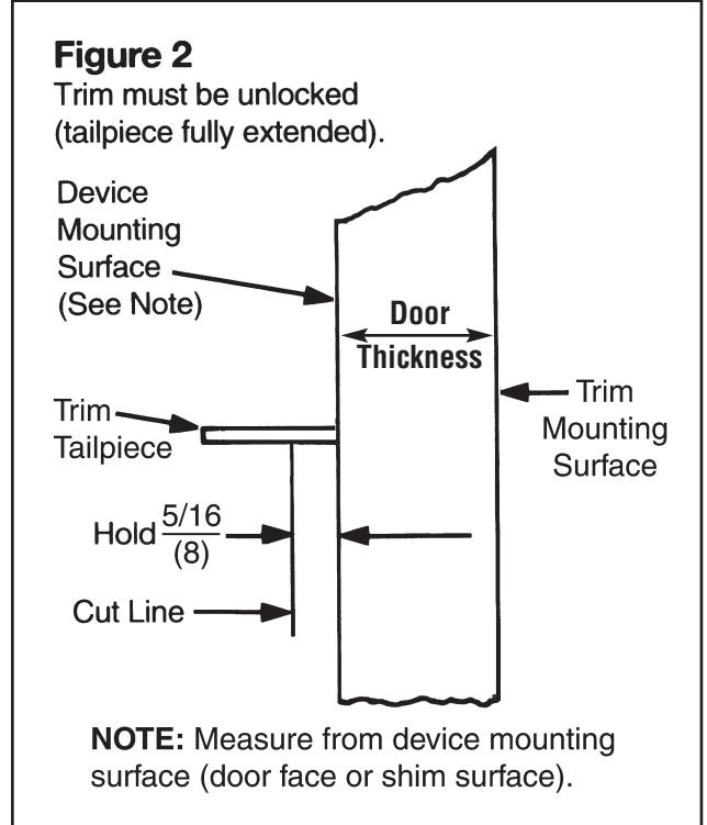
- 7. With trim unlocked (tailpiece turning when lever is rotated), cut trim tailpiece as shown in Figure 2.
- 8. Seat device so that trim tailpiece penetrates cam slot, as shown in Figure 1. Continue as shown in device instructions.

Installation Instructions
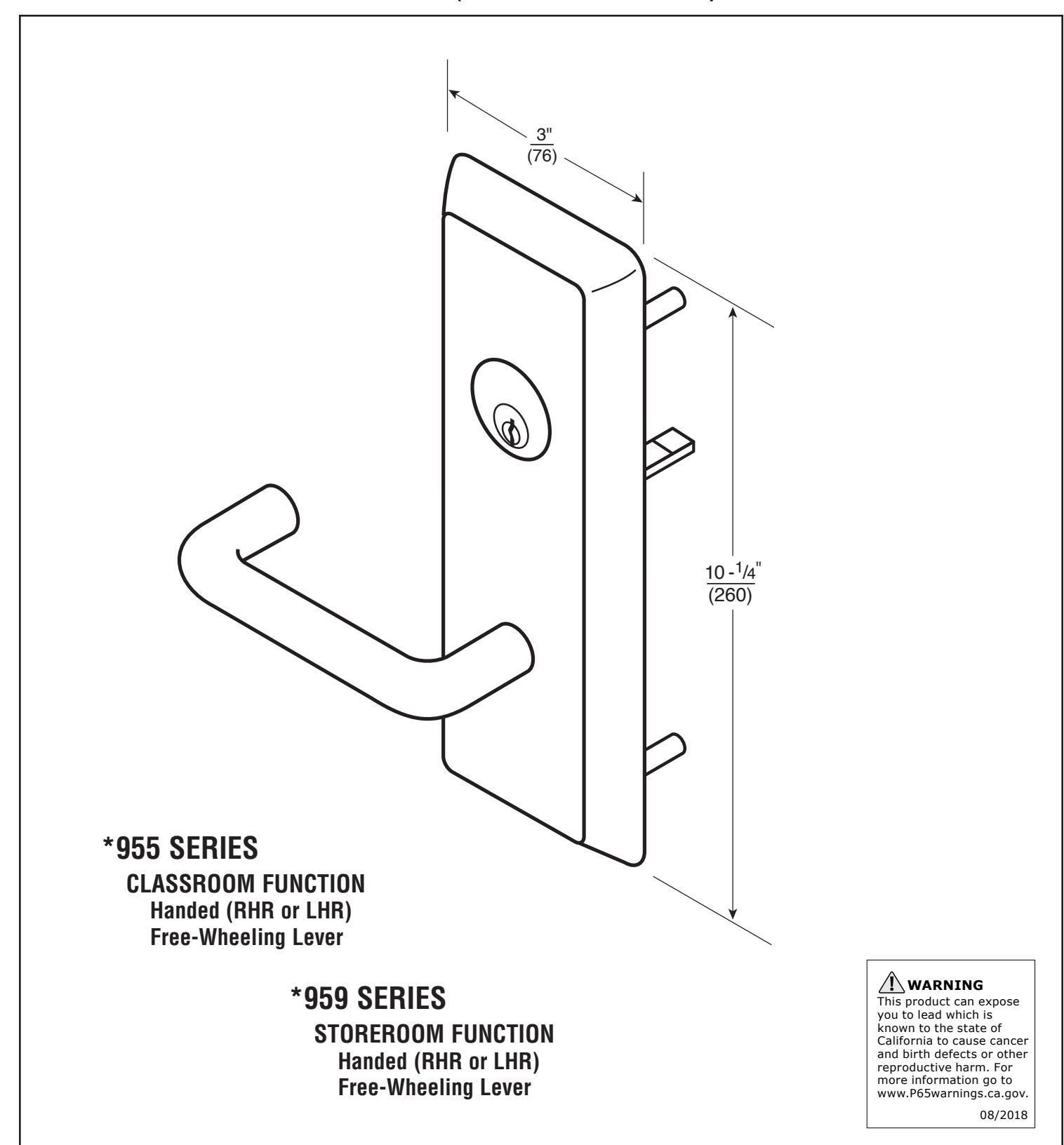
*955 and *959 SERIES HEAVY DUTY TRIM
For use with ED5000 Series Exit Device (Wood and Metal Doors)
FM 193 10/18
* Represents prefix letter(s) for various lever designs.
Trim Template Outside Door VERTICAL Face REFERENCE ( Trim) HOLES MARKED "X" (17)(4 Places) METAL DOORS: Inside Face 5/16" (8) Dia. Outside Face 1/2" (13) Dia. Radius WOOD DOORS: 1/2" (13) Dia.Thru 1-1/4 Deep Slot Dimensions given in <u>Inches</u> (32) Shaded Area (92) 2-7/8 (73) Radius HORIZONTAL REFERENCE (Device and Trim) (51)\<u>1/2</u> Dia. Thru 3-5/8 (92)Corbin 77 Russwin 77 See Chart ASSA ABLOY Radius 4 "X" HOLES In U.S.: Corbin Russwin, Inc. 225 Episcopal Road Berlin, CT 06037 USA Phone: 800-543-3658 Technical Product Support: Phone: 888-607-5703 ASSA ABLOY Door Security Solutions Canada 160 Four Valley Drive Vaughan, Ontario, Canada L4K 4T9 Phone: 800-461-3007 ASSA ABLOY, the global leader in door opening solutions
Trim Assembly Instructions
Corbin Russwin ASSA ABLOY
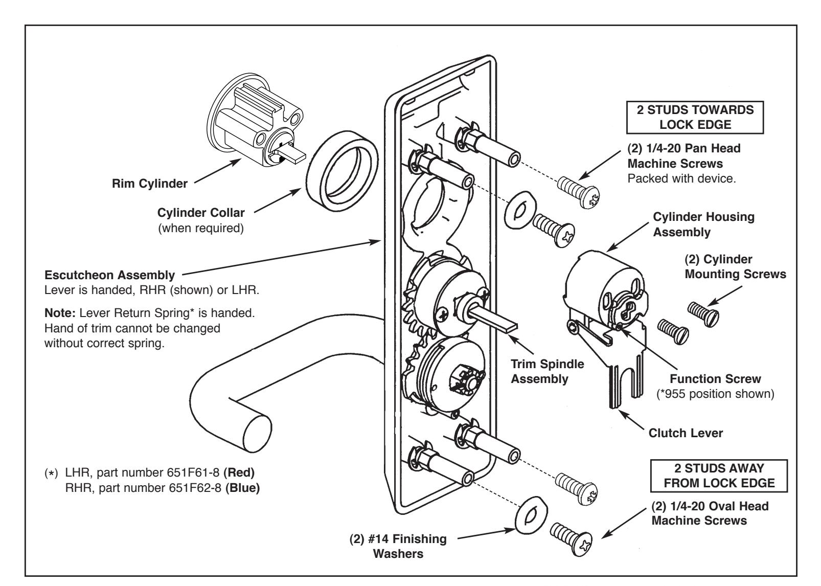
1. Check cylinder components.
NOTE: Cylinders longer than 1-1/8" (29) will require collars. Refer to Corbin Russwin cylinder collar chart.
2. When required, cut cylinder tailpiece.
Correct length is 1/16" to 3/16" (2 to 5) beyond cylinder housing cam.
3. Assemble cylinder.
Insert cylinder housing prongs into matching notches of escutcheon. Pass cylinder tailpiece thru cylinder collar (when required) and slot in cylinder housing cam. Fasten cylinder using (2) mounting screws. DO NOT OVERTIGHTEN SCREWS.
4. Check cylinder action.
Rotate cylinder tailpiece to cam the clutch lever down. This depresses the trim spindle assembly which disengages the trim spindle from the lever handle, putting the trim in a free-wheeling, locked mode.
5. Determine trim function.
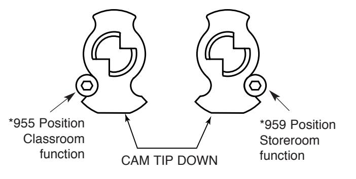
*955 (Classroom) – Key locks/unlock lever handle *959 (Storeroom) – Key locks/unlocks lever handle
Key removable ONLY in locked position.
6. To change trim function:
Rotate cam tip to down position (locked mode). Move function screw as shown.
|
Corbin Russwin
Cylinder Collar Chart |
|
|---|---|
| Cylinder Length | Collar |
| 1-1/8" (29) | None |
| 1-1/4" (32) | 654F07 ** |
| 1-1/2" (38) | 654F08 ** |
** Specify finish