Corbin Russwin ED40AK and ED50AK Alarm Retrofit Kit for ED4000 and ED5000 Series Narrow and Wide Stile M61 Optio…_FM542
Open the original PDF document
View PDF

Installation Instructions
ED4000 & ED5000 SERIES EXIT DEVICES with M61 ALARM OPTION and ED40AK & ED50AK ALARM RETROFIT KIT
FM 542 11/18
ED4000 & ED5000 Series Exit Devices x M61 Alarm Option
Available for all exit device types
ED40AK & ED50AK Alarm Retrofit Kit
Available for field retrofit of all devices except Surface Vertical Rod
EXIT ALARM INSTRUCTIONS
STEP 1 – Install Touchbar Switch Retrofit Applications Only - All Except SVR
- 1) Remove Device from door.
- 2) Remove End Cover and black End Plate. Discard End Plate.
- If Device has dogging, remove dogging assembly with (2) screws and discard.
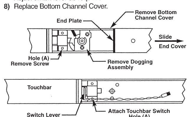
- 4) Remove Bottom Channel Cover from Device.
- Locate rear touchbar mounting hole (A) as indicated below. Remove screw, if one is assembled, and install in opposite hole.
- 6) Remove screw from Touchbar Switch Bracket and align screw hole over touchbar mounting hole (A). Reinstall screw from bottom of channel to secure Switch Bracket.
- Verify that moving the Touchbar causes the switch to trip. Adjust switch lever as required.
STEP 3 - Assemble Alarm End Cover
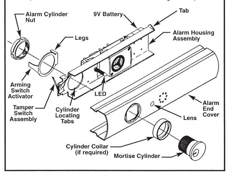
- 1) Slide Alarm Housing Assembly into Alarm End Cover, making sure tabs are engaged and LED is inserted into lens.
-
Insert Cylinder, with Collar if required, into Alarm End Cover aligning cylinder grooves with locating tabs on housing assembly.
- Note: Cylinder keyway to be positioned towards Touchbar.
- 3) Install Arming Switch Activator over Cylinder so that Activator legs are on each side of toggle switch.
- 4) Secure parts with Alarm Cylinder Nut, making sure Activator rotates freely. Check that rotating the key causes Activator to trip switch in both directions. Bend Activator legs as required.
STEP 2 - Size End Cover
- For NEW installations, follow procedures in Device installation instructions.
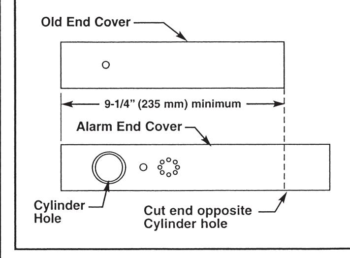
- For RETROFIT applications, cut new Alarm End Cover to same length as old End Cover.
- Cut Alarm End Cover on end opposite Cylinder hole as shown.
Note: Cover can be cut to a minimum length of 9-1/4" (235 mm), not including thickness of End Plate.
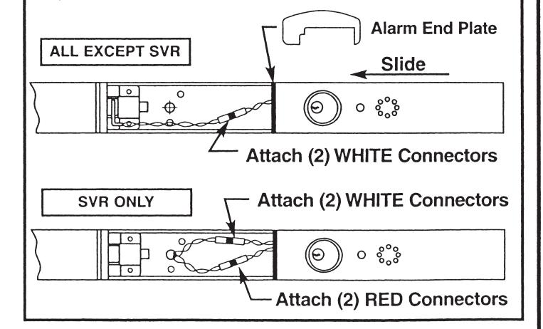
STEP 4 - Install Alarm Assembly
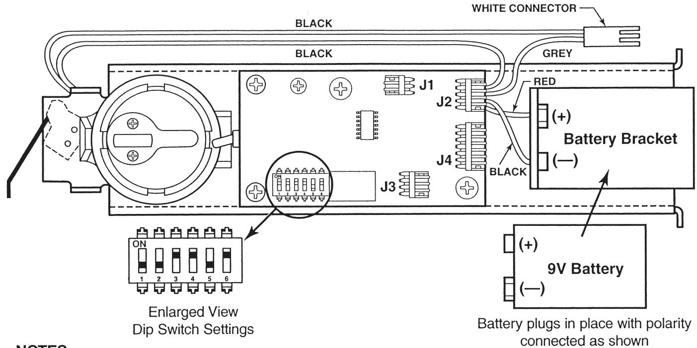
- 1) Install 9V Battery with correct polarity. Verify all connections and switch settings. (See Tables 1, 2 and 3 on next page).
- 2a) ALL EXCEPT SVR Attach (2) white connectors.
-
2b) SVR FACTORY-WIRED ONLY
- Attach (2) white connectors and (2) red connectors.
- Install Alarm End Plate while sliding Alarm End Cover onto Device. Make sure wires are not pinched or cut.
- 4) Install Device on door and check alarm functions.
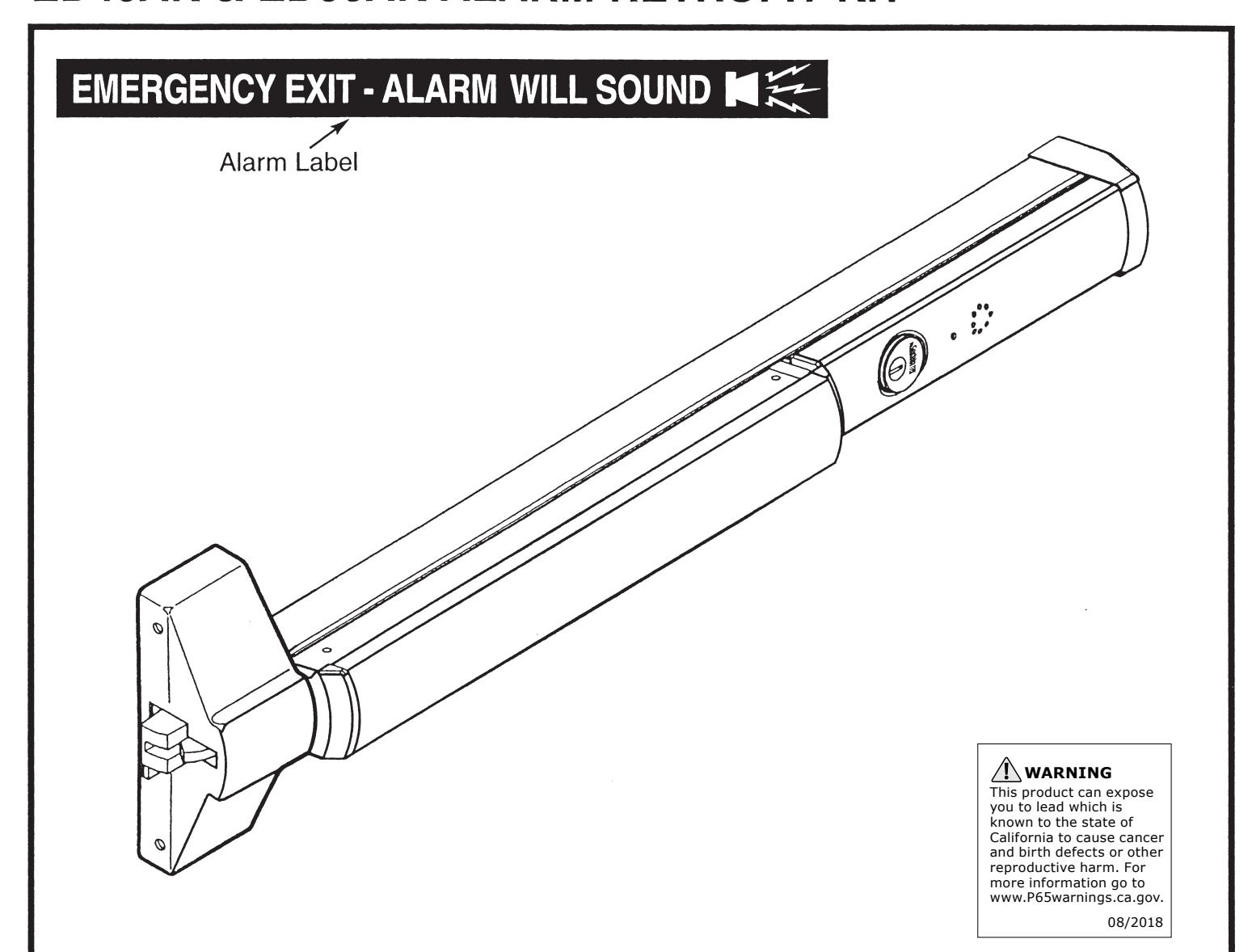
- 5) Install Alarm Label on Touchbar or on door above device.

ALARM FUNCTION AS SHIPPED
- 1) Upon arming, LED will flash AMBER and device will allow egress without triggering alarm for 7 seconds. Time Delay is factory preset see Table 1.
- 2) After 7 seconds, alarm will chirp one time and device will be ARMED . The LED will flash RED every 30 seconds, indicating device is ARMED .
- 3) Once device is ARMED, egress will result in an alarm sound that will stop only when device is RE-ARMED by key.
- 4) Low Battery Indicator Alarm will chirp every 10 seconds, indicating battery needs to be replaced.
NOTES:
- Alarm PC Board has Dip Switches DS-1, 2, 3, 4, and 5 factory preset per Tables 1, 2, and 3 shown below.
- Dip Switch DS-6 is for "hard wire" configurations and setting does not affect stand-alone battery operation.
| Passage Time Delay When the device is initially ARMED by key, the LED will flash AMBER and allow egress for a time defined\nin Table 1. | TABLE 1 | ||
|---|---|---|---|
| DS-1 | DS-2 | Time Delay | |
| *Off | *Off | 7 Seconds | |
| Off | On | 10 Seconds | |
| On | Off | 15 Seconds | |
| On | On | 20 Seconds | |
| Automatic Alarm Reset | TABLE 2 | ||
| The alarm can be set so that it will reset itself after a violation has occurred per Table 2. If the device automatically resets, the indicator light will flash GREEN every 30 seconds instead of RED to indicate a violation has occurred. | DS-3 | DS-4 | Reset Time |
| Off | Off | 2 Minutes | |
| Off | On | 5 Minutes | |
| On | Off | 10 Minutes | |
| *On | *On | No Auto Reset | |
| Armed and Violation LED Color Selection | TABLE 3 | ||
| Device is shipped standard, per Table 3, so that RED LED flashes every 30 seconds when device is ARMED , and flashes GREEN every 30 seconds under auto reset, when door has been violated. | DS-5 |
Armed
LED Color |
Armed Violation
LED Color |
| *Off | Red | Green | |
| On | Green | Red | |
* Factory Preset
|
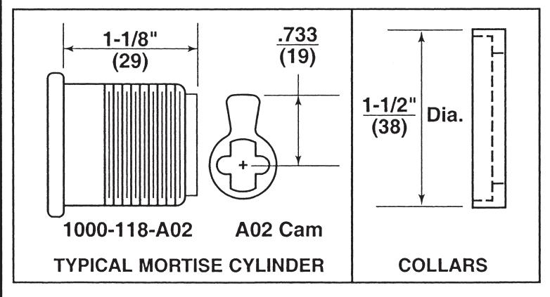
CYLINDER
LENGTH |
1-1/8" (29) | 1-1/4" (32) | 1-1/2" (38) |
|---|---|---|---|
| COLLAR | NONE | 270F15 | 654F07 |

In U.S.: Corbin Russwin, Inc. 225 Episcopal Road Berlin, CT 06037 USA Phone: 800-543-3658
Technical Product Support: Phone: 888-607-5703
In Canada: ASSA ABLOY Door Security Solutions Canada 160 Four Valley Drive Vaughan, Ontario, Canada L4K 4T9 Phone: 800-461-3007