Corbin Russwin ED4000 and ED5000 Series Monitors Installation Instructions
Open the original PDF document
View PDFExit Devices with: Electric Latch Pullback (M94 Option) and/or Monitors (M91, M92, M93 Options)

FM493B 3/10 (617416048)
a. INSTALL SYSTEM PERIPHERAL COMPONENTS (781N Electric Latch Pullback Controller, Controlling Switches, Power Transfer Hinge(s), etc.) AND RACEWAYS:
| WIRES FROM POWER SUPPLY TO DEVICE (Minimum Gauge of Two-Conductor Cable) | |
|---|---|
| Up to 40 Feet of Wire | 16 Gauge |
| Up to 60 Feet of Wire | 14 Gauge |
| Up to 100 Feet of Wire | 12 Gauge |
INTEGRAL POWER SUPPLY - Connect Wires from Power Transfer Hinge, Controlling Switch(es)/ Console and Power (120 VAC) Input to 781N ELECTRIC LATCH PULLBACK CONTROLLER. Refer to Installation Instructions for 781N ELECTRIC LATCH PULLBACK CONTROLLER, packed with 781N Controller Unit.
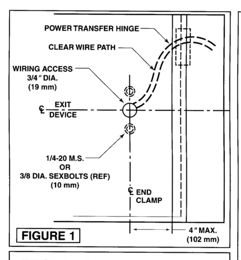
POWER TRANSFER HINGE - Follow Manufacturer's installation instructions. DOOR LEAF WIRES MUST EXIT THROUGH DOOR ACCESS HOLE UNDERNEATH DEVICE END CLAMP.
b. INSTALL DEVICE (and TRIM, if used):
Follow the installation instructions for Device (and Trim). Install the Device less End Clamp and End Cap. Set bar level and prepare End Clamp mounting holes.
c. PREPARE WIRING ACCESS HOLE:
Drill a 3/4" (19mm) diameter hole on centerline of Device and in line with End Clamp mounting holes. See Figure 1 on reverse side. Mount End Clamp.
d. CHECK DEVICE ACTION:
Actuate Device by Touchbar (and by Trim). Door and Device should operate properly. Door should open freely and close securely.
e. CONNECT DEVICE "LATCH PULLBACK" WIRES (if used):
Red & Black polarized wires from inactive (hinge) end of Device connect to designated terminals in the 781N Controller. Refer to wiring diagram on 781N Controller.
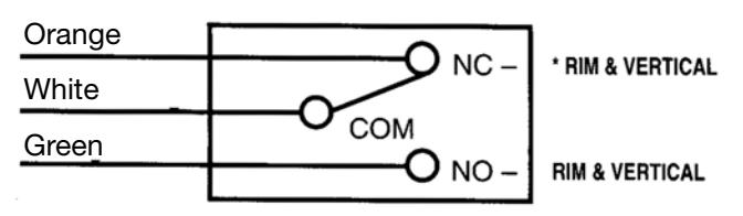
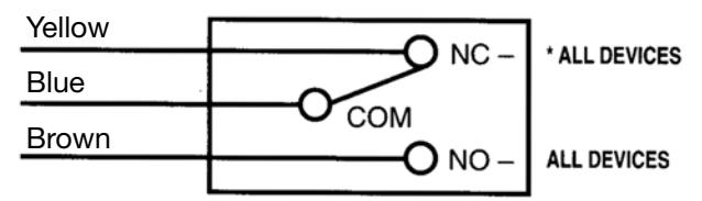
f. CONNECT MONITORS (if used):
See "MONITORS" section on reverse side. Connect as shown. Wire nuts not supplied.
g. TWO DEVICE ZONES:
When two (2) Devices are hooked to the same 781N Controller, repeat steps b. through f. for each Device.
h. TEST SYSTEM:
WITH POWER DISCONNECTED VERIFY THROUGHOUT THAT THERE ARE NO SHORT CIRCUITS. APPLY POWER TO CONSOLE (if used), THEN TO INTEGRAL POWER SUPPLY. Test Device: bolt should retract when controlling switch closes contacts, extend when switch contacts open. Momentary or continued operation, Device status will correspond to switch contact status. WHEN NEEDED, FOLLOW TROUBLESHOOTING GUIDE ON REVERSE SIDE.
TROUBLESHOOTING GUIDE
a) Identify problem.
b) Follow numbered solutions, in sequence given.
| PROBLEM | SOLUTION |
|---|---|
|
1,2,3,6,8 |
|
2,4,5,6,7,8,9 |
| Sluggish bolt retraction. | 2,4,5,6,7,9 |
|
2,6,8 |
|
1,2,5,7,8 |
| • Bolt(s) not retracting in full. | 5,7,9 |
|
1,4,5,6,8,9 |
SOLUTIONS
- CHECK REMOTE SWITCH(ES)
- 2. CHECK CIRCUIT CONTINUITY.
- 3. CHECK FUSES.
- 4. CHECK DOOR (MUST SWING FREELY).
- CHECK MANUAL DEVICE ACTION (MUST WORK PROPERLY).
- CHECK WIRING (CONNECTIONS AND INSULATION).
- CHECK FOR FOREIGN MATERIALS (DEVICE SHOULD BE FREE FROM OBSTRUCTIONS).
- 8. CHECK CIRCUIT BOARD OPERATION.
- CHECK WIRES TO DEVICE (GAUGE VS. LENGTH).
MONITORS (M91, M92, and M93 Options)
CONNECT AS SHOWN BELOW TO DEVICE SPECI-FIED ON SYSTEM SCHEMATIC. Discard unused lead (seal end with wire nut).
"M91" BOLT MONITOR
Slider actuated SPDT switch to indicate bolt(s) extended-retracted.
"M92" TOUCHBAR MONITOR
Touchbar actuated SPDT switch to indicate egress in progress.
"M93" TRIM MONITOR
Device actuated SPDT switch to indicate door open from outside.
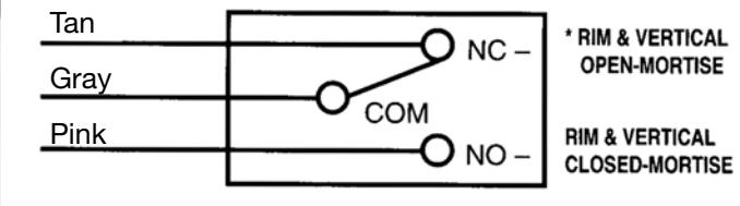
*SWITCH POSITION WITH DOOR SECURE AND DEVICE LATCH ENGAGED.

ASSA ABLOY
In U.S.:
Corbin Russwin, Inc. 225 Episcopal Road Berlin, CT 06037 USA Phone: 860-225-7411
In Canada:
ASSA ABLOY Door Security Solutions Canada 160 Four Valley Drive Vaughan, Ontario, Canada L4K 4T9 Phone: 800-461-3007
FM493B 3/10 (617416048)
Copyright © 1998, 2010 Corbin Russwin, Inc., an ASSA ABLOY Group company. All rights reserved. Reproduction in whole or in part without the express written permission of Corbin Russwin, Inc. is prohibited.