Corbin Russwin DL2200 and DL3200 Series Deadbolt Locks Installation Instructions_FM331
Open the original PDF document
View PDFInstallation Instructions DL2200 & DL3200 Series
In U.S.: Corbin Russwin, Inc. 225 Episcopal Road Berlin, CT 06037 USA
Berlin, CT 06037 USA Vaughan, Ontario, Canada L4K4T9 www.corbinrusswin.com www.assaabloy.ca Technical Product Support: Phone: 888-607-5703
160 Four Valley Drive
ASSA ABLOY Door Security Solutions Canada

ASSA ABLOY
WOOD DOOR PREPARATION
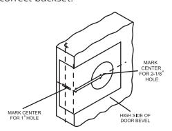
MARK HOLES
Using enclosed template, mark door as illustrated at desired lock height and correct backset.
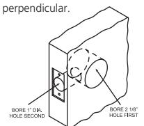
BORE TWO HOLES
Drill 2-1/8" hole through both sides of the door as shown and 1" dia. hole into front face of the door. Be certain holes are
FRAME PREPARATION MORTISE FRAME FOR STRIKE
Even if strike box is not used, recess in jamb mus be deep enough to allow bolt to extend its full length.
3
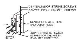
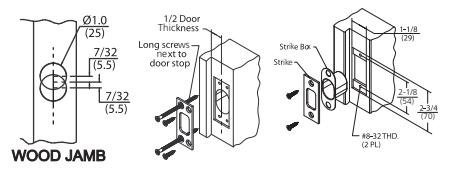
INSTALL STRIKE ON WOOD JAMB
Mark jamb exactly opposite centerline of latch hole. Bore two 1" dia. holes 7/32" above and below height line to depth of 1-18 Mortise for strike and box strike. Install and fasten four screws as illustrated. NOTE: Drill 1/8" dia. pilot holes for 3/4" long screws.
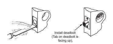
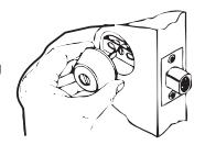
1 INSTALL DEADBOLT
Insert deadbolt in hole, keeping it parallel to face of the door and scribe line around face plate. Remove deadbolt and chisel out scribed area to depth of 5/32" or until face is fulsh with door edge insert deadbolt and fasten with two screws.
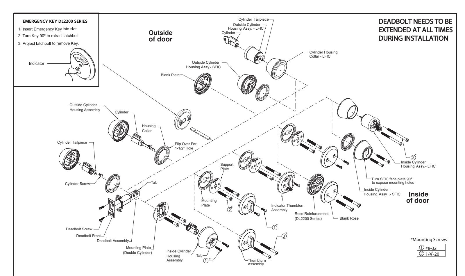
INSTALL OUTSIDE TRIM
Extend deadbolt. Install cylinder housing without key keeping cylinder tailpiece in line with cam slot.
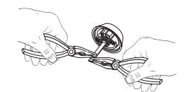
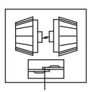
TAILPIECE MODIFICATION
THICK DOOR
Measure door thickness. If the tailpiece needs to be shortened; grip the tailpiece with plie on both sides of the score mark and twist to break off tailpiece excess.
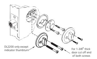
ATTACH INSIDE TRIM
Position mounting plate on door inside of the hole. Insert and tighten two 1/4"-20 machine screws. Place turn piece assembly onto tailpiece and align screw holes fasten with two turn piece screws.

NOTE: Do not use a power driver to tighten Housing Screws, only use hand tool for tightening and adjustment
A WARNING
This product can expose you to lead which is know to the state of California to cause cancer and birth defects or other reproductive harm. For more information go to www.p65warnings.ca.gov.
Experience a safer and more open world
Installation Instructions DL2200 & DL3200 Series
In U.S .: Corbin Russwin, Inc. 225 Episcopal Road Berlin, CT 06037 USA www.corbinrusswin.com
In Canada: ASSA ABLOY Door Security Solutions Canada 160 Four Valley Drive Vaughan, Ontario, Canada L4K4T9 www.assaabloy.ca
ASSA ABLOY
4
DOUBLE CYLINDER-OUTSIDE
Place the outside cylinder housing (with key removed from cylinder) on door with cylinder tailpiece going through cam slot of deadbolt and mounting holes align with holes on deadbolt.
For Fixed Core (FC) cylinder. fasten the outside housing to door with two (2) 1/4-20 mounting screws and mounting plate.

DOUBLE CYLINDER-INSIDE
Place the inside FC cylinder or inside Interchangeable Core housing assembly onto assembly with tailpiece going through cam slot of deadbolt /flat side of tailpieces meet within slot)
For FC cylinder, place the inside cylinder housing assembly over For PC cylinder, place the inside cylinder housing assembly or the cylinder, making certain that tab on housing is engaged in keyway slot on cylinder plug. Insert key and turn until screw holes are exposed, use two (2)
#8-32 screws to fasten the inside cylinder housing to the assembly
For LFIC cylinder, use two (2) 1/4-20 screws to fasten the inside cylinder housing to the assembly.
FLAT SIDES MEET
Technical Product Support: Phone: 888-607-5703

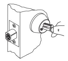
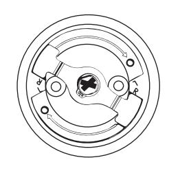
SMALL FORMAT INTERCHANGEARIE CORE
Verify the cam is in the correct position before installing the core. If not, rotate cam to correct position, then insta
5A
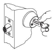
DOUBLE CYLINDER-INSIDE
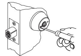
Remove cylinder by inserting control key, turn 15° to right and pull on key. Using cylinder, as shown, rotate face plate to the left to expose head of mounting screw.

Tighten it using #2 Phillips screwdriver.

Using core, rotate face plate to the right and tighten second screw.

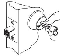
Rotate face plate to position to accept core. Insert interchangeable core into inside cylindernhousing, turn control key to the left (this locks interchangeable core into assembly and remove key.
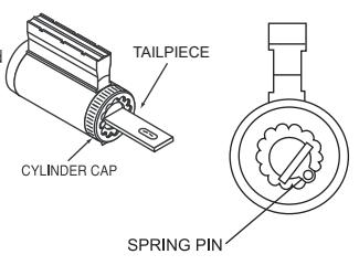
HOW TO CHANGE TAILPIECE
Depress spring pin and unscrew cylinder cap. Remove and replace tailpiece. Screw cylinder cap on to plug while holding spring pin depressed until the cap in tight, then back off one or two
Check cylinder for proper clearance. If cap is too loose, the key cannot be withdrawn and if too tight, cylinder will bind. Make sure that spring pin is engaged with cylinder cap.
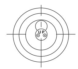
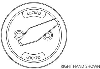
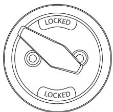
THUMBTURN INDICATOR RE-HANDING (DL2200 Series)
The thumbturn indicator is pre-configurated for Right Hand doors. See next steps to change handing for Left Hand Doors.
Position the inside thumbturn assembly as shown. While holding the ring in place. Push thumbturn in and rotate until the wheel clicks into the "L" (Left) on the opposite side.
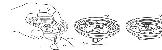
Rotate thumbturn to verify the mechanism operates correctly.
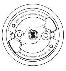
LEFT HAND SHOWN