Corbin Russwin DL2100 and DL3100 Series Deadbolt Locks Installation Instructions_FM200
Open the original PDF document
View PDF

DL 2100 & DL 3100 SERIES
Deadbolt Installation SEE REVERSE SIDE FOR DL 3100 IC CORE SERIES
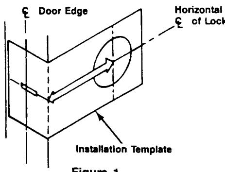
1 INSTALL DEADBOLT
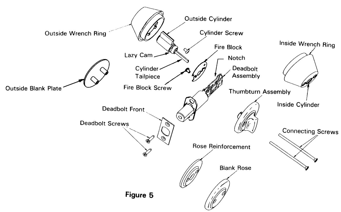
- a) Insert deadbolt unit into hole in door edge. (Make sure notched area is up. See Figure 5.) Fasten deadbolt to door with two attaching screws.
- b) For fire rated installations, remove screw from deadbolt tail and use to install Fire Block.
- c) IMPORTANT: Using screwdriver, rotate slot in hub to horizontal position to retract deadbolt.
- For outside cylinder function, go to next step. If outside blank plate is used, go to step 2b.
-
2 INSTALL CYLINDER(S). DO NOT insert keys in cylinder(s) at this time.
- a) Insert OUTSIDE cylinder into backside of the OUTSIDE Wrench Ring (No mounting holes in face) and secure with Cylinder Screw, if required. Holding the assembly horizontally ("ACCOUNTY") on wrench ring face is upright) rotate the cylinder tailpiece to the horizontal position. Insert outside assembly into door with cylinder tailpiece going through slot in hub of deadbolt tail.
- b) For installation of inside cylinder function, see step 2c; for inside thumbturn function, see step 2d; and for blank rose, see step 2e.
- c) Insert INSIDE cylinder into backside of the INSIDE Wrench Ring (Two mounting holes in face) and secure with Cylinder Screw, if required. Holding the assembly horizontally ("CONTINE"" on wrench ring face is upright) rotate lazy cam to the horizontal position. Align the lazy cam with the cylinder tailpiece from outside cylinder and slide assembly up to surface of door. Go to step 2e.
- d) Rotate thumbturn so that the word "LOCKED" is covered. Align slotted hole on back of thumbturn with cylinder tailpiece from outside cylinder. Slide assembly up to surface of door.
- e) Insert the two connecting screws through the inside wrench ring or rose, through the deadbolt tail and thread into the back of the outside wrench ring or plate. Tighten to provide a snug fit of both cylinder assemblies to the door.
- f) IMPORTANT: At this point operate deadbolt from both sides of door to check installation. DO NOT FORCE. If binding occurs, recheck the door preparation and complete installation procedure.
- g) When deadbolt operates smoothly, tighten both connecting screws securely.
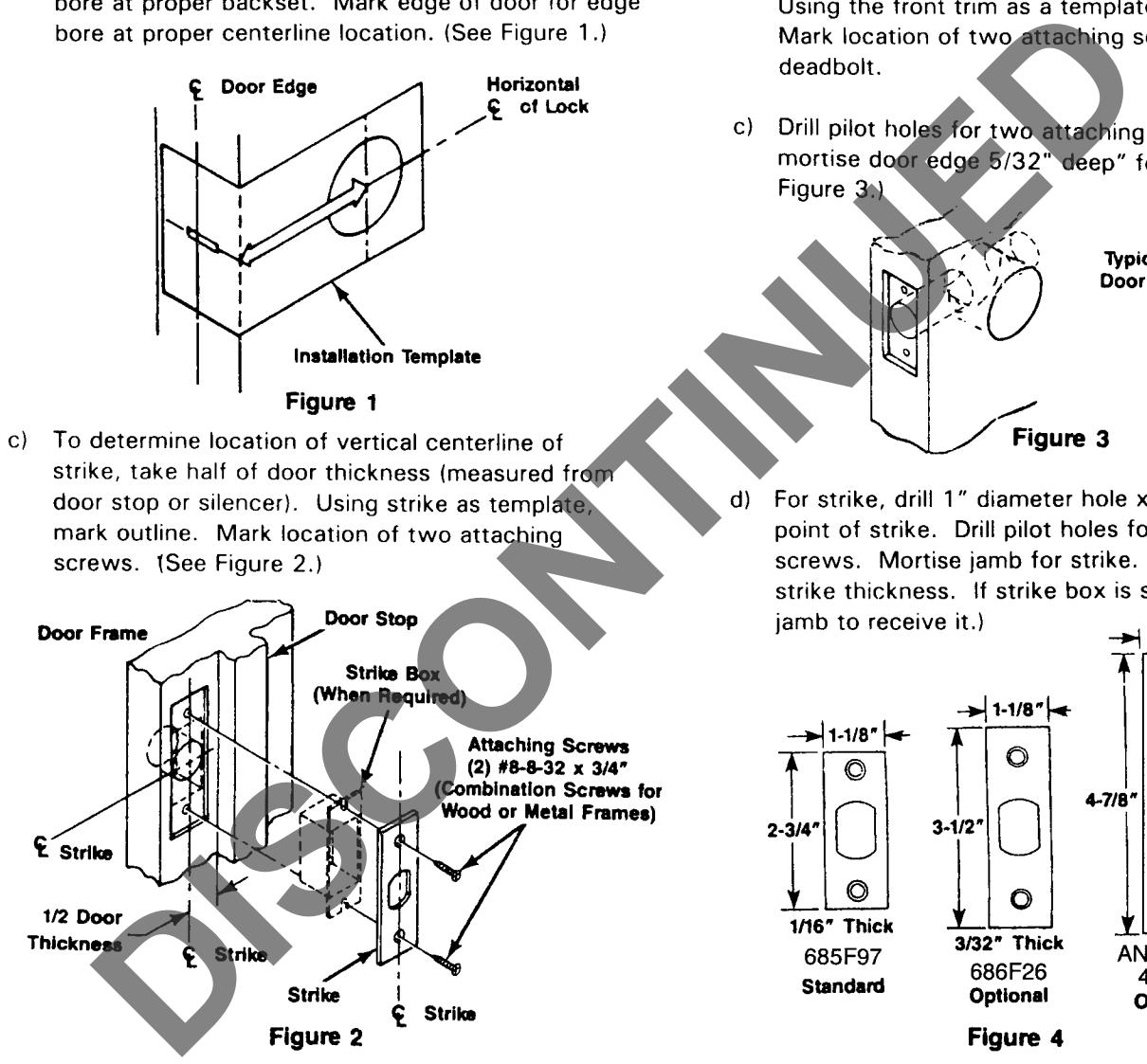
3 INSTALL STRIKE
a) Attach strike to jamb using two attaching screws.
DL 3100 IC CORE SERIES
Deadlock Installation
1 INSTALL DEADBOLT
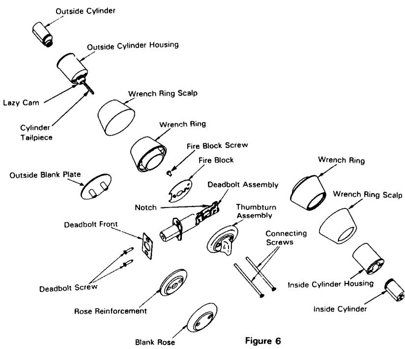
- a) Insert deadbolt unit into hole in door edge. (Make sure notched area is up. See Figure 6) Fasten deadbolt to door with two attaching screws.
- b) For fire rated installations, remove screw from deadbolt tail and use to install Fire Block.
- c) IMPORTANT: Using screwdriver, rotate slot in hub to horizontal position to retract deadbolt.
- For outside cylinder function, go to next step. If outside blank plate is used, go to step 2b.
-
2 INSTALL CYLINDER(S). DO NOT insert keys in cylinder(s) at this time.
- a) Insert OUTSIDE Cylinder Assembly (No mounting holes in face) into Wrench Ring and Scalp Assy. Holding the assembly horizontally (海亞拉爾 on wrench ring face is upright) rotate the cylinder tailpiece to the horizontal position. Insert outside assembly into door with the cylinder tailpiece going through slot in hub of deadbott tail.
- For installation of inside cylinder function, see step 2c; for inside thumbturn function, see step 2d; and for blank rose, see step 2e.
- c) Insert INSIDE cylinder (Two mounting holes in face) into Wrench Ring and Scalp Assembly, i required. Holding the assembly horizontally (黃金雄物 on wrench ring face is upright) rotal lazy cam to the horizontal position. Align the lacam with the cylinder tailpiece from outside cylinder and slide assembly up to surface of door. Go to step 2e.
- d) Rotate thumbturn so that the word "LOCKED" is covered. Align slotted hole on back of thumbturn with cylinder tailpiece from outside cylinder. Slide assembly up to surface of doo
- e) Insert the two connecting screws through the inside wrench ring or rose, through the deadboit tail and thread into the back of the outside wrench ring or plate. Tighten to provide a snug fit of both cylinder assemblies to the door.
- f) IMPORTANT: At this point operate deadbolt from both sides of door to check installation. DO NOT FORCE. If binding occurs, recheck the door preparation and complete installation procedure.
- When deadbolt operates smoothly, tighten both connecting screws securely.
3 INSTALL STRIKE
Attach strike to jamb using two attaching screws.
TAILPIECE PART NUMBERS BY LENGTH
| Part Number | Decimal Fraction | |
|---|---|---|
| 686F208 | 1.340 | 1-11/32" |
| 689F848 | 1.160 | 1-5/32" |
| 689F858 | 1.410 | 1-13/32" |
| 689F868 | 1.660 | 1-11/16" |
| 689F878 | 1.022 | 1-1/32" |
| 689F828 | 1.586 | 1-19/32" |
| 689F888 | 0.785 | 25/32" |
| 689F898 | 1.277 | 1-9/32" |
TAILPIECE LENGTH APPLICATIONS CHART
| List Numbers | 1-3/8" Door | 1-3/4" Door | 2" Door | 2-1/4" Door |
|---|---|---|---|---|
| DL 2113/DL 2117 | 1-11/32" | 1-11/32" | 1-11/16" | 1-11/16" |
| DL 3113 C6/DL 3117 C6 | N/A | 1-11/32" | 1-11/32" | 1-11/16" |
| DL 2112 | 25/32" | 1-5/32" | 1-13/32" | 1-11/16" |
| DL 3112 C6 | N/A | 25/32" | 1-1/32" | 1-9/32" |
| DL 2111 | 25/32" | 1-5/32" | 1-13/32" | 1-11/16" |
| DL 3111 C6 | N/A | 1-5/32" | 1-11/32" | 1-11/32" |
| DL 2160 | 1-19/32" | 1-19/32" | 1-19/32" | 1-19/32" |

In U.S.: Corbin Russwin, Inc. 225 Episcopal Road, Berlin, CT 06037 USA Phone: 860-225-7411 Fax: 860-828-7266
In Canada: Yale-Corbin Canada LTD. 3160 Orlando Drive, Mississauga, Ontario, Canada L4V1R5 Phone: 905-672-6220 Fax: 905-672-9022