Corbin Russwin DC8230 and DC8240 Series Slide Track Installation Instructions_80-9380-8006-152
Open the original PDF document
View PDFInstallation Instructions

DC8200 Series
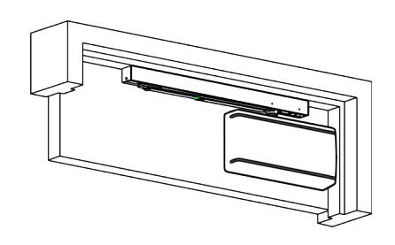
Universal Door Closers Slide Track Application
(100° Maximum Door Swing) A1 Hold Open Bumper Stop DC8230 Series Multi-Sized 1 through 6 and DC8240 Series Half-Size 1 through 6
IMPORTANT:
- An improperly installed or incorrectly adjusted door closer may cause property damage and/or personal injury; and will void product warranty.
- To avoid personal injury, DO NOT DISASSEMBLE THIS DOOR CLOSER BODY.
- Door closers must be securely fastened to a properly reinforced door and frame with fasteners provided.
- Door closers with the "A1" Hold Open Track options are not permitted to be installed in fire door assemblies.
BEFORE INSTALLING:


• ADA compliant closer: DC8230 and DC8240.
| Size of Door & Door Closer | |||||||
|---|---|---|---|---|---|---|---|
| Type of Installation | Interior |
Exterior
In-swinging |
Exterior Out-swinging |
Recommended
Closer size |
**Max. Opening
Force (lbs/f) |
||
|
Pull Side
Mounting |
2'6" | _ | _ | 1 | 8 | ||
| 3'0" | 2'6" | _ | 2 | 14 | |||
| 3'6" | 3'0" | _ | 3 | 16 | |||
| 4'0" | 3'6" | _ | 4 | 22 | |||
| _ | 4'0" | _ | 5 | 24 | |||
| _ | _ | _ | 6 | 26 | |||
|
Push Side
Mounting |
2'6" | _ | _ | 1 | 8 | ||
| 3'0" | _ | 2'6" | 2 | 14 | |||
| 3'6" | _ | 3'0" | 3 | 16 | |||
| 4'0" | _ | 3'6" | 4 | 22 | |||
| _ | _ | 4'0" | 5 | 24 | |||
| _ | _ | _ | 6 | 26 | |||
To Determine Hand of Door: RHR LEFT HAND DOOR DOOR RIGHT HAND DOOR
** These forces are for standard templating with bearing type hinges and do not account for pressure differentials and drafts.

A WARNING
This product can expose you to lead which is known to the state of California to cause cancer and birth defects or other reproductive harm. For more information go to www.P65warnings.ca.gov.
Attention Installer: Improper installation may result in damage to the product and void the factory warranty.
For installation assistance contact Corbin Russwin 1-800-543-3658 • techsupport.corbinrusswin@assaabloy.com
Copyright @ 2006, 2009, 2022, ASSA ABLOY Access and Egress Hardware Group, Inc. All rights reserved. Reproduction in whole or in part without the express written permission of ASSA ABLOY Access and Egress Hardware Group, Inc. is prohibited.
Experience a safer and more open world
DC8210 with A11 or A12 Unitrol Arm Installation
Russwin //
ASSA ABLO
Installation Instructions
1
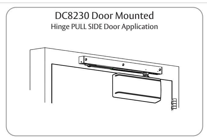
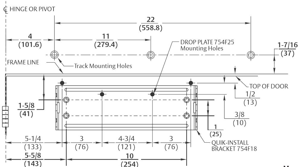
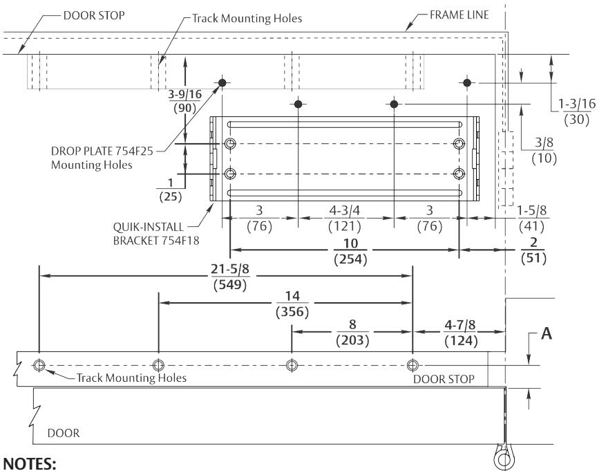
DC8230 Pull Side Track Installation
A. Template
Mark Door and Jamb (for QUIK-INSTALL® bracket and track)
- Door will travel an additional 5° to dead stop.
- Door hold open position adjustable from 85° to 120° of door opening.
|
Door
Thickness |
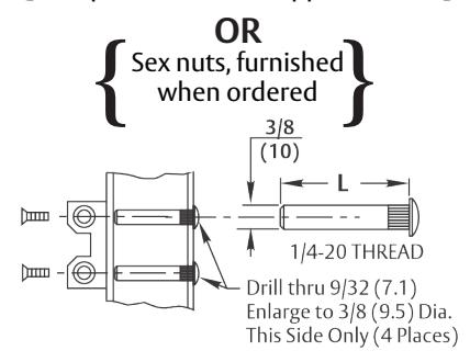
Sex Nut
Length "L" |
|
|---|---|---|
| 1-3/8 (35) | 1-9/32 (33) | |
|
1-3/4 (44)
& Over |
1-21/32 (42) | |
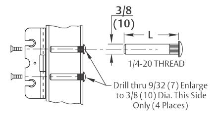
Mounting Screw Specifications Arm and QUIK-INSTALL Bracket
#12-14 self-drilling screw 1/8 (3) diameter pilot hole required for Wood Applications
Sex nuts, furnished when ordered
NOTES:
- Check hand of door (Refer to page 1)
- Right hand application shown. Left hand opposite.
- Dimensions given in inches (mm). Do not scale drawing.
- Closer must be installed in a true horizontal plane to ensure proper closer performance.
- Minimum clearance required over door: 2 (51).
- Minimum top rail: Without drop plate 3 (76), with drop plate 1-1/4 (32).
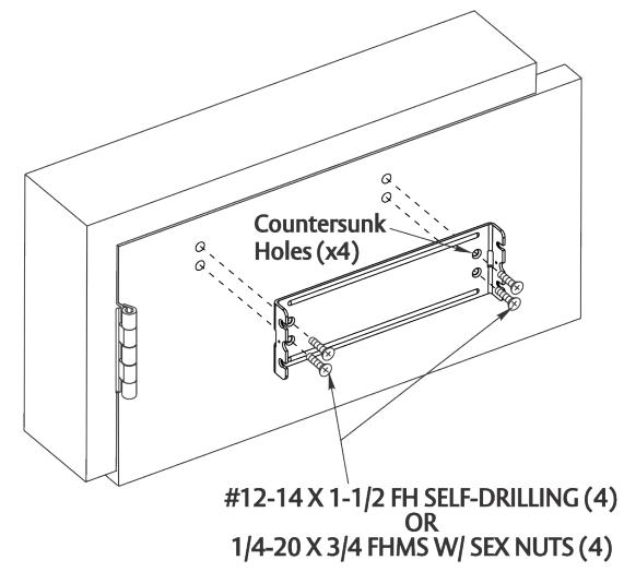
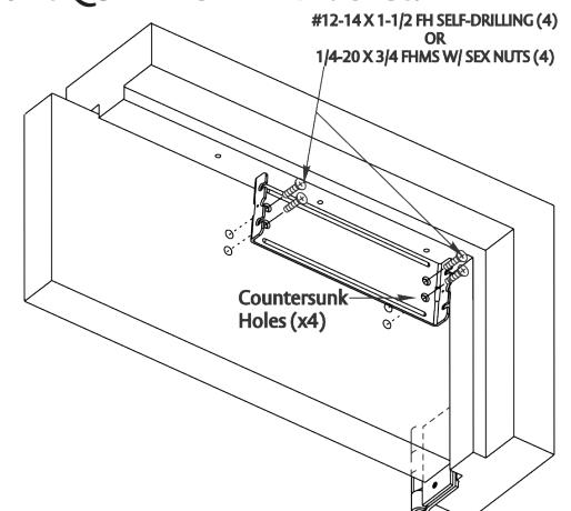
B. Mount QUIK-INSTALL Bracket.
For installation assistance contact Corbin Russwin 1-800-543-3658 • techsupport.corbinrusswin@assaabloy.com
Copyright @ 2006, 2009, 2022, ASSA ABLOY Access and Egress Hardware Group, Inc. All rights reserved. Reproduction in whole or in part without the express written permission of ASSA ABLOY Access and Egress Hardware Group, Inc. is prohibited.
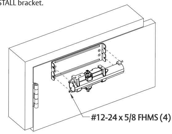
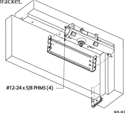
C. Mount Closer Body to QUIK-INSTALL Bracket.
- Start the four (4) mounting screws into the four (4) closer mounting holes.
- Place the closer onto the QUIK-INSTALL bracket with the four (4) mounting screws inserted in the four (4) QUIK-INSTALL bracket slots.
- Tighten the four (4) mounting screws to fasten the closer body to the QUIK-INSTALL bracket.
80-9380-8006-152 Rev 3 11/22
Experience a safer and more open world
DC8210 with A11 or A12 Unitrol Arm Installation
Installation Instructions
1 DC8230 Pull Side Track Installation (cont.)
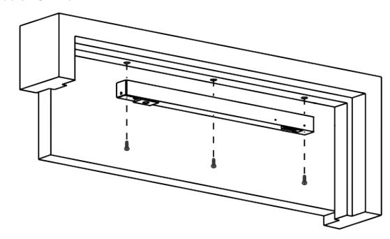
D. Attach track to frame.
With the spring buffer toward hinge edge of frame and open side facing down, fasten track assembly to frame as shown.
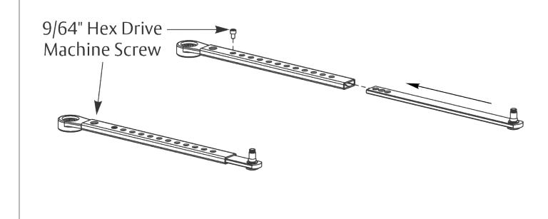
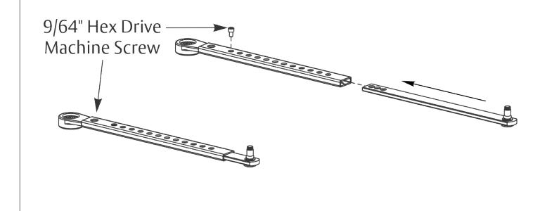
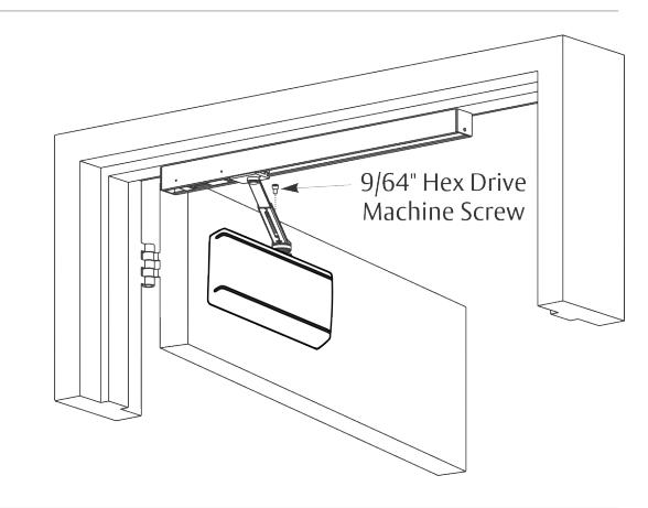
E. Adjust arm to shortest length.
Install 9/64" hex drive socket head screw from screw pack to the arm's shortest length as shown below.
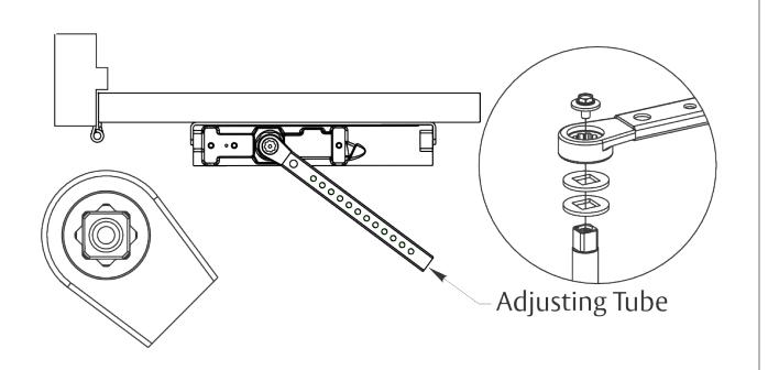
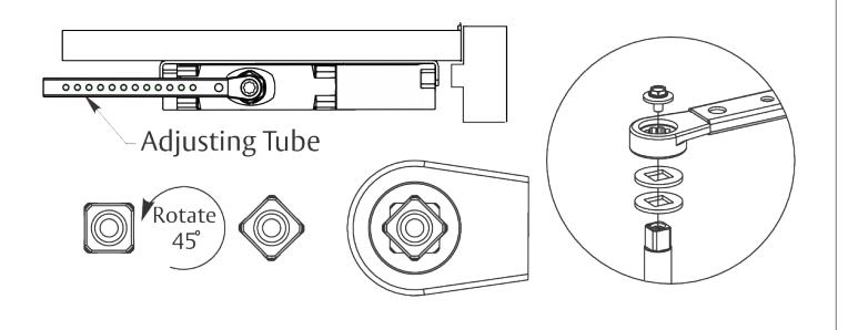
F. Place slide arm on pinion shaft.
Place the slide arm and two washers on the pinion shaft, indexed as shown below.
Secure the arm with the arm screw and washer as indicated.
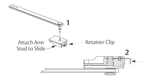
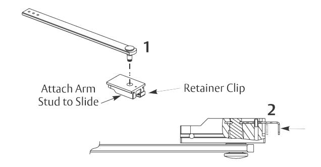
G. Insert arm stud into slide block.
- 1. Insert the arm stud into the slide block of the track assembly.
- 2. Secure the arm stud by pushing in the retainer clip that extends from the slide block in the track until it is flush with the slide block.
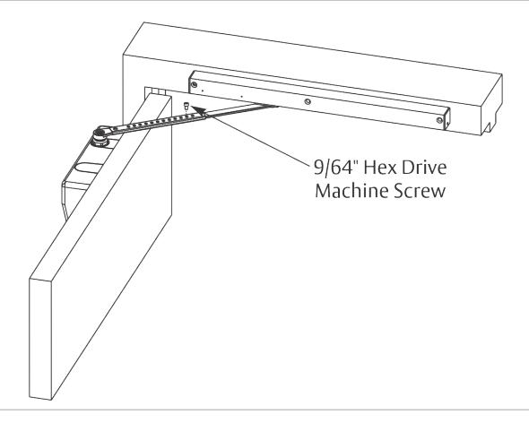
H. Adjust door opening / hold open angle.
Open the door until the slider is against the cushioned stop or engaged in hold open (A1 option only).
Remove the 9/64" hex drive socket head screw from the arm.
Open the door to the desired angle and install the hex drive screw into the adjusting rod hole that is aligned with the hold in the adjusting tube.
80-9380-8006-152 Rev 3 11/22 For installation assistance contact Corbin Russwin 1-800-543-3658 • techsupport.corbinrusswin@assaabloy.com
Copyright © 2006, 2009, 2022, ASSA ABLOY Access and Egress Hardware Group, Inc. All rights reserved. Reproduction in whole or in part without the express written permission of ASSA ABLOY Access and Egress Hardware Group, Inc. is prohibited.
I. Adjust closer: Refer to page 6 J. Engage/Disengage Hold Open (A1 Option only): Refer to page 7
3
DC8210 with A11 or A12 Unitrol Arm Installation
Installation Instructions
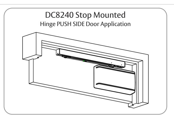
DC8240 Push Side Track Installation
A. Template
Mark Door and Stop (for QUIK-INSTALL® bracket and track)
- Door will travel an additional 5° to dead stop.
- Door hold open position adjustable from 85° to 110° of door opening.
- Check hand of door (Refer to page 1)
- Right hand application shown. Left hand opposite.
- Dimensions given in inches (mm). Do not scale drawing.
- Closer must be installed in a true horizontal plane to ensure proper closer performance.
- Minimum stop width: Refer to "Dimension A" in the chart.
- Minimum top rail: Without drop plate 5-1/2 (140), with drop plate 2-1/2 (64).
HINGE OR PIVOT ¢
ASSA ABLO
Mounting Screw Specifications Arm and QUIK-INSTALL Bracket
#12-14 self-drilling screw Type BSD 1/8 (3) diameter pilot hole required for Wood Applications
| Door Thickness | Sex Nut Length "L" | |
|---|---|---|
| 1-3/8 (35) | 1-9/32 (33) | |
| 1-3/4 (44) & Over | 1-21/32 (42) | |
Mount the track CENTERED on the Stop with the following minimum distances from the door side of the stop.
| Dimension A | Min Stop Width | |
|---|---|---|
| With drop plate | 1 (25) | 1-3/4 (45) |
| Without drop plate | 3/4 (19) | 1-1/2 (38) |
B. Mount QUIK-INSTALL Bracket.
For installation assistance contact Corbin Russwin 1-800-543-3658 • techsupport.corbinrusswin@assaabloy.com
Copyright © 2006, 2009, 2022, ASSA ABLOY Access and Egress Hardware Group, Inc. All rights reserved. Reproduction in whole or in part without the express written permission of ASSA ABLOY Access and Egress Hardware Group, Inc. is prohibited.
C. Mount Closer Body to QUIK-INSTALL Bracket.
- Start the four (4) mounting screws into the four (4) closer mounting holes.
- Place the closer onto the QUIK-INSTALL bracket with the four (4) mounting screws inserted in the four (4) QUIK-INSTALL bracket slots.
- Tighten the four (4) mounting screws to fasten the closer body to the QUIK-INSTALL bracket.
80-9380-8006-152 Rev 3 11/22
Experience a safer and more open world
DC8210 with A11 or A12 Unitrol Arm Installation
Installation Instructions
2 DC8240 Push Side Track Installation (cont.)
D. Attach track to frame.
With the spring buffer toward hinge edge of frame and open side facing down, fasten track assembly to frame as shown.
E. Adjust arm to shortest length.
Install 9/64" hex drive socket head screw from screw pack to the arm's shortest length as shown below.
F. Place slide arm on pinion shaft.
Place the slide arm and two washers on the pinion shaft, indexed as shown below.
Secure the arm with the arm screw and washer as indicated.
G. Insert arm stud into slide block.
- 1. Insert the arm stud into the slide block of the track assembly.
- 2. Secure the arm stud by pushing in the retainer clip that extends from the slide block in the track until it is flush with the slide block.
H. Adjust door opening / hold open angle.
Open the door until the slider is against the cushioned stop or engaged in hold open (A1 option only).
Remove the 9/64" hex drive socket head screw from the arm.
Open the door to the desired angle and install the hex drive screw into the adjusting rod hole that is aligned with the hold in the adjusting tube.
80-9380-8006-152 Rev 3 11/22 For installation assistance contact Corbin Russwin 1-800-543-3658 • techsupport.corbinrusswin@assaabloy.com
Copyright © 2006, 2009, 2022, ASSA ABLOY Access and Egress Hardware Group, Inc. All rights reserved. Reproduction in whole or in part without the express written permission of ASSA ABLOY Access and Egress Hardware Group, Inc. is prohibited.
I. Adjust closer: Refer to page 6 J. Engage/Disengage Hold Open (A1 Option only): Refer to page 7
5
DC8210 with A11 or A12 Unitrol Arm Installation
Installation Instructions
I. Adjust Closer
Spring Adjustment Power
Locate spring power adjuster from illustration below.
DC8200 Size 1 thru 6 Spring Power Adjustment Chart
- y All DC8200 closers are factory set at an approximate Size 3.
- y Adjust closer as needed for door size using this chart.
- y Readjustment may be required to suit prevailing conditions.
| Size of Door | Spring Power Adjustment | |||
|---|---|---|---|---|
| Interior |
Exterior In
Swing |
Exterior Out
Swing |
(No. of Full turns Clockwise) | Approx. Equivalent Closer Size |
| 2' 4" (712) | 2' 6" (764) | — | 2 – 7 | 3 |
| 2' 6" (764) | 3' 0" (915) | — | 7 – 11 | 4 |
| 3' 0" (915) | 3' 6" (1067) | 2' 6" (764) | 11 – 15 | 5 |
| 3' 6" (1067) | 4' 0" (1219) | 3' 0" (915) | 15 – 17 | 6 |
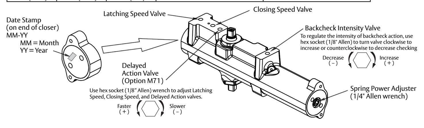
Closing Speed Valve (1/8" Allen Wrench Provided)
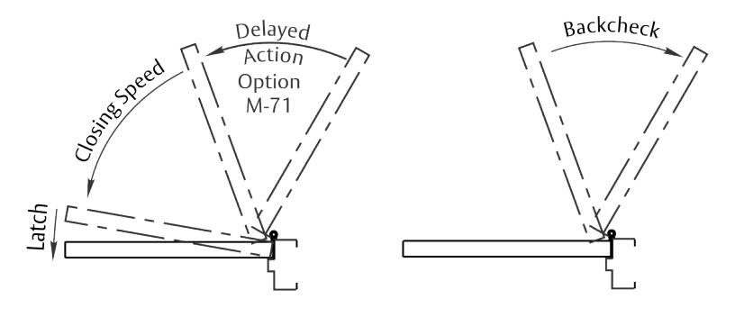
To adjust speed of door closing from fully open to a position 2" to 5" from closed, turn Closing Speed Valve CLOCKWISE to SLOW closing, COUNTERCLOCKWISE to SPEED closing.
Latching Speed Valve (1/8" Allen Wrench Provided)
After closing speed has been obtained, turn latching speed valve CLOCKWISE to SLOW latching or COUNTERCLOCKWISE to SPEED latching for last 2" to 5" of door travel.
NOTE: Set combination of CLOSING and LATCHING speeds to between 3 and 7 seconds. Use of door by handicapped, elderly, or small children may require even greater closing time.
Delayed Action Valve (1/8" Allen Wrench Provided)
Turn valve CLOCKWISE to SLOW closing, COUNTERCLOCKWISE to SPEED closing. Delayed action may be adjusted from 20 seconds to 90 seconds, depending on degree of door swing. Delay occurs at the beginning of the door closing cycle from fully open down to 70°, where the closing speed valve then begins its control.
Backcheck Intensity Valve (1/8" Allen Wrench Provided)
Turn valve COUNTERCLOCKWISE to reduce backcheck or CLOCKWISE to increase backcheck. (Backcheck should be set to give a soft cushioning action, not a sudden stop.)
For installation assistance contact Corbin Russwin 1-800-543-3658 • techsupport.corbinrusswin@assaabloy.com
Access and Egress Hardware Group, Inc. is prohibited.
80-9380-8006-152 Rev 3 11/22
DC8210 with A11 or A12 Unitrol Arm Installation
Installation Instructions
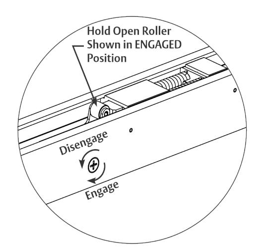
J. Engage/Disengage Hold open (A1 Option Only).
Hold Open models only :
Turn screw 1/2 revolution to Engage or Disengage Hold Open.

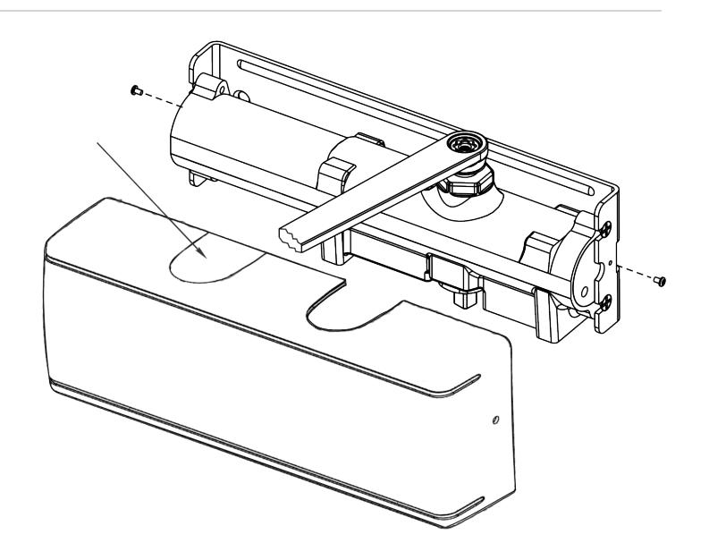
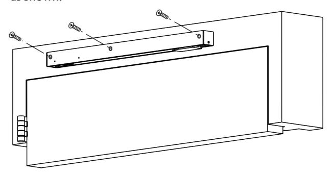
Installing Cover
- y Slip cover over closer.
- y Hold tightly against QUIK-INSTALL Bracket surface.
- y Secure on each side with 6-32 x 1/4" PBHMS screws.