Corbin Russwin DC8210 Series HD Parallel Arm Installation Instructions_80-9380-8001-152
Open the original PDF document
View PDFInstallation Instructions

DC8200 Series
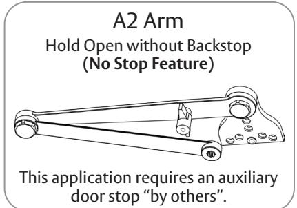
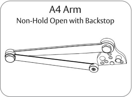
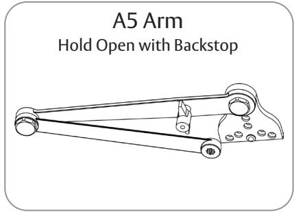
Universal Door Closer with Heavy Duty Parallel Arms (A2, A4, and A5)
DC8210 Series Multi-Sized from 1 through 6
IMPORTANT:
- An improperly installed or incorrectly adjusted door closer may cause property damage and/or personal injury ; and will void product warranty.
- To avoid personal injury, DO NOT DISASSEMBLE THIS DOOR CLOSER BODY.
- Door closers must be securely fastened to a properly reinforced door and frame with fasteners provided.
- Door and frame must be specifically templated for 85°, 90°, 100°, or 110° door swing.
- Door closers with a HOLD OPEN ARM are not permitted to be installed in fire door assemblies.
- Doors should be hung on ball bearing or anti-friction hinges/pivots.
- Door closer must not be installed on the exterior of a door in an exterior wall of a building.
| Size of Door & Door Closer | |||||||
|---|---|---|---|---|---|---|---|
|
Type of
Installation |
Interior |
Exterior
In-swinging |
Exterior Out-swinging |
Recommended
Closer size |
**Max. Opening
Force (lbs/f) |
||
|
Parallel
Arm |
2'4" | _ | _ | 1 | 8 | ||
| 2'6" | _ | _ | 2 | 14 | |||
| 3'0" | _ | 2'6" | 3 | 16 | |||
| 3'6" | _ | 3'0" | 4 | 22 | |||
| 4'0" | _ | 3'6" | 5 | 24 | |||
| 4'6" | _ | 4'0" | 6 | 26 | |||
| **These forces are for standard templating with bearing type hinges and do not account for pressure differentials and drafts. | |||||||
To Determine Hand of Door: RHR LEFT HAND DOOR DOOR RIGHT HAND DOOR
A WARNING
This product can expose you to lead which is known to the state of California to cause cancer and birth defects or other reproductive harm. For more information go to www.P65warnings.ca.gov.
Attention Installer: Improper installation may result in damage to the product and void the factory warranty.
For installation assistance contact Corbin Russwin 1-800-543-3658 • techsupport.corbinrusswin@assaabloy.com
Copyright © 2006, 2009, 2022, ASSA ABLOY Access and Egress Hardware Group, Inc. All rights reserved. Reproduction in whole or in part without the express written permission of ASSA ABLOY Access and Egress Hardware Group, Inc. is prohibited.
Experience a safer and more open world
⚠ WARNING
DC8210 with A2, A4, or A5 Heavy Duty Parallel Arm Installation
Corbin Russwin ASSA ABLOY
Installation Instructions
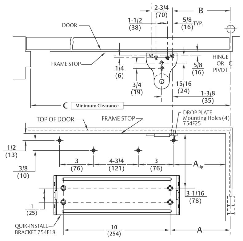
A. Mark door and Jamb (for QUIK-INSTALL® bracket and arm bracket)
Use template and dimensions charted.
|
Opening
Maximum |
A
QUIK-INSTALL Bracket |
Drop Plate |
B
Soffit Bracket |
C
Minimum Clearance |
|---|---|---|---|---|
| 85° | 8-3/4 (222) | 8-3/8 (213) | 12-7/16 (316) | 28-7/8 (733) |
| 90° | 7-3/4 (197) | 7-3/8 (187) | 11-1/2 (292) | 28 (711) |
| 100° | 6-1/4 (159) | 5-7/8 (149) | 10 (254) | 26-3/8 (670) |
| 110° | 4-7/8 (124) | 4-1/2 (114) | 8-5/8 (219) | 25-1/8 (638) |
NOTES:
- Check hand of door (Refer to page 1)
- Right hand application shown. Left hand opposite.
- Dimensions given in inches (mm). Do not scale drawing.
- Closer must be installed in a true horizontal plane to ensure proper closer performance.
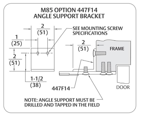
Mounting Screw Specifications Arm and QUIK-INSTALL Bracket
#12-14 self-drilling screw 1/8 (3) diameter pilot hole required for Wood Applications
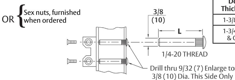
|
Door
Thickness |
Sex Nut
Length "L" |
|
|---|---|---|
| 1-3/8 (35) | 1-9/32 (33) | |
|
1-3/4 (44)
& Over |
1-21/32 (42) | |
For installation assistance contact Corbin Russwin 1-800-543-3658 • techsupport.corbinrusswin@assaabloy.com
(4 Places)
DC8200 Series
DC8210 with A2, A4, or A5 Heavy Duty Parallel Arm Installation
Installation Instructions
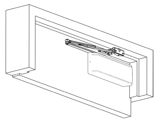
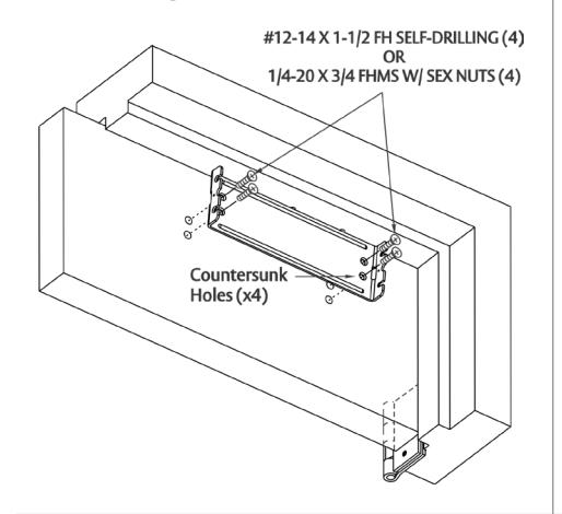
B. Mount QUIK-INSTALL Bracket.
-
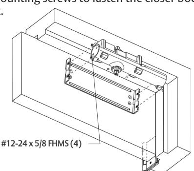
C. Mount Closer Body to QUIK-INSTALL Bracket.
y
Start the four (4) mounting screws into the four (4) closer mounting holes.
- y Place the closer onto the QUIK-INSTALL bracket with the four (4) mounting screws inserted in the four (4) QUIK-INSTALL bracket slots.
- y Tighten the four (4) mounting screws to fasten the closer body to the QUIK-INSTALL bracket.
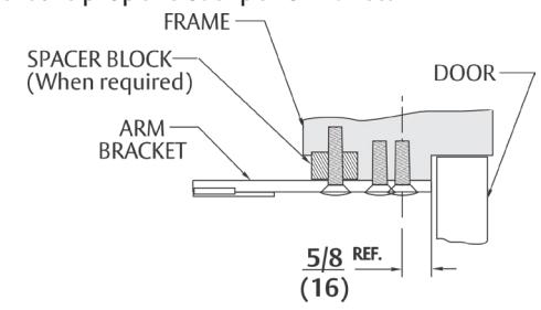
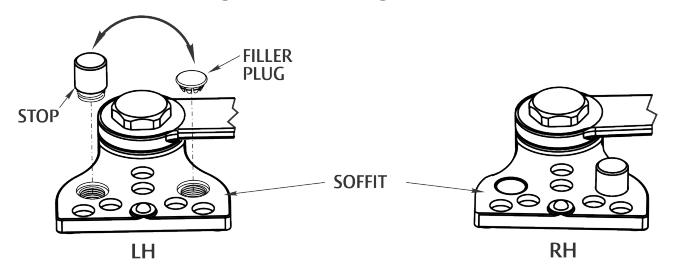
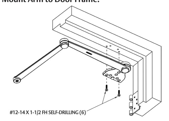
D. For Arms A4 and A5 Only: Handing Change. E. Mount Arm to Door Frame.
Arms are shipped for Left Hand Door.
To change handing:
- ‒ Remove from Soffit with 5/32 Allen Wrench.
- ‒ Remove Filler Plug.
- ‒ Switch Stop to opposite side and tighten.
- ‒ Push Filler Plug into remaining hole.
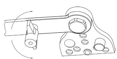
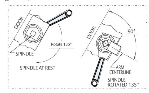
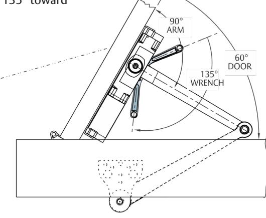
F. Connect Arm to Closer.
Using 1/8 hex wrench, turn Closing Speed Valve clockwise to close the valve. Do Not Overtighten! ( Refer to page 4 for valve location.)
‒ Open door to approximately 60°.
‒ Using wrench on the underside of spindle, rotate spindle approximately 135° toward hinge edge of door.
‒ Install arm on spindle at an approximate 90° angle to door.
‒ Reopen the Closing Speed Valve.
‒ Install and tighten 5/16 Hex Head Arm Washer and Screw Assembly.
80-9380-8001-152 Rev 3 12/22 For installation assistance contact Corbin Russwin 1-800-543-3658 • techsupport.corbinrusswin@assaabloy.com
Copyright © 2006, 2009, 2022, ASSA ABLOY Access and Egress Hardware Group, Inc. All rights reserved. Reproduction in whole or in part without the express written permission of ASSA ABLOY Access and Egress Hardware Group, Inc. is prohibited.

F. Adjust Closer
Spring Adjustment Power
Locate spring power adjuster from illustration below.
DC8200 Size 1 thru 6 Spring Power Adjustment Chart
- All DC8200 closers are factory set at an approximate Size 3.
- Adjust closer as needed for door size using this chart.
- Readjustment may be required to suit prevailing conditions.
| Size of Doo | r |
Spring Power
Adjustment |
Approx.
Equivalent |
|
|---|---|---|---|---|
| Interior | Exterior Exterior In Swing Out Swing |
(No. of Full turns
Clockwise) |
Closer Size | |
| 2' 4" (712) | 2' 6" (764) | _ | 2-7 | 3 |
| 2' 6" (764) | 3'0"(915) | _ | 7 – 11 | 4 |
| 3' 0" (915) | 3' 6" (1067) | 2' 6" (764) | 11 – 15 | 5 |
| 3' 6" (1067) | 4' 0" (1219) | 3' 0" (915) | 15 – 17 | 6 |
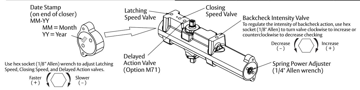
Closing Speed Valve (1/8" Allen Wrench Provided)
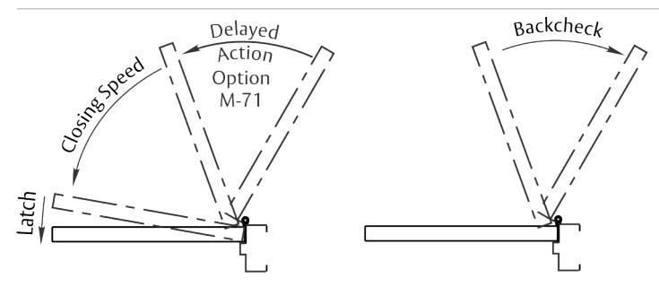
To adjust speed of door closing from fully open to a position 2" to 5" from closed, turn Closing Speed Valve CLOCKWISE to SLOW closing, COUNTERCLOCKWISE to SPEED closing.
Latching Speed Valve (1/8" Allen Wrench Provided)
After closing speed has been obtained, turn latching speed valve CLOCKWISE to SLOW latching or COUNTERCLOCKWISE to SPEED latching for last 2" to 5" of door travel.
NOTE: Set combination of CLOSING and LATCHING speeds to between 3 and 7 seconds. Use of door by handicapped, elderly, or small children may require even greater closing time.
Delayed Action Valve (1/8" Allen Wrench Provided)
Turn valve CLOCKWISE to SLOW closing, COUNTERCLOCKWISE to SPEED closing. Delayed action may be adjusted from 20 seconds to 90 seconds, depending on degree of door swing. Delay occurs at the beginning of the door closing cycle from fully open down to 70°, where the closing speed valve then begins its control.
Backcheck Intensity Valve
Turn valve COUNTERCLOCKWISE to reduce backcheck or CLOCKWISE to increase backcheck. (Backcheck should be set to give a soft cushioning action, not a sudden stop.)
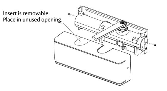
Installing Cover
- Slip cover over closer.
- Hold tightly against QUIK-INSTALL Bracket surface.
- Secure on each side with 6-32 x 1/4" PBHMS screws.
Hold Open Operation (A2 and A5 Arms Only)
A quarter turn of the tee handle in either direction engages or disengages the hold open feature.