Corbin Russwin DC8200 Series Regular Parallel Top Jamb Installation Instructions_80-9380-8000-152
Open the original PDF document
View PDFInstallation Instructions

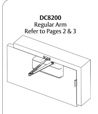
DC8200 Series
Universal Door Closer DC8210 Tri-Pack Standard 🕏
DC8200 Series Multi-Sized from 1 through 6
IMPORTANT:
- An improperly installed or incorrectly adjusted door closer may cause property damage and/or personal injury; and will void product warranty.
- To avoid personal injury, DO NOT DISASSEMBLE THIS DOOR CLOSER BODY.
- Door closers must be securely fastened to a properly reinforced door and frame with fasteners provided.
- Door closers with the "A1" HOLD OPEN ARM option are not permitted to be installed in fire door assemblies.
BEFORE INSTALLING:
- The Americans with Disabilities Act (ADA) requires that doors having door closers have an opening force not to exceed 5 lbf. Use standard templating for regular arm and parallel arm applications. Jamb mounted applications use the template for 140° door opening to achieve the required opening force.
- The door closer's power size adjustment feature may require adjustment to its lowest setting to comply with ADA opening force guidelines.
- An auxiliary door stop, by others, is strongly recommended to avoid damage to the door closer and adjacent property.
- Doors should be hung on ball bearing or anti-friction hinges/pivots.
- Door closer must not be installed on the exterior of a door in an exterior wall of a building.
- ADA compliant closers are: DC8200, DC8210, DC8220.
| Parallel Arm |
|---|
| Refer to Pages 4 & 5 |
DC8210
|
DC8220
Jamb Mount |
|---|
| Refer to Pages 6 & 7 |
| Size of Door & Door Closer | |||||||
|---|---|---|---|---|---|---|---|
|
Type of
Installation |
Interior |
Exterior
In-swinging |
Exterior
Out-swinging |
Recommended
Closer size |
**Max. Opening
Force (lbs/f) |
||
| 2'4" | _ | _ | 1 | 8 | |||
| 3'0" | _ | _ | 2 | 14 | |||
| Regular | 3'6" | 2'6" | 3'0" | 3 | 16 | ||
|
&
Top Jamb |
4'0" | 3'0" | 3'6" | 4 | 22 | ||
| 4'6" | 3'6" | 4'0" | 5 | 24 | |||
| 5'0" | 4'0" | 4'6" | 6 | 26 | |||
|
Parallel
Arm |
2'4" | _ | _ | 1 | 8 | ||
| 2'6" | _ | _ | 2 | 14 | |||
| 3'0" | _ | 2'6" | 3 | 16 | |||
| 3'6" | _ | 3'0" | 4 | 22 | |||
| 4'0" | _ | 3'6" | 5 | 24 | |||
| 4'6" | _ | 4'0" | 6 | 26 | |||
** These forces are for standard templating with bearing type hinges and do not account for pressure differentials and drafts.
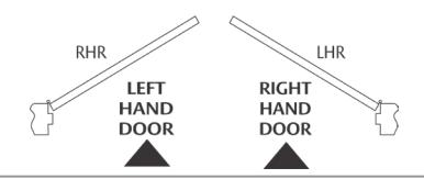
To Determine Hand of Door:
WARNING
A WARNING
Atte
This product can expose you to lead which is known to the state of California to cause cancer and birth defects or other reproductive harm. For more information go to www.P65warnings.ca.gov.
Attention Installer: Improper installation may result in damage to the product and void the factory warranty.
For installation assistance contact Corbin Russwin 1-800-543-3658 • techsupport.corbinrusswin@assaabloy.com
Copyright @ 2006, 2009, 2022, ASSA ABLOY Access and Egress Hardware Group, Inc. All rights reserved. Reproduction in whole or in part without the express written permission of ASSA ABLOY Access and Egress Hardware Group, Inc. is prohibited.
Experience a safer and more open world
Universal Door Closer
Installation Instructions

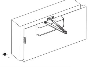
DC8200 Regular Arm Installation
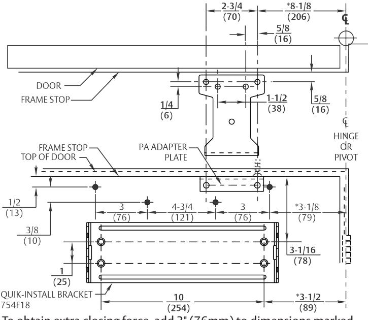
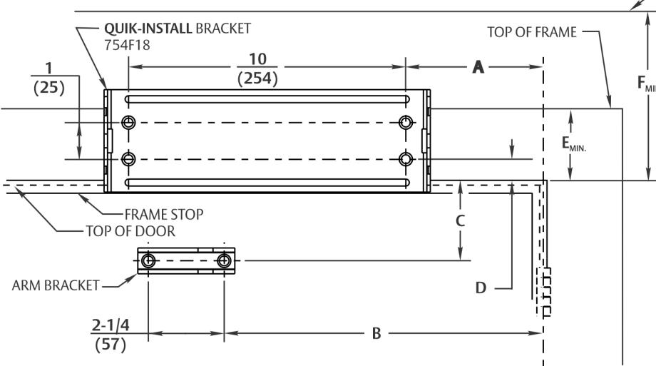
A. Template
Mark door and Jamb (for QUIK-INSTALL® bracket and arm bracket)
If top tail is 3" (76mm) or greater, use the template for the QUIK-INSTALL bracket provided. If top rail is 1-3/4" (44mm) to 2-15/16" (75mm), use DROP PLATE (754F20) dimensions, denoted by the 🕈
| (2 |
70)
-5/8 |
(57) | ARM | BRACKET |
Door
Thickness |
Sex Nut
Length "L" |
|
|---|---|---|---|---|---|---|---|
| HINGE OR DROP PLAT | —————————————————————————————————————— |
|
FRAME LINE | 1-3/8 (35) | 1-9/32 (33) | ||
| 4 754F20 | Holes (4) | 4,,, | TIO WILL EINE |
1-3/4 (44) &
over |
1-21/32 (42) | ||
|
1-5/8
(41) *5-1/4 (133) *5-5/8 (143) |
3 (76) |
4-3/4
(121) 10 (254) |
3 (76) |
1/2
(13) 3/8 (10) (25) QUIK-INSTALL BRACK 754F18 |
FDOOR | D |
8/8
10) 1/4-20 THREAD rill thru 9/32 (7) Enlarge o 3/8 (10) Dia. This Side Only (4 Places) |
* To obtain extra closing force, add 3" (76mm) to dimensions marked. This will limit the degree of door opening to 110°.
NOTES:
Check hand of door (Refer to page 1)
Right hand application shown. Left hand opposite.
Dimensions given in inches (mm). Do not scale drawing.
Closer must be installed in a true horizontal plane to ensure proper closer performance.
Door opening (up to 180°) is dependent upon door, frame, wall, and hinge/pivot conditions permitting.
Minimum clearance required over door:
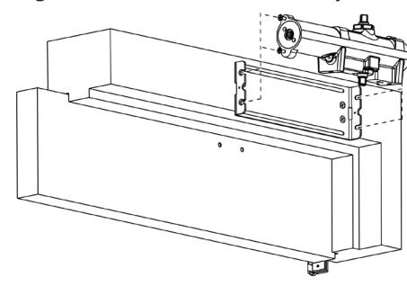
B. Mount QUIK-INSTALL Bracket
Non-Hold Open: 1-1/2 (39)
- Hold Open: 1-11/16 (43)
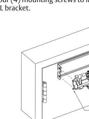
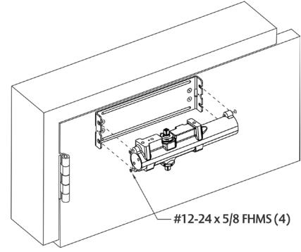
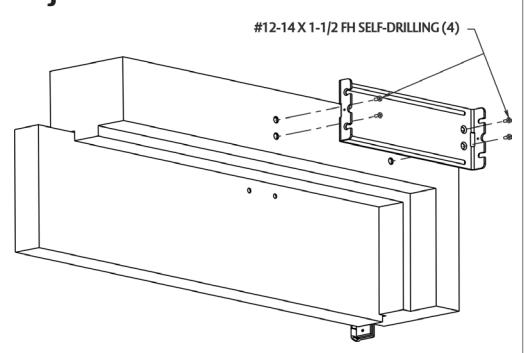
C. Mount Closer Body to QUIK-INSTALL Bracket
Mounting Screw Specifications
#12-14 self-drilling screw
1/8 (3) diameter pilot hole
required for Wood Applications
Arm and Closer Bracket
- Start the four (4) mounting screws into the four (4) closer mounting holes.
- Place the closer onto the QUIK-INSTALL bracket with the four (4) mounting screws inserted in the four (4) QUIK-INSTALL bracket slots.
- Tighten the four (4) mounting screws to fasten the closer body to the QUIK-INSTALL bracket.

Copyright © 2006, 2009, 2022, ASSA ABLOY Access and Egress Hardware Group, Inc. All rights reserved. Reproduction in whole or in part without the express written permission of ASSA ABLOY Access and Egress Hardware Group, Inc. is prohibited.
80-9380-8000-152 Rev 3 12/22
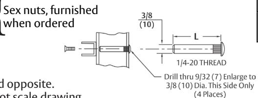
Sex nuts, furnished
when ordered
Experience a safer and more open world
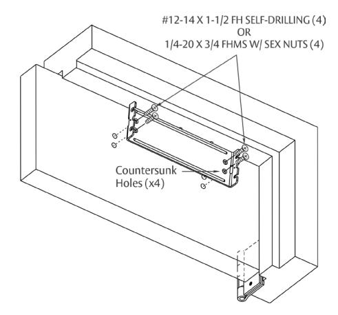
#12-14 X 1-1/2 FH SELF-DRILLING (4) 1/4-20 X 3/4 FHMS W/ SEX NUTS (4)
Universal Door Closer
Installation Instructions

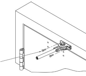
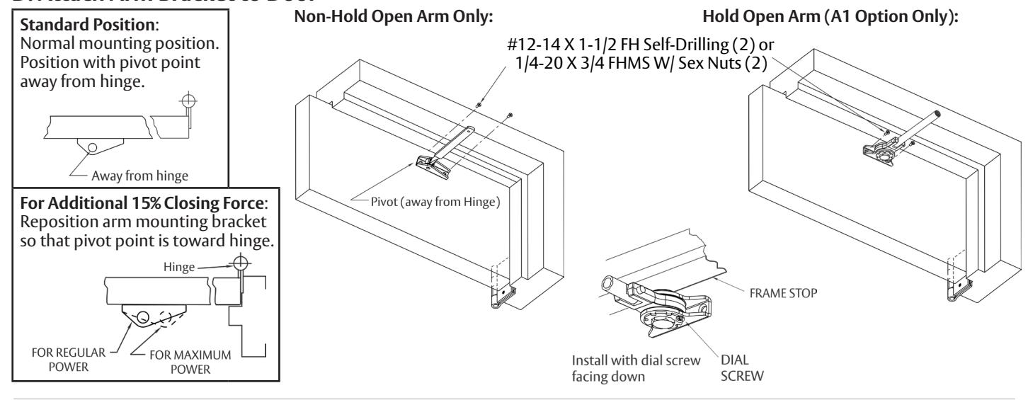
D. Attach Arm Bracket to Frame
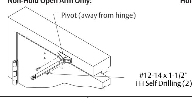
Non-Hold Open Arm Only: Hold Open Arm (A1 Option Only):
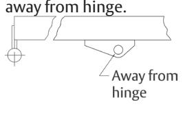
Standard Position :
Normal mounting position. Position with pivot point
For Additional 15% Closing Force :
Reposition arm mounting bracket so that pivot point is toward hinge.
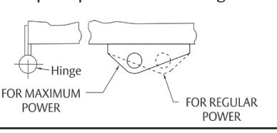
Hold Open Arm:
Position so that dial screw is on UNDERSIDE of bracket.
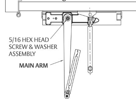
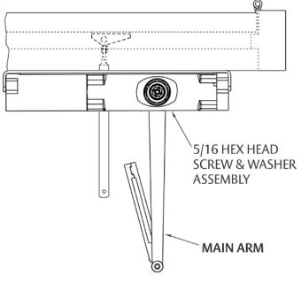
E. Position Arm on Closer
Non-Hold Open Arm Only:
Main arm projects straight out at 90° angle to door. Install and tighten arm screw & washer assembly.
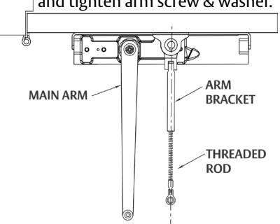
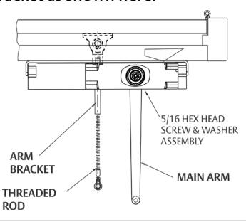
Hold Open Arm Only:
Main arm projects straight out at 90° angle to door. Remove arm screw and washer from elbow joint and disassemble arm. Thread the rod into the Arm Bracket as shown below. Install and tighten arm screw & washer.
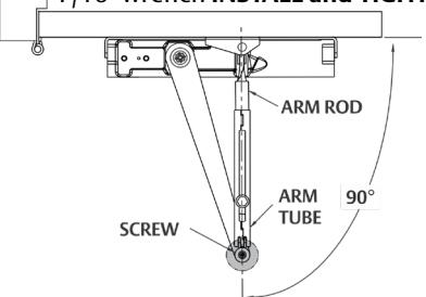
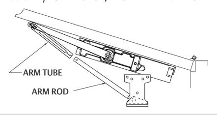
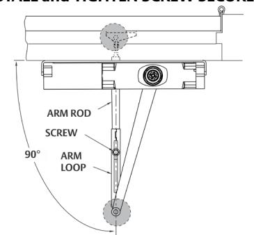
F. Preload and Adjust Arm
Non-Hold Open Arm Only:
Open door and slide arm rod into arm loop. Close door and swing the adjusting arm so it is 90° to frame. With 7/16" wrench INSTALL and TIGHTEN SCREW SECURELY .
Extended Maintenance
Lubricate Arm periodically at shaded points with a drop or two of appropriate lubricant. NOTE : When lubricating a Hold Open Arm, DO NOT use any lubricant on the Holding Surface components.
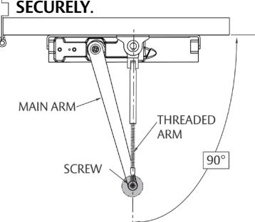
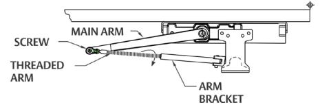
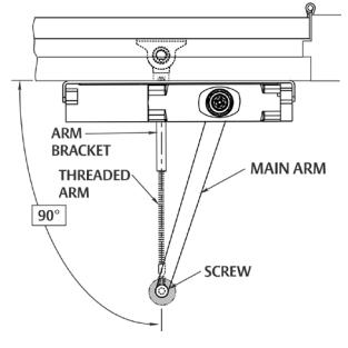
Hold Open Arm Only:
While door is closed, adjust the Threaded arm in the Arm bracket until the bearing fits back onto elbow joint on the Main Arm at 90° as shown below. RE-INSTALL AND TIGHTEN SCREW
3
G. Adjust Door Closer: Refer to Page 8
80-9380-8000-152 Rev 3 12/22 For installation assistance contact Corbin Russwin 1-800-543-3658 • techsupport.corbinrusswin@assaabloy.com
Copyright © 2006, 2009, 2022, ASSA ABLOY Access and Egress Hardware Group, Inc. All rights reserved. Reproduction in whole or in part without the express written permission of ASSA ABLOY Access and Egress Hardware Group, Inc. is prohibited.
Universal Door Closer
Installation Instructions

ASSA ABLOY
2
DC8210 Parallel Arm Installation
A. Template
Mark door and Jamb (for QUIK-INSTALL® bracket and adapter plate)
If top tail is 5-1/4" (133mm) or greater, use the template for the QUIK-INSTALL bracket provided. If top rail is 1-3/4" (44mm) to 5-1/8" (130mm), use DROP PLATE (754F25) dimensions, denoted by the +.
NOTES:
- Check hand of door (Refer to page 1)
- Right hand application shown. Left hand opposite.
- Dimensions given in inches (mm). Do not scale drawing.
- Closer must be installed in a true horizontal plane to ensure proper closer performance.
- Door opening (up to 180°) is dependent upon door, frame, wall, and hinge/pivot conditions permitting.
*To obtain extra closing force, add 3" (76mm) to dimensions marked. This will limit the degree of door opening to 110°.
Mounting Screw Specifications
Arm and Closer Bracket
#12-14 self-drilling screw 1/8 (3) diameter pilot hole required for Wood Applications

|
Door
Thickness |
Sex Nut
Length "L" |
|---|---|
| 1-3/8 (35) | 1-9/32 (33) |
|
1-3/4 (44)
& Over |
1-21/32 (42) |
B. Mount QUIK-INSTALL Bracket
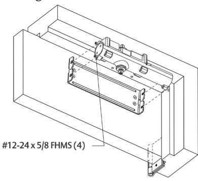
C. Mount Closer Body to QUIK-INSTALL Bracket
- Start the four (4) mounting screws into the four (4) closer mounting holes.
- Place the closer onto the QUIK-INSTALL bracket with the four (4) mounting screws inserted in the four (4) QUIK-INSTALL bracket slots.
- Tighten the four (4) mounting screws to fasten the closer body to the QUIK-IN-STALL bracket.
For installation assistance contact Corbin Russwin 1-800-543-3658 • techsupport.corbinrusswin@assaabloy.com
Copyright © 2006, 2009, 2022, ASSA ABLOY Access and Egress Hardware Group, Inc. All rights reserved. Reproduction in whole or in part without the express written permission of ASSA ABLOY Access and Egress Hardware Group, Inc. is prohibited.
80-9380-8000-152 Rev 3 12/22
Experience a safer and more open world
Universal Door Closer
Installation Instructions

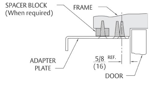
D. Mount Adapter Plate Bracket on Jamb
Using holes spotted on soffit or stop in Step A, mount adapter plate bracket.
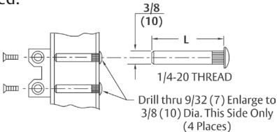
E. Attach Arm Bracket to Frame
F. Position Arm on Closer
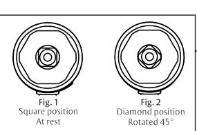
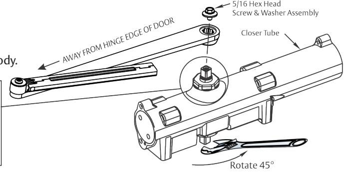
Using hex wrench provided, turn closing speed and latching speed valves clockwise until completely closed. DO NOT OVER TIGHTEN.
Using wrench, turn under side of spindle 45° toward the closer tube until it reaches the diamond position (Fig. 2).
Immediately place arm on spindle so that it is parallel to the closer body.
Install and tighten arm screw and washer assembly. Reopen valves.
G. Connect and Position Arms
Open door and slide arm rod into arm loop. Close door, swing arms so that they form a "V" position, as in Step H. With 7/16" wrench, INSTALL AND TIGHTEN SCREW SECURELY.
Hold Open Arm Only:
Remove main arm screw from elbow joint and disassemble arm. Thread the rod into the Arm Bracket as shown below. While door is closed, adjust the Threaded Arm in the Arm Bracket until the bearing fits back onto the elbow joint on the Main Arm and forms a "V" as shown below.
RE-INSTALL AND TIGHTEN SCREW SECURELY .
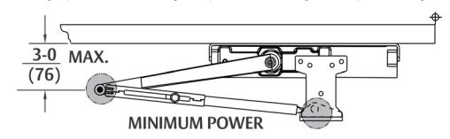
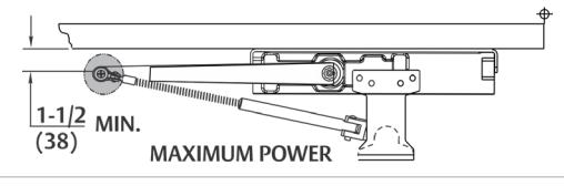
H. Power Adjustment
To increase the power of the closer, re-adjust the arm so it is nearer the door. To decrease power, re-adjust the arm so it is farther away from the door and then secure screw in arm loop (non-hold open) or elbow joint (hold open).
Extended Maintenance
5
Lubricate Arm periodically at shaded points with a drop or two of appropriate lubricant.
NOTE : When lubricating a Hold Open Arm, DO NOT use any lubricant on the Holding Surface components.
I. Adjust Door Closer: Refer to Page 8
80-9380-8000-152 Rev 3 12/22 For installation assistance contact Corbin Russwin 1-800-543-3658 • techsupport.corbinrusswin@assaabloy.com
Copyright © 2006, 2009, 2022, ASSA ABLOY Access and Egress Hardware Group, Inc. All rights reserved. Reproduction in whole or in part without the express written permission of ASSA ABLOY Access and Egress Hardware Group, Inc. is prohibited.
Universal Door Closer
ASSA ABLO
Installation Instructions
DC8220 Jamb Mount Installation
A. Template
Mark door and Jamb (for QUIK-INSTALL® bracket and adapter plate)
DO NOT USE THIS TEMPLATE WITH A DROP PLATE (754F24). Use the template addendum (80-9380-8009-152) included with 754F24 Drop Plate orders.
|
Opening
Maximum |
Α | В |
Hinge
Condition |
||
|---|---|---|---|---|---|
| 110° |
6-7/8
(175) |
14
(356) |
Butts, Offset | ||
| 140° |
5-1/8
(130) |
12-1/2
(318) |
Pivots, and
Swing Clear Hinges |
||
| 180° |
3-3/8
(86) |
10-1/2
(267) |
|||
| 140° |
5-1/8
(130) |
12-3/8
(314) |
*Center Hung | ||
Dimensions "A" and "B" are taken from centerline of hinge as shown and apply to pivot point of swing clear hinges. Offset and center hung pivots.
*Must be single acting door.
| 8 | |||||||
|---|---|---|---|---|---|---|---|
|
Header
Width |
С | D | E | F | |||
| Standard | 1-1/2 | 3/4 | 2-3/8 | 4 | |||
| (38) | (19) | (60) | (102) | ||||
| Narrow | 1-7/8 | 3/8 | 1-3/4 | 3-1/2 | |||
| (48) | (10) | (45) | (89) | ||||
| Door Thickness | Sex Nut Length "L" |
|---|---|
| 1-3/8 (35) | 1-9/32 (33) |
| 1-3/4 (44) & Over | 1-21/32 (42) |
Mounting Screw Specifications
Arm and Closer Bracket
#12-14 self-drilling screw 1/8 (3) diameter pilot hole required for Wood Applications

NOTES:
Check hand of door (Refer to page 1)
Right hand application shown. Left hand opposite.
Dimensions given in inches (mm). Do not scale drawing.
Closer must be installed in a true horizontal plane to ensure proper closer performance.
All degrees of door opening is dependent upon door, frame, wall, and hinge/pivot conditions permitting.
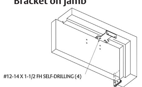
B. Mount QUIK-INSTALL Bracket to Jamb.
C. Mount Closer Body to QUIK-INSTALL Bracket.
• Start the four (4) mounting screws into the four (4) closer mounting holes.
CEILING LINE
• Place the closer onto the QUIK-INSTALL bracket with the four (4) mounting screws inserted in the four (4) QUIK-INSTALL bracket slots.
Tighten the four (4) mounting screws to fasten the closer body to the QUIK-INSTALL bracket.
For installation assistance contact Corbin Russwin 1-800-543-3658 • techsupport.corbinrusswin@assaabloy.com
Copyright © 2006, 2009, 2022, ASSA ABLOY Access and Egress Hardware Group, Inc. All rights reserved. Reproduction in whole or in part without the express written permission of ASSA ABLOY Access and Egress Hardware Group, Inc. is prohibited.
80-9380-8000-152 Rev 3 12/22
Experience a safer and more open world
6
Universal Door Closer
Installation Instructions

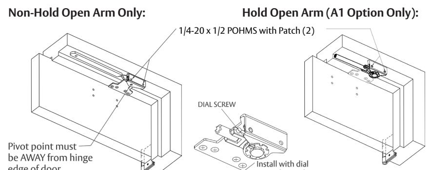
D. Attach Arm Bracket to Door
E. Position Arm on Closer
Non-Hold Open Arm Only:
Main arm projects straight out at 90° angle to door. Install and tighten arm screw & washer assembly.
Hold Open Arm Only:
Main arm projects straight out at 90° angle to door. Install and tighten arm screw & washer assembly. Remove main arm screw from elbow joint and disassemble arm. Thread the rod into the Arm Bracket as shown here.
F. Preload and Adjust Arm
Non-Hold Open Arm Only:
Open door and slide arm rod into arm loop. Close door, swing arms so adjusting arm is 90° to frame. With 7/16" wrench, INSTALL and TIGHTEN SCREW SECURELY .
Extended Maintenance Lubricate Arm periodically at shaded points with a drop or two of appropriate lubricant. NOTE : When lubricating a
Hold Open Arm, DO NOT use any lubricant on the Holding Surface components.
Hold Open Arm Only (A1 Option):
7
While door is closed, adjust the Threaded Arm in the Arm Bracket until the bearing fits back onto the elbow joint on the Main Arm at 90° as shown below.
RE-INSTALL and TIGHTEN SCREW SECURELY .
G. Adjust Door Closer: Refer to Page 8
80-9380-8000-152 Rev 3 12/22 For installation assistance contact Corbin Russwin 1-800-543-3658 • techsupport.corbinrusswin@assaabloy.com
Copyright © 2006, 2009, 2022, ASSA ABLOY Access and Egress Hardware Group, Inc. All rights reserved. Reproduction in whole or in part without the express written permission of ASSA ABLOY Access and Egress Hardware Group, Inc. is prohibited.
Approved 2022-12-12

4
DC8000 Closer Adjustment
Spring Adjustment Power
Locate spring power adjuster from illustration below.
DC8200 Size 1 thru 6 Spring Power Adjustment Chart
- All DC8200 closers are factory set at an approximate Size 3.
- Adjust closer as needed for door size using this chart.
- Readjustment may be required to suit prevailing conditions.
| Size of Door |
Spring Powe
(No. of Full tu |
Approx.
Equivalent |
|||
|---|---|---|---|---|---|
| Interior |
Exterior
In Swing |
Exterior
Out Swing |
Regular & TJ Parallel Arm Mounting Mounting | Closer Size | |
| 2' 4" (712) | 2' 6" (764) | _ | 1 – 5 | 2-7 | 3 |
| 2' 6" (764) | 3' 0" (915) | _ | 5-8 | 7 – 11 | 4 |
| 3' 0" (915) | 3' 6" (1067) | 2' 6" (764) | 8 – 13 | 11 – 15 | 5 |
| 3' 6" (1067) | 4' 0" (1219) | 3' 0" (915) | 13 – 15 | 15 – 17 | 6 |
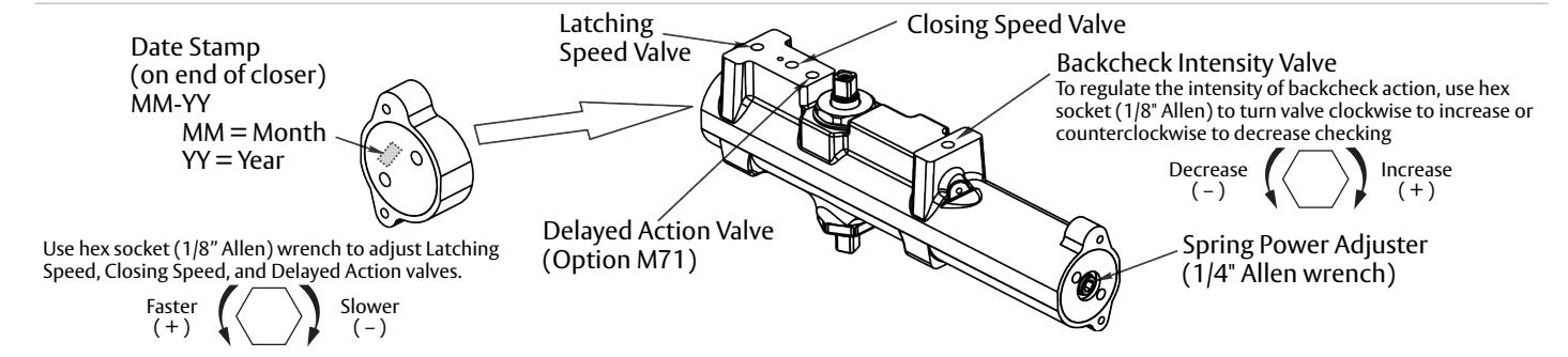
Closing Speed Valve (1/8" Allen Wrench Provided)
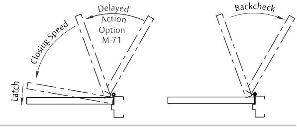
To adjust speed of door closing from fully open to a position 2" to 5" from closed, turn Closing Speed Valve CLOCKWISE to SLOW closing, COUNTERCLOCKWISE to SPEED closing.
Latching Speed Valve (1/8" Allen Wrench Provided)
After closing speed has been obtained, turn latching speed valve CLOCKWISE to SLOW latching or COUNTERCLOCKWISE to SPEED latching for last 2" to 5" of door travel.
NOTE: Set combination of CLOSING and LATCHING speeds to between 3 and 7 seconds. Use of door by handicapped, elderly, or small children may require even greater closing time.
Delayed Action Valve (1/8" Allen Wrench Provided)
Turn valve CLOCKWISE to SLOW closing, COUNTERCLOCKWISE to SPEED closing. Delayed action may be adjusted from 20 seconds to 90 seconds, depending on degree of door swing. Delay occurs at the beginning of the door closing cycle from fully open down to 70°, where the closing speed valve then begins its control.
Backcheck Intensity Valve
Turn valve COUNTERCLOCKWISE to reduce backcheck or CLOCKWISE to increase backcheck. (Backcheck should be set to give a soft cushioning action, not a sudden stop.)
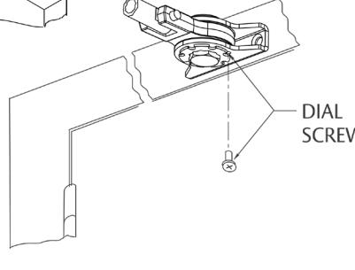
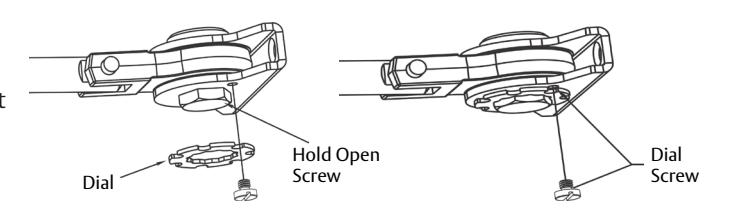
To Adjust Hold Open (A1 Option)
Open the door to desired position and tighten the hold open screw firmly (For RH application, turn screw on underside CLOCKWISE. For LH application, turn screw COUNTERCLOCKWISE.).
Place the hold open dial over the hex head of the bracket screw so that one of the slots in the dial is directly over small screw hole tapped in bracket. Seat the dial tightly over the bracket.
INSERT DIAL SCREW AND TIGHTEN SECURELY.
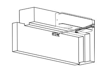
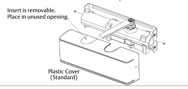
Installing Cover
- Slip cover over closer.
- Hold tightly against QUIK-INSTALL Bracket surface.
- Secure on each side with 6-32 x 1/4" PBHMS screws.
Experience a safer and more open world