Corbin Russwin DC6230 Series Hinge Side Door Application Installation Instructions
Open the original PDF document
View PDFUniversal Door Closers Slide Track Application
(110° Maximum Door Swing) (standard)- N.H.O. Bumper Stop A1 - H.O. Bumper Stop

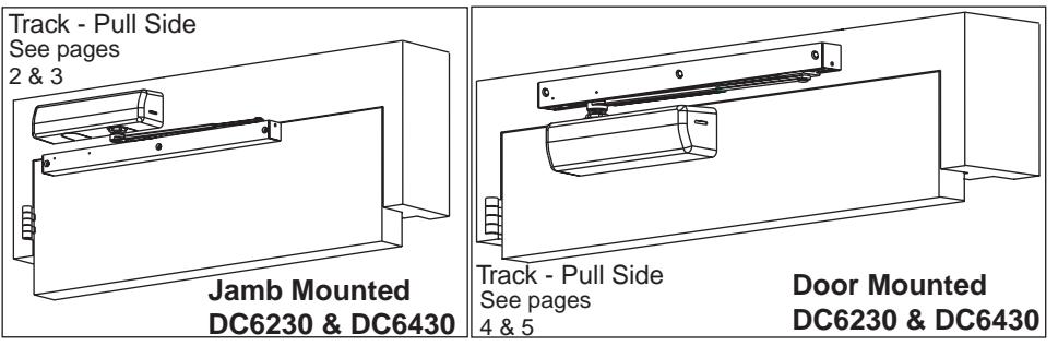
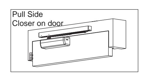
Hinge (Pull) Side Door Application
DC6230 Series Multi-Sized 1 thru 6
DC6430 Series Half-Size 1 thru 6
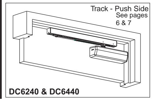
Opposite to Hinge (Push) Side Door Application
DC6240 Series Multi-Sized 1 thru 6
DC6440 Series
Half-Size 1 thru 6
The Habitat for Humanity®
IMPORTANT:
- An improperly installed or incorrectly adjusted door closer may cause property damage or personal injury; and will void product warranty.
- To avoid personal injury, DO NOT DISASSEMBLE THIS DOOR CLOSER BODY.
- Door closers must be securely fastened to a properly reinforced door and frame with fasteners provided.
- Door closers with the "A1" HOLD OPEN TRACK option are not permitted to be installed in fire door assemblies.
- With or without Slim Cover option, M76.
BEFORE INSTALLING:

- The Americans with Disabilities Act (ADA) states that doors having door closers require the opening force not to exceed 5 lbf. for interior doors.
- The door closer's power size adjustment feature may require adjustment to its lowest setting to comply with ADA opening force guidelines.
- ADA compliant closers are: DC6230 & DC6240.
| Size of Door & Door Closer | ||||||||
|---|---|---|---|---|---|---|---|---|
|
Type
of Installation |
Interior |
Exterior
In-swinging |
Exterior
Out-swinging |
Recommended
Closer Size |
**Max.
Opening Force Ibs/f |
|||
|
PULL
SIDE Mounting |
2'6"
3'0" 3'6" 4'0" |
2'6"
3'0" 3'6" *4'0" |
1
2 3 4 5 |
8
14 16 22 24 26 |
||||
|
PUSH
SIDE Mounting |
2'6"
3'0" 3'6" 4'0" |
2'6"
3'0" *3'6" *4'0" |
1
2 3 4 5 6 |
8
14 16 22 24 26 |
||||
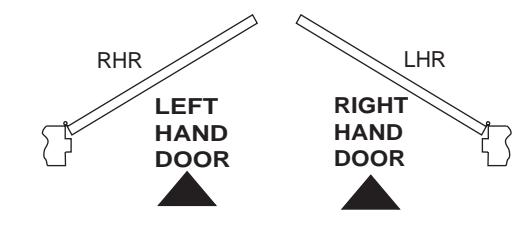
TO DETERMINE HAND OF YOUR DOOR:
* DC6400 Series Recommended
** NOTE: These forces are for standard templating with bearing type hinges and do not account for pressure differentials and draft. Half size closers DC6400 are capable of being adjusted to next higher power size.
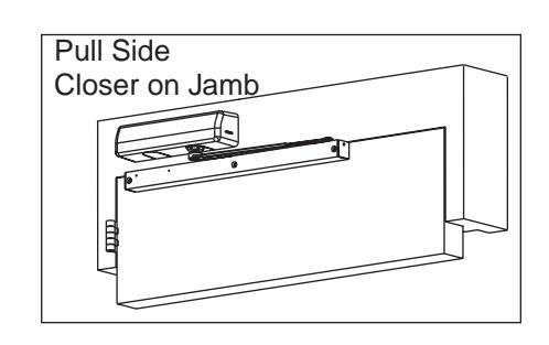
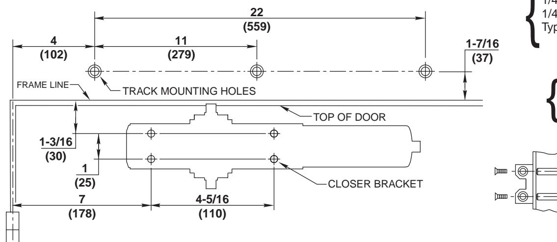
Pull Side, Jamb Mounted Closer Application DC6230 & DC6430 Series
1. Template
Mark Door and Jamb (for closer bracket and track)
- Door will travel additional 5° to dead stop.
- Door hold open position adjustable from 75° to 110° of door opening.
- Right Hand Application Shown. Left Hand Opposite.
- Dimensions given in inches (mm). Do Not Scale Drawing.
- Closer must be installed in a true horizontal plane to ensure proper closer performance.
- Door opening (up to 110°) is dependent upon door, frame, wall and hinge/pivot conditions permitting.
- Maximum 1/8 (3mm) hinge side frame reveal.
- 100° hold open position (A1)
- Clearance between door and wall must exceed 1-1/2 (38) with door at fully open position.
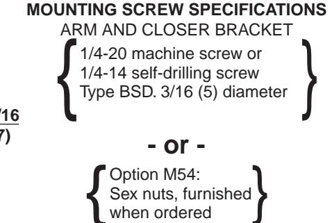
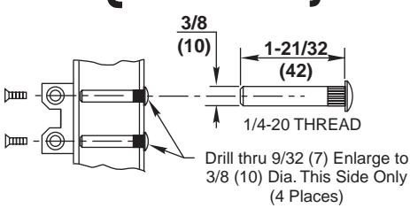
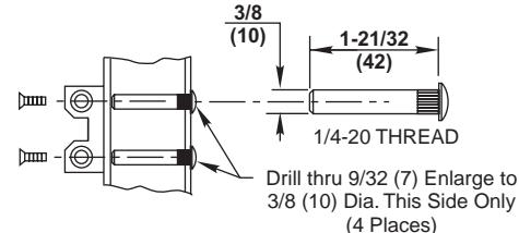
MOUNTING SCREW SPECIFICATIONS ARM AND CLOSER BRACKET
1/4-20 machine screw or 1/4-14 self-drilling screw Type BSD. 3/16 (5) diameter Option M54: Sex nuts, furnished when ordered
Pull Side, Jamb Mounted Closer Application (Continued)
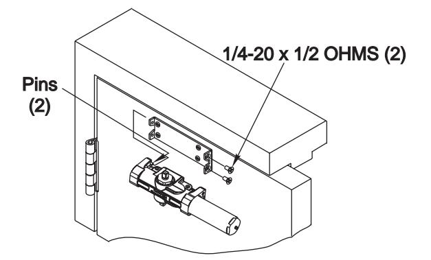
2. Install Closer Bracket 3. Mount Closer Body to Closer Bracket
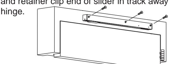
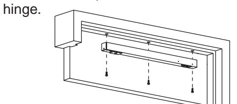
4. Attach Track to Door
Fasten track assembly to door with spring buffer toward hinge edge of door, open side facing up, and retainer clip end of slider in track away from hinge.
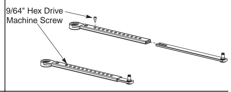
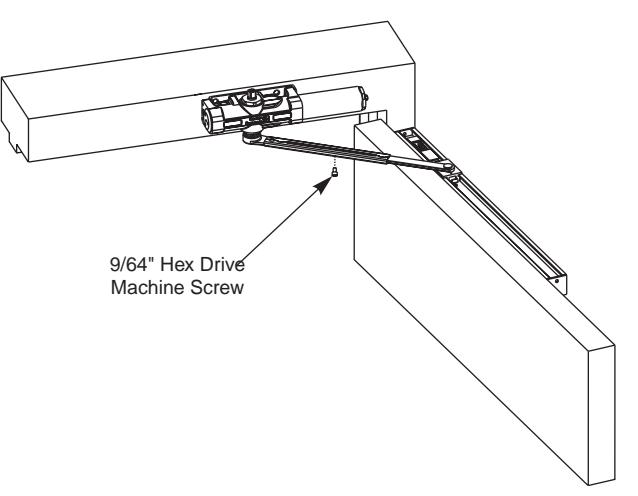
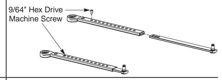
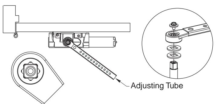
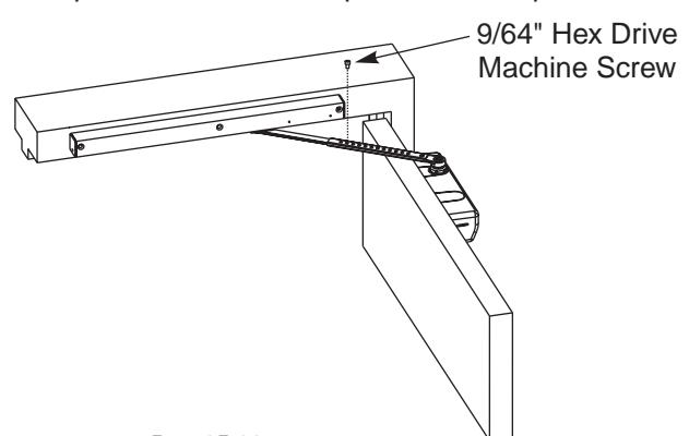
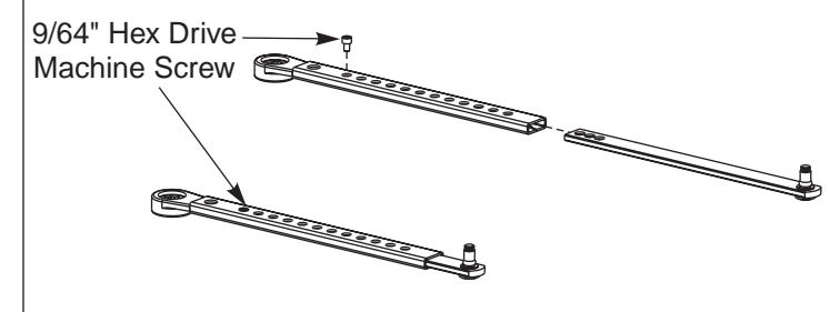
5. Adjust Arm to Shortest Length
Install 9/64" hex drive socket head screw from screw pack to the arm's shortest length as shown below.
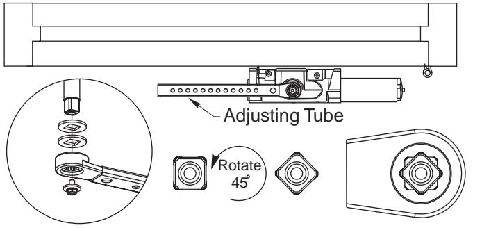
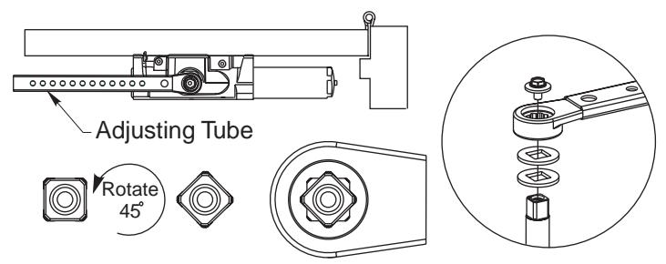
6. Place Slide Arm on Pinion Shaft
Place the two washers and slide arm on the pinion shaft, indexed as shown below. Secure the arm with the arm screw and washer as indicated.
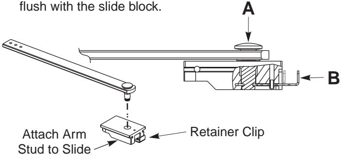
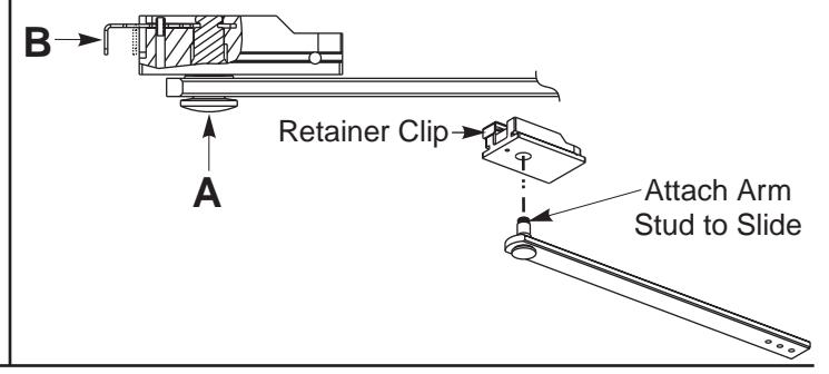
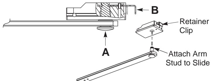
7. Insert Arm Stud into Slide Block
A) Insert the arm stud into the slide block in the track assembly. B) Secure by pushing in on the retainer clip that extends from the slide block in the track, until it is flush with the slide block.
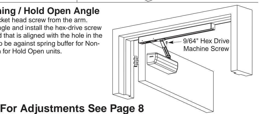
8. Adjusting Door Opening / Hold Open Angle
Remove the 9/64" hex drive socket head screw from the arm. Open the door to the desired angle and install the hex-drive screw into the hole in the adjusting rod that is aligned with the hole in the adjusting tube. Slider to be against spring buffer for Non-Hold Open units or in hold open for Hold Open units. NOTE:
For Adjustments See Page 8
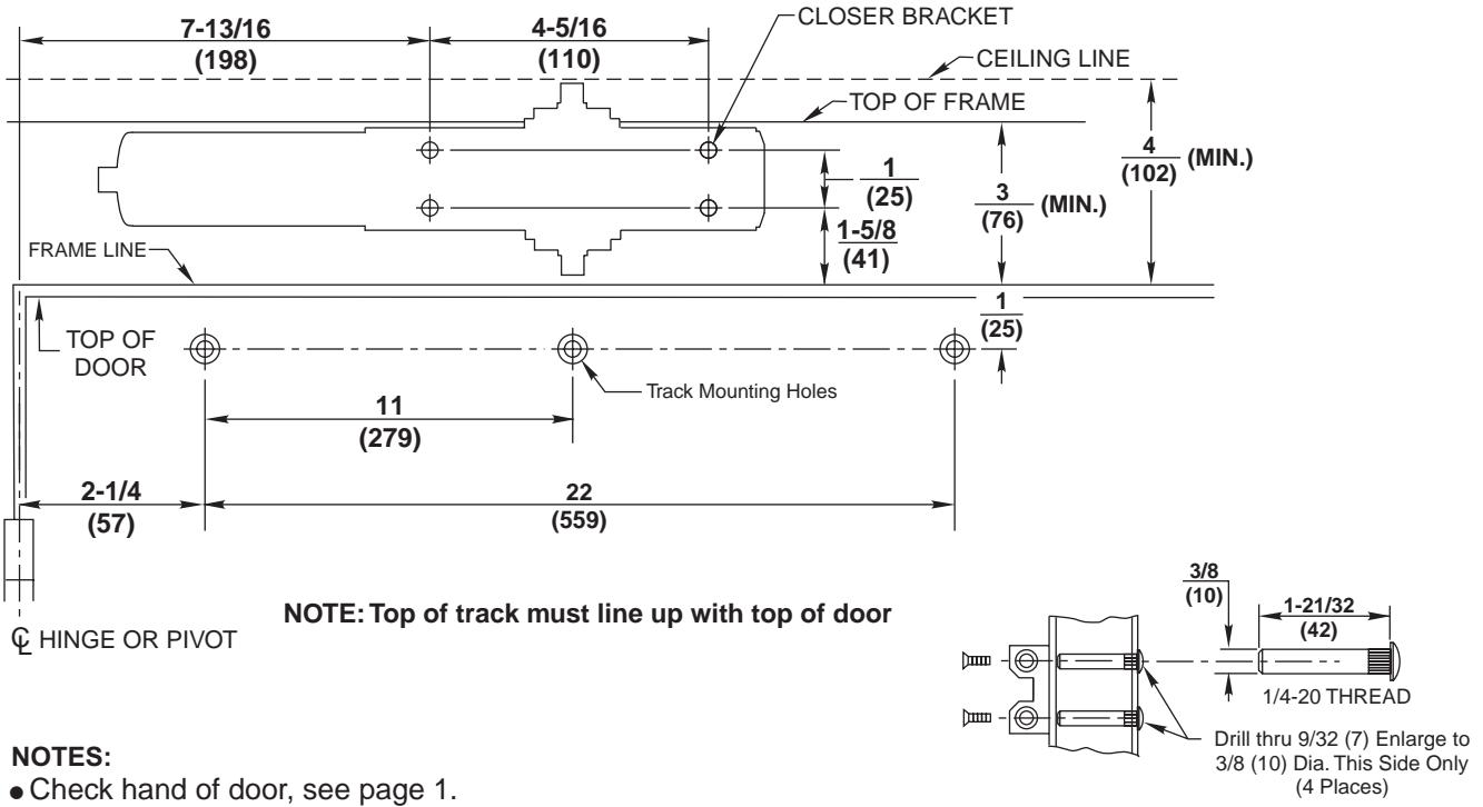
Pull Side, Door Mounted Closer Application DC6230 & DC6430 Series
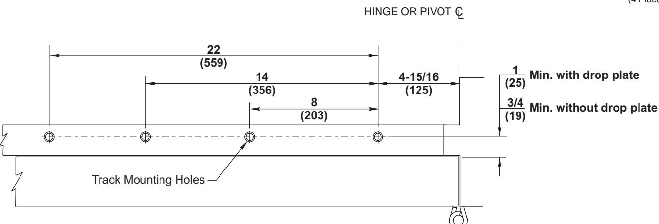
1. Template
Mark Door and Jamb (for closer bracket and track)
- Door will travel additional 5° to dead stop.
- Door hold open position adjustable from 85° to 110° of door opening.
C HINGE OR PIVOT
NOTES:
- Check hand of door, see page 1.
- Right Hand Application Shown. Left Hand Opposite.
- Dimensions given in inches (mm). Do Not Scale Drawing.
- Closer must be installed in a true horizontal plane to ensure proper closer performance.
- Door opening (up to 110°) is dependent upon door, frame, wall and hinge/pivot conditions permitting.
- Door closer with cover has a projection of 2-3/4 (70) from door.
- Minimum ceiling clearance from frame rabbet: 2-1/16 (52).
- Maximum 1/8 (3) hinge side frame reveal.
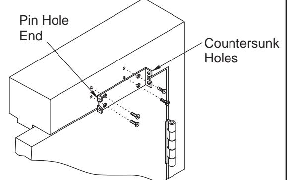
Pull Side, Door Mounted Closer Application (Continued)
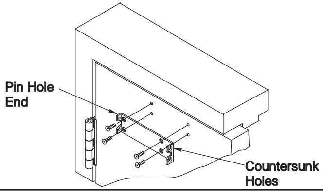
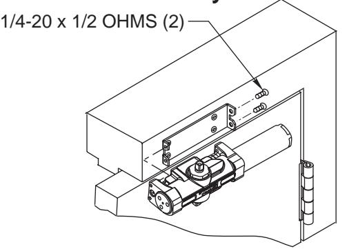
2. Install Closer Bracket 3. Mount Closer Body to Closer Bracket
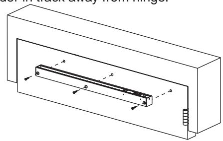
4. Attach Track to Frame
F ith spring buffer toward hinge edge of frame, open side facing down, and retainer clip end of slider in track away from asten track assembly to frame w
5. Adjust Arm to Shortest Length
Install 9/64" hex drive socket head screw from screw pack to the arm's shortest length as shown below.
6. Place Slide Arm on Pinion Shaft
Place the two washers and slide arm on the pinion shaft, indexed as shown below. Secure the arm with the arm screw and washer as indicated.
7. Insert Arm Stud into Slide Block
A) Insert the arm stud into the slide block in the track assembly. B) Secure by pushing in on the retainer clip that extends from the slide block in the track, until it is flush with the slide block.
8. Adjusting Door Opening / Hold Open Angle
Remove the 9/64" hex drive socket head screw from the arm. Open the door to the desired angle and install the hex-drive screw into the hole in the adjusting rod that is aligned with the hole in the adjusting tube. Slider to be against spring buffer for Non-Hold Open units or in hold open for Hold Open units. NOTE:
For Adjustments See Page 8
Page 5 80-9360-6009-152 Rev. 05-08
Push Side Application DC6240 & DC6440 Series
1. Template
FRAME LINE
DOOR STOP
188F68 / 597F58 DROP PLATE
OR
CLOSER BRACKE
(25)
Mark Door and Stop (for closer bracket or drop plate and track)
4-3/4
(121)
(76)
<u>3-3/16</u>
(81)
(38)
1-3/16
(30)
(178)
- Door will travel additional 5° to dead stop.
- Door hold open position adjustable from 70° to 105° of door opening.
(76)
3/8
(10)
MOUNTING SCREW SPECIFICATIONS ARM AND CLOSER BRACKET
1/4-20 oval head machine screw or 1/4-14 self-drilling screw Type BSD. 3/16 (5) diameter pilot hole required for Wood Applications.
- or -
Option M54: Sex nuts, furnished when ordered
NOTES:
- Check hand of door, see page 1.
- Right Hand Application Shown. Left Hand Opposite.
- Dimensions given in inches (mm). Do Not Scale Drawing.
- Closer must be installed in a true horizontal plane to ensure proper closer performance.
4-5/16
(110)
- 110° Maximum door opening, depending upon door, frame, wall, and hinge / pivot conditions.
- 105° Hold Open position (A1).
- Minimum stop width: 1-1/2 (38), 1-3/4 (45) with drop plate.
- Minimum top rail: 5-1/8 (130), 2-9/16 (65) with drop plate.
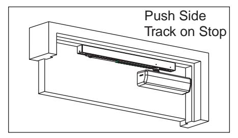
Push Side,Track on Stop Application (Continued)
2. Install Closer Bracket to Door
or, if required, drop plate to door and then closer bracket to drop plate.
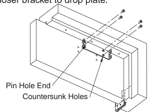
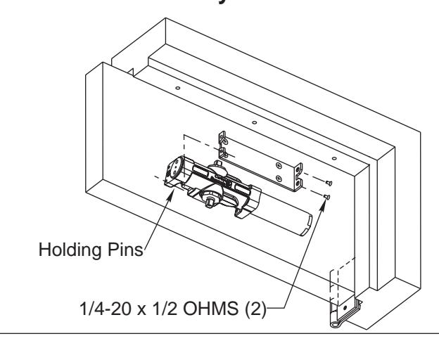
3. Mount Closer Body to Closer Bracket
4. Attach Track to Frame
F ith spring buffer toward hinge edge of door, open side facing down, and retainer clip end of slider in track away from asten track assembly to frame w
5. Adjust Arm to Shortest Length
Install 9/64" hex drive socket head screw from screw pack to the arm's shortest length as shown below.
6. Place Slide Arm on Pinion Shaft
Place the two washers and slide arm on the pinion shaft, indexed as shown below. Secure the arm with the arm screw and washer as indicated.
7. Insert Arm Stud into Slide Block
A) Insert the arm stud into the slide block in the track assembly. B) Secure by pushing in on the retainer clip that extends from the slide block in the track, until it is flush with the slide block.
8. Adjusting Door Opening / Hold Open Angle
Remove the 9/64" hex drive socket head screw from the arm. Open the door to the desired angle and install the hex-drive screw into the hole in the adjusting rod that is aligned with the hole in the adjusting tube. Slider to be against spring buffer for Non-Hold Open units or in hold open for Hold Open units. NOTE:
Spring Power Adjustment
Locate spring power adjuster from Illustration below DC6400 Half Size Adjustment as Desired DC6200 Size 1 thru 6 Adjustment See Chart
DC6200 SPRING POWER ADJUSTMENT CHART
- All DC6200 closers are factory set at an approximate Size 3.
- Adjust closer as necessary for door size using this chart.
- Readjustment may be required to suit prevailing conditions.
| Size of D | No. of Full | Equivalent | |||
|---|---|---|---|---|---|
| Interior |
Exterior
In Swing |
Exterior
Out Swing |
(360°) Turns
Clockwise of Power Adjuster |
Closer Size
(Approx.) |
|
| 2' 4" (712) | 2'6" (764) | 4 | 2 | ||
| 2'6" (764) | 3'0" (915) | 8 | 3 | ||
| 3 0" (915) | 3'6" (1067) | 2'6" (764) | 12 | 4 | |
| 3 6 (1067) | 4'0" (1219) | 3'0" (915) | 16 | 5 | |
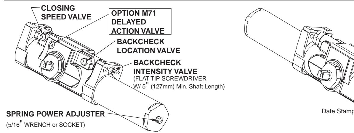
Closing Speed Valve (3/32 Allen Wrench Provided)
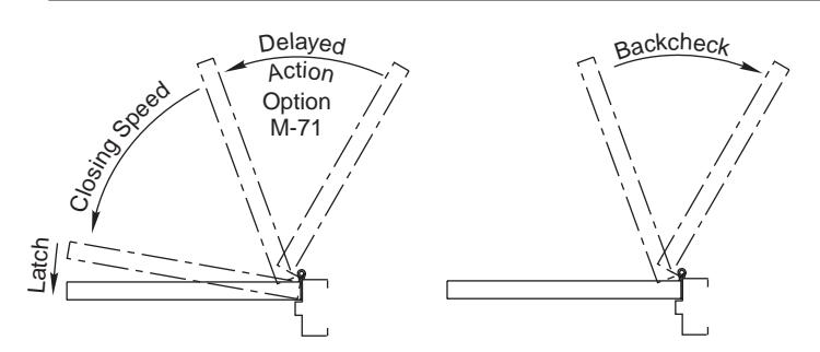
To adjust speed of door closing from fully open to a position 2" to 5" from closed, turn Closing Speed Valve CLOCKWISE to SLOW closing, COUNTER-CLOCKWISE to SPEED closing.
Latching Speed Valve (3/32 Allen Wrench Provided)
After closing speed has been obtained, turn latching speed valve CLOCKWISE to SLOW latching or COUNTER-CLOCKWISE to SPEED latching for last 2" to 5" of door travel.
NOTE: Set combination of CLOSING and LATCHING speeds to between 3 and 7 seconds. Use of door by handicapped, elderly or small children may require even greater closing time.
Optional Delayed Action Valve (3/32 Allen Wrench Provided) Turn valve CLOCKWISE to SLOW closing, COUNTER-CLOCKWISE to SPEED closing. Delayed action may be adjusted from 20 seconds to 90 seconds, depending on degree of door swing. Delay occurs at the beginning of the door closing cycle from fully open down to 70°, where the closing speed valve then begins its control.
Backcheck Location Valve (3/32 Allen Wrench Provided)
Valve is closed, as shipped, from factory. To increase the degree of door opening where backcheck takes effect, turn valve counter-clockwise.
| VALVE | Door Position | |
|---|---|---|
| CLOSED | 60°-65° | |
| OPEN | 85°-90° | |
Degrees shown are approximate
Backcheck Intensity Valve
Turn valve COUNTER-CLOCKWISE to reduce backcheck or CLOCKWISE to increase backcheck. (Backcheck should be set to give a soft cushioning action, not a sudden stop.)
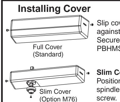
Slip cover over closer. Hold tightly against closer mounting surface. Secure on each side with 6-32 x 1/4" PBHMS screws.
LATCHING :
Power Size Stamp
SPEED
VALVE
Slim Cover Option M76 only Position spindle cap over unused spindle and secure with truss head screw.
Copyright © 2007 Corbin Russwin, Inc. All rights reserved. Reproduction in whole or in part without the express written permission of Corbin Russwin Inc. is prohibited.

www.corbinrusswin.com
Corbin Russwin Architectural Hardware 1902 Airport Road Monroe, NC 28110 800-543-3658