Corbin Russwin DC6210 and DC6410 Series Heavy Duty Parallel Installation Instructions_80-9360-6002-152
Open the original PDF document
View PDF
Installation Instructions

ASSA ABLOY
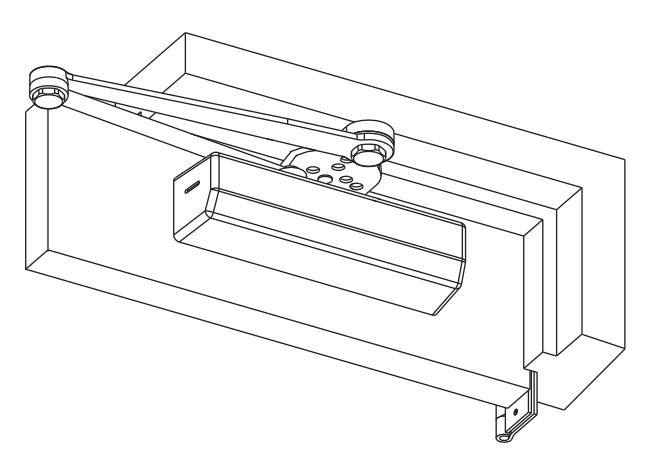
Universal Door Closers with A3 Heavy Duty Non-Hold Open Parallel Arm
DC6210 Series Multi-Sized 1 thru 6
DC6410 Series Half-Size 1 thru 6
Heavy Duty Non-Hold Open
IMPORTANT:
- An improperly installed or incorrectly adjusted door closer may cause property damage or personal injury; and will void product warranty.
- To avoid personal injury, DO NOT DISASSEMBLE THIS DOOR CLOSER BODY .
- Door closers must be securely fastened to a properly reinforced door and frame with fasteners provided.
- An auxiliary door stop, BY OTHERS, is required for this Installation.
BEFORE INSTALLING:
- The Americans with Disabilities Act (ADA) requires that doors having door closers have an opening force not to exceed 5 lbf.
- The door closer's power size adjustment feature may require adjustment to its lowest setting to comply with ADA opening force guidelines.
- ADA compliant closers are: DC6210 & DC6411.
| Size of Door & Door Closer | |||||
|---|---|---|---|---|---|
|
Type
of Installation |
Interior |
Exterior
In-swinging |
Exterior
Out -swinging |
Recommended
Closer Size |
**Max.
Opening Force Ibs/f |
|
2'4"
2'6" |
1 2 |
8
14 |
|||
| Parallel | 3'0" | 2'6" | 3 | 16 | |
| Arm | 3'6" |
3'0"
*3'6" |
4 | 22 | |
|
4'0"
4'6" |
*4'0" | 6 |
24
26 |
||
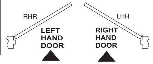
TO DETERMINE HAND OF YOUR DOOR:
*DC6410 Series Recommended
** NOTE: These forces are for standard templating with bearing type hinges and do not account for pressure differentials and draft. Half size closers DC6410 are capable of being adjusted to next higher setting.
Installation Instructions
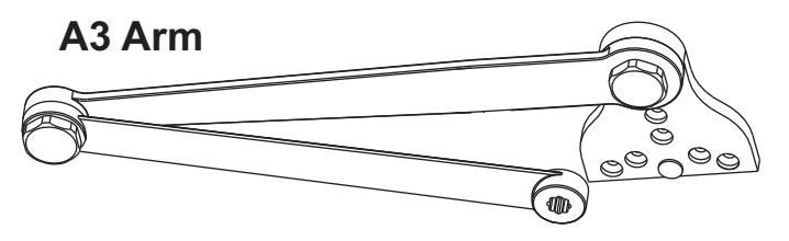
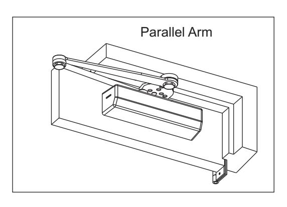
Parallel Arm Application DC6210 / DC6410 Series x A3 Arm Option.
1. Template
Mark Door and Jamb (for closer bracket and arm bracket) Use template and dimensions charted.
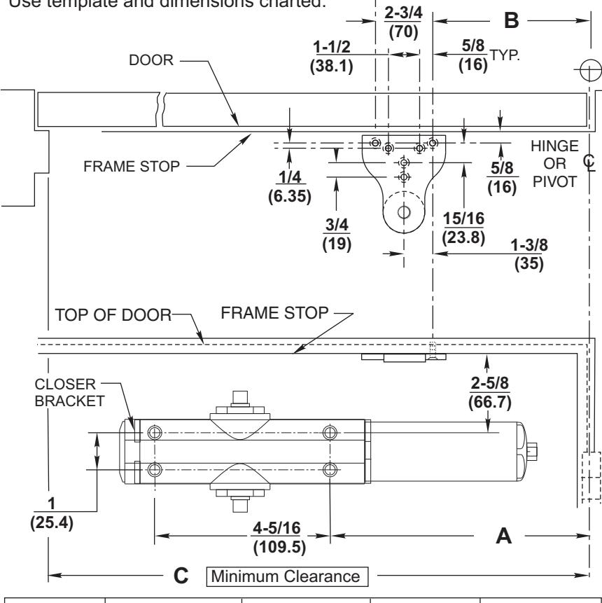
|
MAXIMUM
OPENING |
А | В | С | Application |
|---|---|---|---|---|
| 90° |
12-3/4
(324 mm) |
11-5/8
(295 mm) |
27-3/4"
(705 mm) |
NON
A.D.A. |
| 180° |
8-11/16
(221 mm) |
7-9/16
(192 mm) |
23-5/8"
(600 mm) |
E |
NOTES:
- Check hand of door, see page 1.
- Right Hand Application Shown. Left Hand Opposite.
- Dimensions given in inches (mm). Do Not Scale Drawing.
- Closer must be installed in a true horizontal plane to ensure proper closer performance.
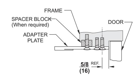
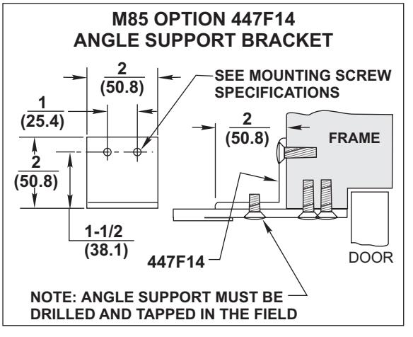
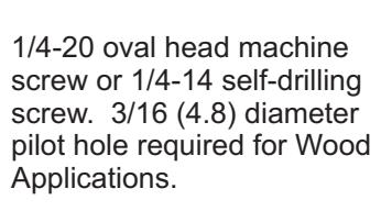
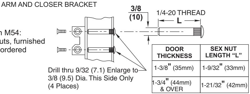
MOUNTING SCREW SPECIFICATIONS
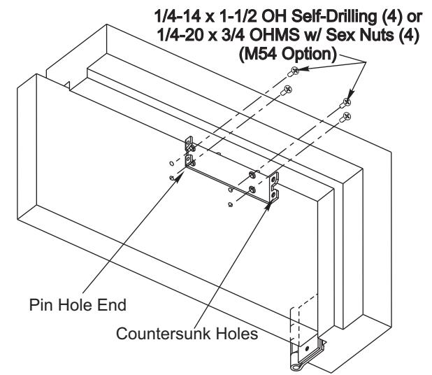
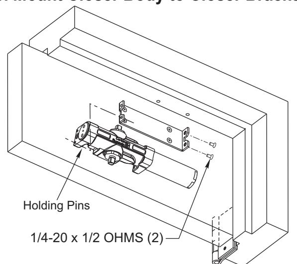
2. Install Closer Bracket 3. Mount Closer Body to Closer Bracket
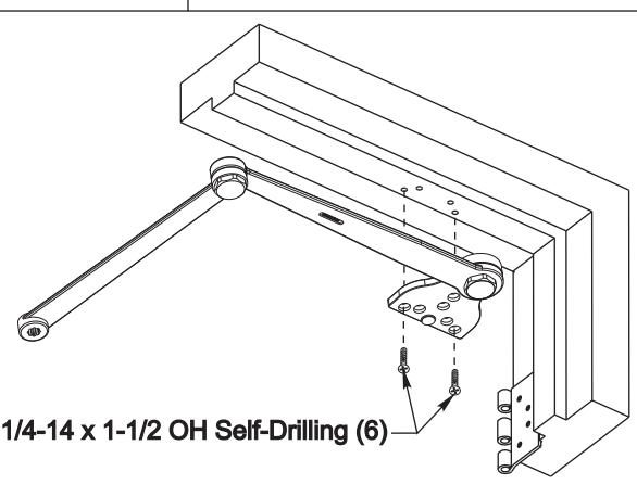
4. Mount Arm to Door Frame
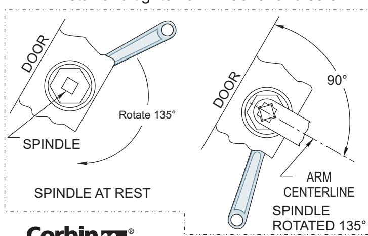
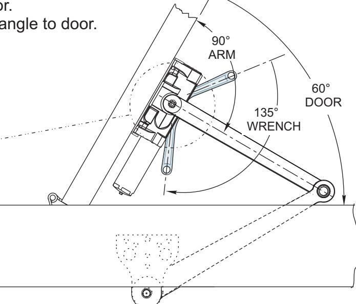
5. Connect Arm To Closer
Using hex wrench provided close, (turn clockwise) CLOSING SPEED VALVE (see page 4 for location on closer). DO NOT OVER TIGHTEN.
Open door to approximately 60°
Using wrench on underside of spindle, rotate spindle approximately 135° toward hinge edge of door.
Install arm on spindle at an approximate 90° angle to door.
Reopen CLOSING SPEED VALVE.
Install and tighten arm washer and screw

ASSA ABLOY
ALL ANGLES SHOWN ARE APPROXIMATE
Spring Power Adjustment
Locate spring power adjuster from Illustration below DC6400 Half Size Adjustment as Desired DC6200 Size 1 thru 6 Adjustment See Chart
DC6200 SPRING POWER ADJUSTMENT CHART
- All DC6200 closers are factory set at an approximate Size 3.
- Adjust closer as necessary for door size using this chart.
- Readjustment may be required to suit prevailing conditions.
| Size of Do | No. of Full | Equivalent | |||
|---|---|---|---|---|---|
| Interior |
Exterior
In Swing |
Exterior
Out Swing |
(360°) Turns
Clockwise of Power Adjuster |
Closer Size
(Approx.) |
|
| 2 ' 4" (712) | 2 ' 6" (764) | 4 | 2 | ||
| 2 ' 6" (764) | 3 ' 0" (915) | 8 | 3 | ||
| 3 ' 0" (915) | 3 ' 6" (1067) | 2'6" (764) | 12 | 4 | |
| 3 ' 6" (1067) | 4 ' 0" (1219) | 3'0" (915) | 16 | 5 | |
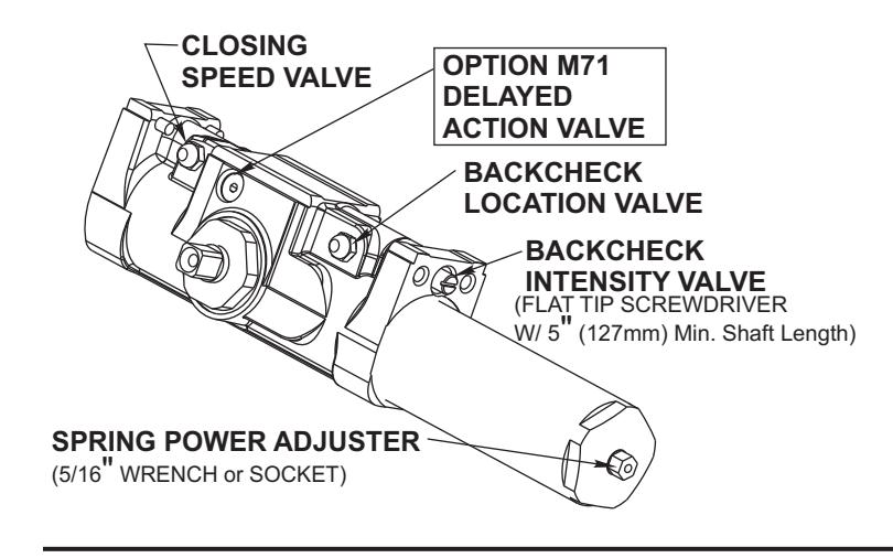
Closing Speed Valve (3/32 Allen Wrench Provided)
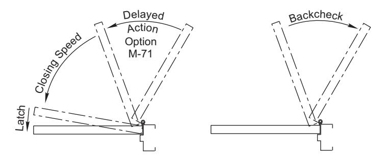
To adjust speed of door closing from fully open to a position 2" to 5" from closed, turn Closing Speed Valve CLOCKWISE to SLOW closing, COUNTER-CLOCKWISE to SPEED closing.
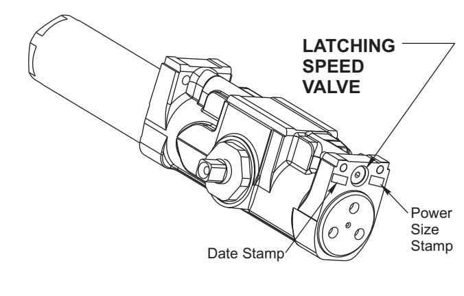
Latching Speed Valve (3/32 Allen Wrench Provided)
After closing speed has been obtained, turn latching speed valve CLOCKWISE to SLOW latching or COUNTER-CLOCKWISE to SPEED latching for last 2" to 5" of door travel.
NOTE: Set combination of CLOSING and LATCHING speeds to between 3 and 7 seconds Use of door by handicapped, elderly or small children may require even greater closing time.
Delayed Action Valve (3/32 Allen Wrench Provided)
Turn valve CLOCKWISE to SLOW closing, COUNTER-CLOCKWISE to SPEED closing. Delayed action may be adjusted from 20 seconds to 90 seconds, depending on degree of door swing. Delay occurs at the beginning of the door closing cycle from fully open down to 70°, where the closing speed valve then begins its control.
Backcheck Location Valve (3/32 Allen Wrench Provided)
Valve is closed, as shipped, from factory. To increase the degree of door opening where backcheck takes effect, turn valve counter-clockwise.
| VALVE | OCCURS AT |
|---|---|
| CLOSED | 65°-70° |
| OPEN | 95°-100° |
Degrees shown are approximate
Backcheck Intensity Valve
Turn valve COUNTER-CLOCKWISE to reduce backcheck or CLOCKWISE to increase backcheck. (Backcheck should be set to give a soft cushioning action, not a sudden stop).
Installing Cover
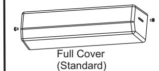
Slip cover over closer. Hold tightly against closer mounting surface. Secure on each side with 6-32 x 1/4" PBHMS screws.
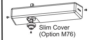
Slim Cover Option M76 only Position spindle cap over unused spindle and secure with a 10-32 x 3/8 PTHMS screw.

ASSA ABLOY
Copyright© 2004, 2010 Corbin Russwin, Inc., an ASSA ABLOY Group company. All rights reserved. Reproduction in whole or in part without the express written permission of Corbin Russwin, Inc. is prohibited