Corbin Russwin DC6000 Series Door Closer, DC6200, DC6400 A10 Option HD Parallel Arm Installation Instructions_80-9360-6004-152
Open the original PDF document
View PDFInstallation Instructions
DC6200 Series Multi-Sized 1 thru 6
DC6400 Series Half-Sized 1 thru 6
Corbin
Universal Door Closers Non-Hold Open with A10 Heavy Duty Arm
IMPORTANT:
- An improperly installed or incorrectly adjusted door closer may cause property damage or personal injury; and will void product warranty.
- To avoid personal injury, DO NOT DISASSEMBLE THIS DOOR CLOSER BODY .
- Door closers must be securely fastened to a properly reinforced door and frame with fasteners provided.
BEFORE INSTALLING:
-
The Americans with Disabilities Act (ADA) requires that doors having door closers have an opening force not to exceed 5 lbf.
Use standard templating for regular arm and parallel arm applications. Jamb
- Use standard templating for regular arm and parallel arm applications. Jamb mounted applications use the template for 140° door opening to achieve the required opening force.
- The door closer's power size adjustment feature may require adjustment to its lowest setting to comply with ADA opening force guidelines.
- ADA compliant closers are: DC6200 & DC6401.
| Size of Door & Door Closer | ||||||
|---|---|---|---|---|---|---|
|
Type
of Installation |
Interior |
Exterior
In-swinging |
Recommended
Closer Size |
**Max.
Opening Force Ibs/f |
||
|
Regular
Arm |
2'4"
3'0" 3'6" 4'0" 4'6" 5'0" |
2'6"
3'0" 3'6" *4'0" |
1
2 3 4 5 |
8
14 16 22 24 26 |
||
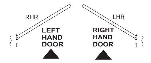
TO DETERMINE HAND OF YOUR DOOR:
*DC6400 Series Recommended
** NOTE: These forces are for standard templating with bearing type hinges and do not account for pressure differentials and draft. Half size closers DC6400 are capable of being adjusted to next higher setting.
Installation Instructions
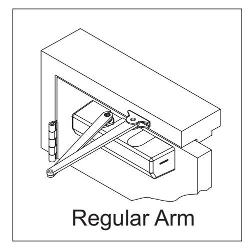
Regular Arm Application
DC6200 / DC6400 Series with A10 Heavy Duty Arm
Regular Arm
1. Template
Mark Door and Jamb (for closer bracket and arm bracket) For Vertical Dimensions use "Mounting Dimensions Chart"
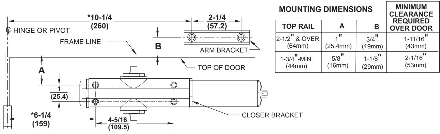
* To obtain extra closing force add 3" (77mm) to dimensions marked. This will limit degree of door opening to 110°.
NOTES:
- Check hand of door, see page 1.
- Right Hand Application Shown. Left Hand Opposite
- Dimensions given in inches (mm). Do Not Scale Drawing.
- Closer must be installed in a true horizontal plane to ensure proper closer performance.
- Door opening (up to 180°) is dependent upon door, frame, wall and hinge/pivot conditions permitting.
- Maximum Hinge Side Reveal 1/8" (3mm).

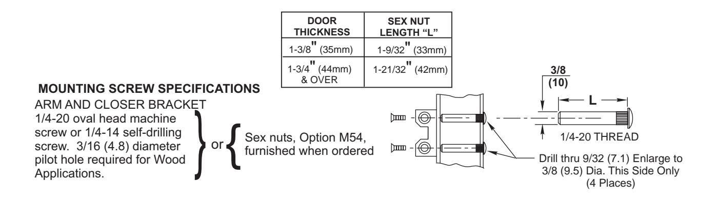
A10 Heavy Duty Arm (Continued)
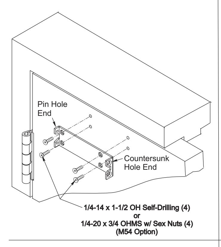
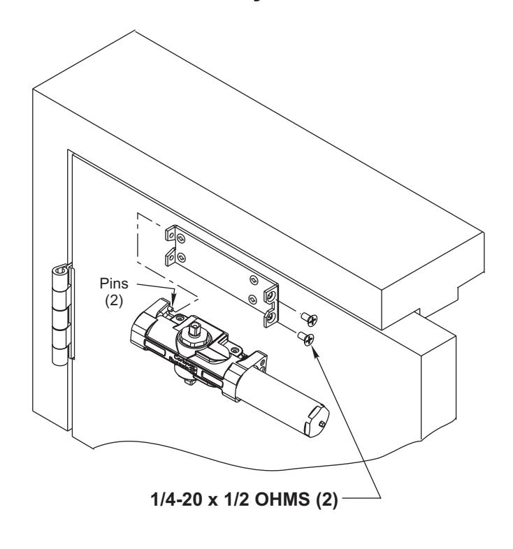
2. Install Closer Bracket 3. Mount Closer Body to Closer Bracket
Main arm projects straight out at 90° angle to door.
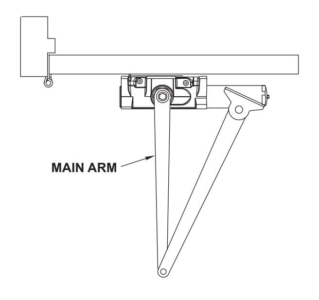
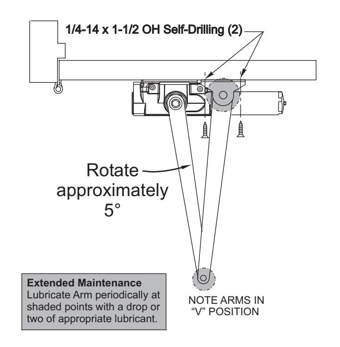
4. Position Arm on Closer 5. Preload and Fasten Arm to Frame
Close door, swing arms so that they form a "V" position. Align holes in arm bracket with pre-drilled holes on frame and install attaching screw.
Spring Power Adjustment
Locate spring power adjuster from Illustration below DC6400 Half Size Adjustment as Desired DC6200 Size 1 thru 6 Adjustment See Chart
DC6200 SPRING POWER ADJUSTMENT CHART
All DC6200 closers are factory set at an approximate Size 3.
- Adjust closer as necessary for door size using this chart.
- Readjustment may be required to suit prevailing conditions.
| Size of | Door | No. of Full | Equivalent |
|---|---|---|---|
| Interior |
Exterior
In Swing |
(360°) Turns
Clockwise of Power Adjuster |
Closer Size
(Approx.) |
| 2 ' 4 '' (712) | 2 ' 6 '' (764) | 4 | 2 |
| 2 ' 6 '' (764) | 3 ' 0" (915) | 8 | 3 |
| 3 ' 0 '' (915) | 3 ' 6" (1067) | 12 | 4 |
| 3 ' 6 '' (1067) | 4 ' 0" (1219) | 16 | 5 |
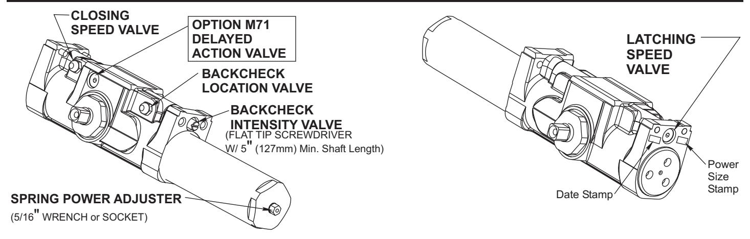
Closing Speed Valve (3/32 Allen Wrench Provided)
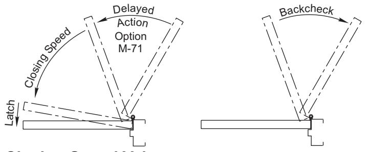
To adjust speed of door closing from fully open to a position 2" to 5" from closed, turn Closing Speed Valve CLOCKWISE to SLOW closing, COUNTER-CLOCKWISE to SPEED closing.
Latching Speed Valve (3/32 Allen Wrench Provided)
After closing speed has been obtained, turn latching speed valve CLOCKWISE to SLOW latching or COUNTER-CLOCKWISE to SPEED latching for last 2" to 5" of door travel.
NOTE: Set combination of CLOSING and LATCHING speeds to between 3 and 7 seconds Use of door by handicapped, elderly or small children may require even greater closing time.
Delayed Action Valve (3/32 Allen Wrench Provided)
Turn valve CLOCKWISE to SLOW closing, COUNTER-CLOCKWISE to SPEED closing. Delayed action may be adjusted from 20 seconds to 90 seconds, depending on degree of door swing. Delay occurs at the beginning of the door closing cycle from fully open down to 70°, where the closing speed valve then begins its control.
Backcheck Location Valve (3/32 Allen Wrench Provided)
Valve is closed, as shipped, from factory. To increase the degree of door opening where backcheck takes effect, turn valve counter-clockwise.
| VALVE | OCCURS AT | |
|---|---|---|
| CLOSED | 60°-65° | |
| OPEN | 85°-90° | |
Degrees shown are approximate
Backcheck Intensity Valve
Turn valve COUNTER-CLOCKWISE to reduce backcheck or CLOCKWISE to increase backcheck. (Backcheck should be set to give a soft cushioning action. Not a sudden stop).
Installing Cover
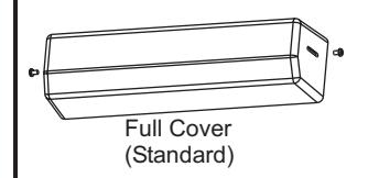
Slip cover over closer. Hold tightly against closer mounting surface. Secure on each side with 6-32 x 1/4" PBHMS screws.
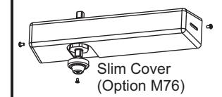
Slim Cover Option M76 only Position spindle cap over unused spindle and secure with 10-32 x 3/8 PTHMS screw.