Corbin Russwin DC3210 Series A2 A4 and A5 Option Installation Instructions
Open the original PDF document
View PDF

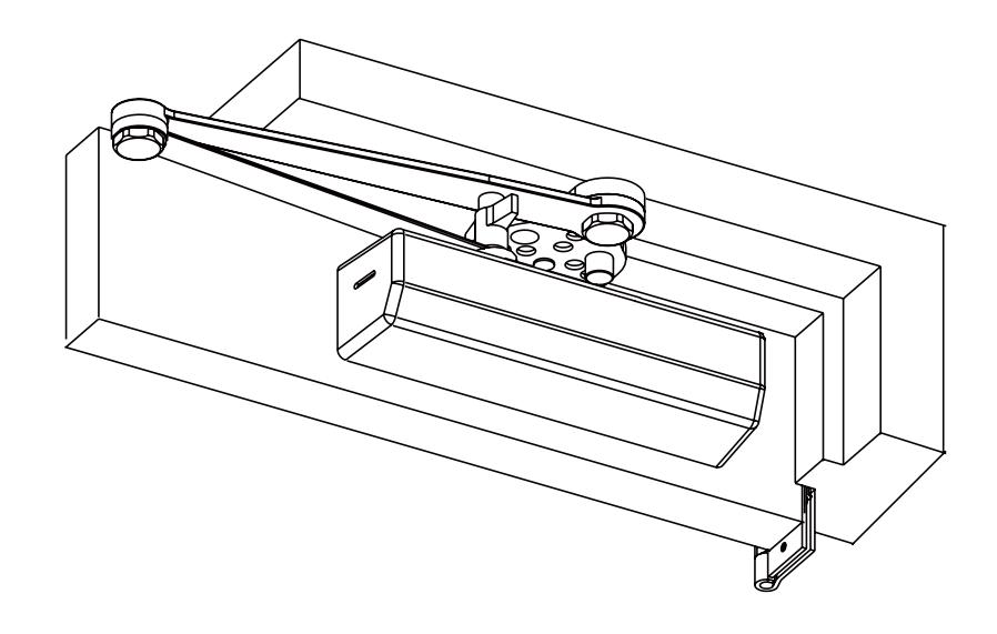
DC3210 Series
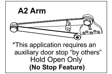
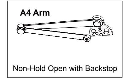
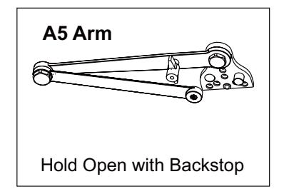
A2 Hold Open without Backstop A4 Non-Hold Open with Backstop A5 Hold Open with Backstop Heavy Duty Parallel Arm
Important
- An improperly installed or incorrectly adjusted door closer may cause property damage or personal injury; and will void product warranty.
- To avoid personal injury, DO NOT DISASSEMBLE THIS DOOR CLOSER BODY.
- Door closers must be securely fastened to a properly reinforced door and frame with fasteners provided.
- Door closers with a HOLD OPEN ARM are not permitted to be installed in fire door assemblies.
- Door and frame must be specifically templated for 85°, 90°, 95°, 100°, 105° orb 110° door swing.
A2, A4 or A5 Heavy Duty Parallel Arm
Installation Instructions

П
Introduction
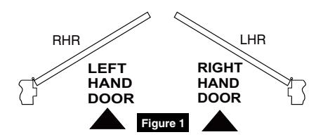
TO DETERMINE HAND OF YOUR DOOR:
| Size of Door & Door Closer | |||||||||
|---|---|---|---|---|---|---|---|---|---|
|
Type of
Installation |
Interior | Exterior Exterior In-swinging Out-swinging | Recommended Closer Size | **Max. Opening Force lbs/f | |||||
| Parallel Arm | 2' 4" | - | - | 1 | 8 | ||||
| 2' 6" | - | - | 2 | 14 | |||||
| 3' 0" | - | 2' 6" | 3 | 16 | |||||
| 3' 6" | - | 3' 0" | 4 | 22 | |||||
| 4' 0" | - | 3' 6" | 5 | 24 | |||||
| 4' 6" | - | 4' 0" | 6 | 26 | |||||
** NOTE: These forces are for standard templating with bearing type hinges and do not account for pressure differentials and draft.
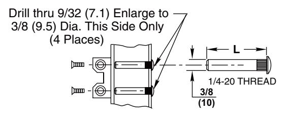
MOUNTING SCREW SPECIFICATIONS
ARM AND CLOSER BRACKET
1/4-20 oval head machine screw or 1/4-14 self-drilling screw Type BSD. 3/16 (4.8) diameter pilot hole required for Wood Applications.

|
DOOR
THICKNESS |
SEX NUT
LENGTH "L" |
|
|---|---|---|
| 1-3/8" (35mm) | 1-9/32" (33mm) | |
|
1-3/4" (44mm)
& OVER |
1-21/32" (42mm) | |
A2, A4 or A5 Heavy Duty Parallel Arm
Installation Instructions

ASSA ABLOY
2
Installation
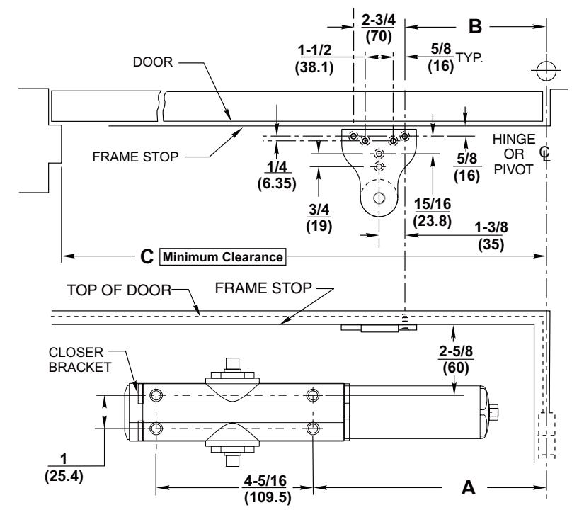
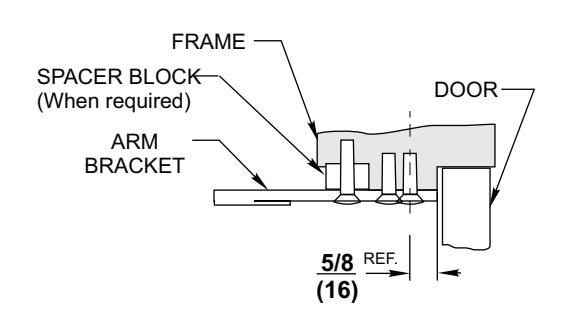
1. Template
Mark and prepare door and jamb (for closer bracket and arm bracket). Use template and dimensions charted. (Figure 2)
NOTES:
- Check hand of door. (Figure 1)
- Right Hand Application Shown, Left Hand Opposite
- Dimensions given in inches (mm). Do Not Scale Drawing.
- Closer must be installed in a true horizontal plane to ensure proper closer performance.
|
Opening
Maximum |
DIM. A | DIM. B |
DIM. C
Minimum |
|---|---|---|---|
| 85° | 13-3/4" | 12-9/16" | 28-3/4" |
| (349) | (319) | (730) | |
| 90° | 12-13/16" | 11-5/8" | 27-7/8" |
| (325) | (295) | (708) | |
| 100° | 11-1/4" | 10-1/16 | 26-1/4" |
| (286) | (256) | (667) | |
| 110° | 9-15/16" | 8-3/4" | 25" |
| (252) | (222) | (635) |
Figure 2
For installation assistance contact Corbin Russwin 1-800-543-3658 • techsupport.corbinrusswin@assaabloy.com
A2, A4 or A5 Heavy Duty Parallel Arm
Installation Instructions

2 Installation
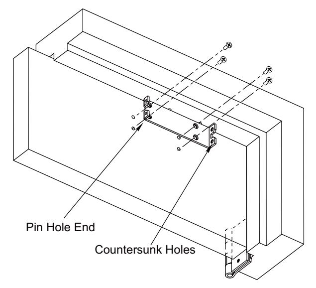
2. Install Closer Bracket. (Figure 3)
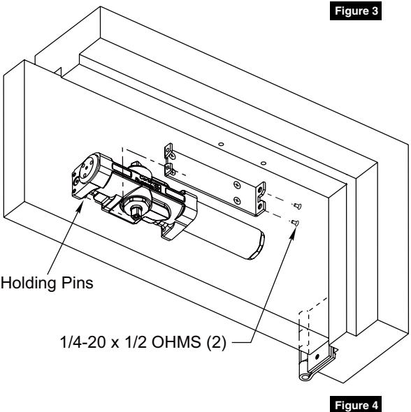
3. Mount Closer Body to Closer Bracket. (Figure 4)
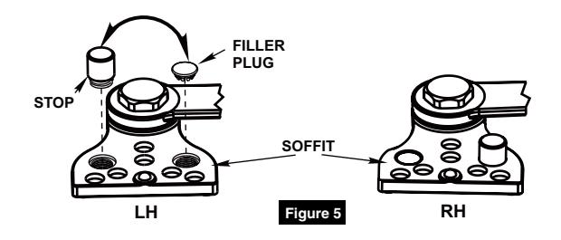
4. A4 & A5 Backstop Arms Only Arms shipped for Left Hand Door. To change handing: (Figure 5)
Remove Stop from Soffit with 5/32 Allen Wrench. Remove Filler Plug. Switch Stop and Filler Plug to opposite sides. Insert Stop and tighten. Push Filler Plug into hole.
A2, A4 or A5 Heavy Duty Parallel Arm
Installation Instructions

2 Installation
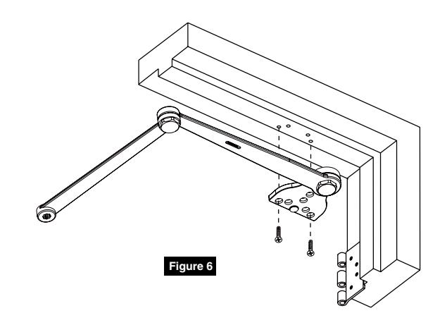
5. Mount Arm to Door Frame. (Figure 6)
6. Connect Arm To Closer. (Figure 7)
Using hex wrench provided, close (turn clockwise) CLOSING SPEED VALVE (see page 5 for location on closer). DO NOT OVER TIGHTEN.
- Open door to approximately 60°.
- Using wrench on underside of spindle, rotate spindle approximately 135° toward hinge edge of door.
- Install arm on spindle at an approximate 90° angle to door.
- Reopen CLOSING SPEED VALVE.
- Install and tighten arm washer and screw.
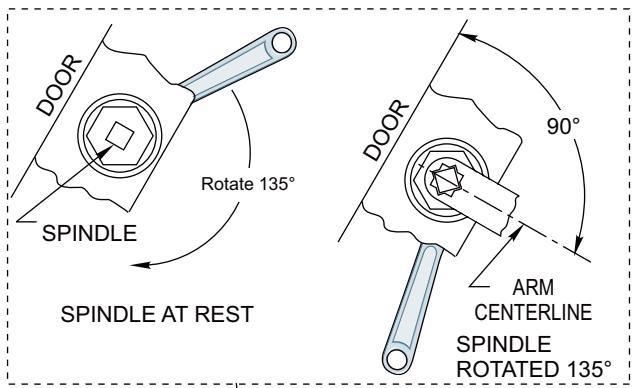
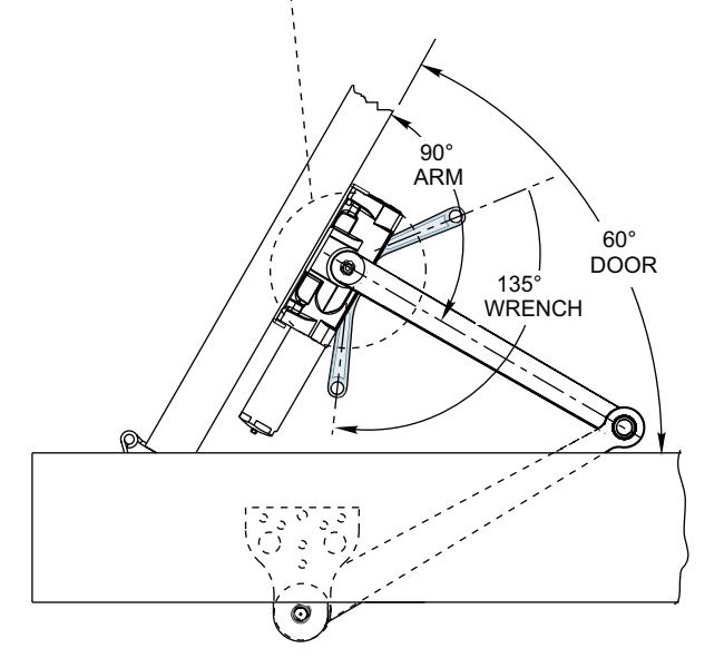
ALL ANGLES SHOWN ARE APPROXIMATE
Figure 7
A2, A4 or A5 Heavy Duty Parallel Arm
Installation Instructions

Figure 8
3 Adjustments
Adjustments (Figure 8)
(3/32 Allen Wrench Provided)
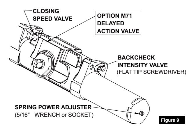
Closing Speed Valve (Figure 9)
To adjust speed of door closing from fully open to a position 2 to 5" from closed, turn Closing Speed Valve CLOCKWISE to SLOW closing, COUNTER-CLOCKWISE to SPEED closing.
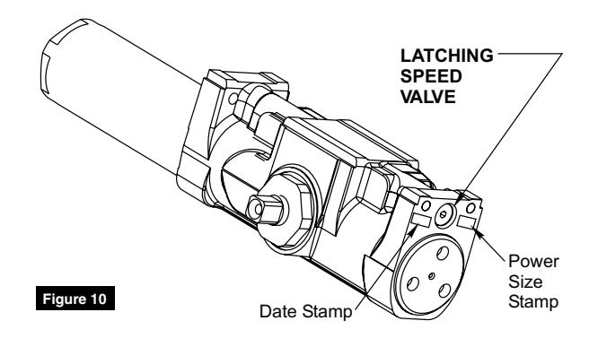
Latching Speed Valve (Figure 10)
After closing speed has been obtained, turn latching speed valve CLOCKWISE to SLOW latching or COUNTER-CLOCKWISE to SPEED latching for last 2" to 5" of door travel.
NOTE: Set combination of CLOSING and LATCHING speeds to between 3 and 7 seconds. Use of door by handicapped, elderly or small children, may require even greater closing time.
Backcheck Intensity Valve (Figure 9)
Turn valve COUNTER- CLOCKWISE to reduce backcheck or CLOCKWISE to increase backcheck. (Backcheck should be set to give a soft cushioning action, not a sudden stop).
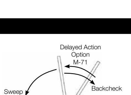
Delayed Action Valve (Figure 9)
Turn valve CLOCKWISE to SLOW closing, COUNTER-CLOCKWISE to SPEED closing. Delayed action may be adjusted from 20 seconds to 90 seconds, depending on degree of door swing. Delay occurs at the beginning of the door closing cycle from fully open down to 70°, where the closing speed valve then begins its control.
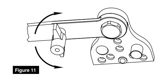
Hold Open Operation (Figure 11) (A2 and A5 Arms only)
A quarter turn of the tee handle in either direction engages or disengages the hold open feature.
Latch
A2, A4 or A5 Heavy Duty Parallel Arm
Installation Instructions

3
Adjustments
Adjust Spring Power According to Chart DC3200 Size 1-6 Adjustment (Figure 12)
- All DC3200 closers are factory set at an approximate Size 3.
- Adjust closer as necessary for door size using this chart.
- Readjustment may be required to suit prevailing conditions.
| Size of Door | No. of Full (360°) | Equivalent Claser | ||
|---|---|---|---|---|
| Interior |
Exterior
In-Swinging |
Exterior
Out-Swinging |
Turns Clockwise of
Power Adjuster |
Equivalent Closer
Size (Approx.) |
|
2' 4"
(712) |
2' 6"
(764) |
- | 4 | 2 |
|
2' 6"
(764) |
3' 0"
(915) |
- | 8 | 3 |
|
3' 0"
(915) |
3' 6"
(1067) |
2' 6"
(764) |
12 | 4 |
|
3' 6"
(1067) |
4' 0"
(1219) |
3' 0"
(915) |
16 | 5 |
Figure 12
4
Cover Installation
Install Cover (Figure 13)
Slip cover over closer. Hold tightly against closer mounting surface. Secure on each side with 6-32 x 1/4 PBHMS screws.
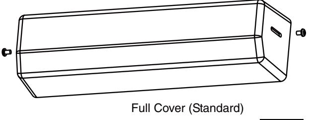
Figure 13
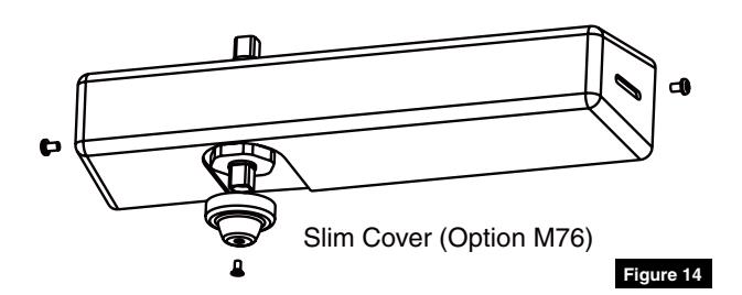
Slim Cover Option M76 only (Figure 14)
Position spindle cap over unused spindle and secure with truss head screw.

Corbin Russwin 225 Episcopal Road Berlin, CT 06037 Phone: 800-543-3658 Fax: 800-447-6714 corbinrusswin.com
Copyright © 2018 Corbin Russwin, Inc., an ASSA ABLOY Group company. All rights reserved. Reproduction in whole or in part without the express written permission of Corbin Russwin, Inc. is prohibited.