Corbin Russwin Cylindrical Deadbolts DL2200 DL3200 Series Installation Instructions
Open the original PDF document
View PDFInstallation Instructions

DL2200 and DL3200 Series
Cylindrical Deadbolts
ATTENTION INSTALLER
Installation of cylindrical deadbolts must be through bolted in all doors. If installation instructions are not followed, this may result in damage to the deadbolt and void the factory warranty.

For installation assistance contact Corbin Russwin
This product can expose you to lead which is known to the state of California to cause cancer and birth defects or other reproductive harm. For more information go to www.P65warnings.ca.gov.
Cylindrical Deadbolts
Installation Instructions

| TOC | Table of Contents | |
|---|---|---|
| 1 | Wood Door Preparation 3 | |
| a | Mark Door 3 | |
| b | Mortise and Drill Door 3 | |
| 2 | Frame Preparation 3 | |
| a | Mark Frame 3 | |
| b | Mortise and Drill Frame 4 | |
| 3 | DL2200 and DL3200 Deadbolt Installation 4 | |
| a | Install Deadbolt 5 | |
| b | Install Outside 5 | |
| c | Install Inside 5 | |
| d | Install Strike 5 | |
| 4 | IC Core Deadbolt Installation 6 | |
| a | Install Deadbolt 6 | |
| b | Install Outside 6 | |
| c | Install Inside 7 | |
| d | Install Strike 7 |
IMPORTANT:
The accuracy of the door preparation is critical for the proper functioning of this cylindrical deadbolt. Misalignment can cause premature wear and a lessening of security.
Cylindrical Deadbolts
Installation Instructions

1 Wood Door Preparation
a Mark Door
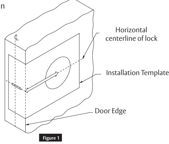
- a. Using a square, draw a horizontal line on the edge and inside surface of the door at the desired height above floor. 46" (117 m) high is recommended.
- b. Using the enclosed installation template, mark location of cross bore at proper backset. Mark edge of door for edge bore at proper centerline location. ( Figure 1)
b Mortise and Drill Door
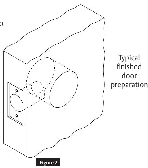
- a. Drill holes as directed on installation template. Drill 2-1/8" (54 mm) dia. cross bore first, (drill from both sides of door to avoid splintering the wood). Drill 1" (25 mm) dia. edge bore break through wall of 2-1/8" (54 mm) dia. cross bore.
- b. Insert deadbolt unit into hole in edge of door. Using the deadbolt front as a template, mark outline and location of two deadbolt screws. Remove deadbolt.
- c. Drill pilot holes for two attaching screws, and then mortise door edge 5/32" (4 mm) deep for deadbolt front. ( Figure 2 )
2 Frame Preparation
a Mark Frame
- a. Mark center location for strike on door frame at exactly the same height of the deadbolt's center on the door.
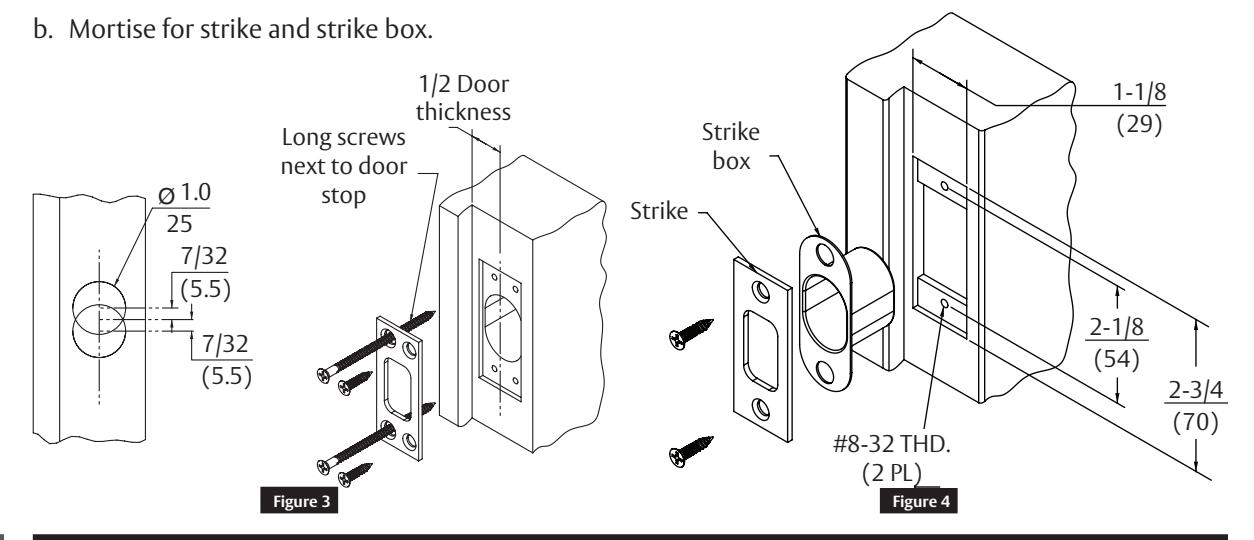
- b. To determine location of vertical centerline of strike, take half of door thickness (measured from doorstop or silencer). Place strike on door frame and center it on marks. Using the strike as template, mark the outline and locations of screw holes.
Cylindrical Deadbolts
Installation Instructions

2
Frame Preparation (cont.)
b
Mortise and Drill Frame
a. Drill two 1" (25 mm) dia. holes 7/32" (5.5 mm) above and below height line to a depth of 1-1/8" (29). Drill 1/8" (3 mm) dia. pilot holes for 3/4" (19) long screws and 5/32" (4 mm) dia. pilot holes for 3" (76 mm) long screws. (Figure 3)
3
DL2200 and DL3200 Deadbolt Installation
For IC Core Installation, skip to Section 4.
4
Cylindrical Deadbolts
Installation Instructions

3 DL2200 and DL3200 Deadbolt Installation (cont.)
a Install Deadbolt
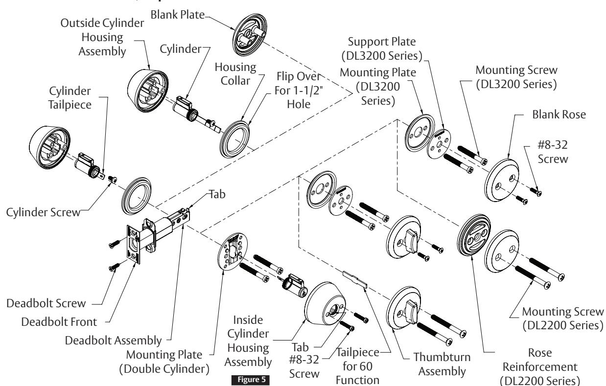
- a. Insert deadbolt unit into hole in door edge, making certain that tab on deadbolt is facing up as shown in Figure 5.
- b. Fasten deadbolt front and deadbolt assembly to door with two (2) deadbolt screws.
- c. Extend the deadbolt by turning the slot in the hub. Keep deadbolt extended during installation.
b Install Outside
- a. Insert cylinder into outside cylinder housing assembly and fasten it with cylinder screw.
- b. For 11-function, 13-function, and 17-function lock installation, shorten cylinder tailpiece if necessary by breaking it off at the score mark with pliers.
- c. Insert outside cylinder housing assembly though housing collar onto door with cylinder tailpiece going through slot in hub of deadbolt.
- d. Mount outside cylinder housing assembly (or outside blank plate) to door with two (2) 1/4-20 mounting screws and appropriate mounting plate.
c Install Inside
- a. For 12-function lock installation, insert cylinder with tailpiece going through slot in hub of deadbolt (flat side of cylinder, tailpieces meet within slot). For 60-function lock installation, insert tailpiece into the slot of hub of deadbolt.
- b. For 12-function lock installation, place inside cylinder housing assembly over the cylinder, making certain that tab is engaged in keyway slot. Insert key and turn until screw holes are exposed. For 13-function and 17-function lock installation, place thumbturn assembly onto tailpiece and align screw holes.
- c. For DL3200 series lock installation, use two (2) #8-32 screws to fasten inside cylinder housing assembly (or inside trim) to the assembly. For DL220 series lock installation, use two (2) 1/4-20 oval head screws.
- d. IMPORTANT: Operate deadbolt from both sides of door to check for proper operation. If binding occurs, recheck the door preparation and complete the installation procedure.
d Install Strike
a. Attach strike to door jamb as shown in Figures 3 and 4.
5
Installation Instructions

4 IC Core Deadbolt Installation
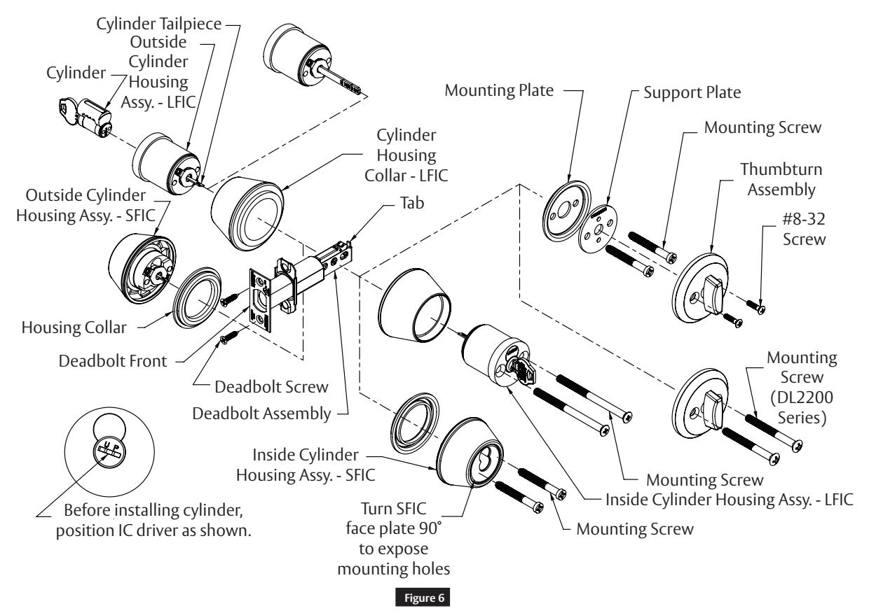
a Install Deadbolt
- a. Insert deadbolt unit into hole in door edge, making certain that tab on deadbolt is facing up as shown in Figure 6.
- b. Fasten deadbolt front and deadbolt assembly to door with two (2) deadbolt screws.
- c. Extend the deadbolt by turning the slot in the hub. Keep deadbolt extended during installation.
b Install Outside
- a. Position IC driver on cylinder housing as shown, install cylinder into cylinder housing assembly then remove the key from cylinder. If the plastic disposable temporary core is used, turn the plastic plug so that the slot is vertical.
- b. For 11-function, 13-function, and 17-function lock installation, shorten cylinder tailpiece if necessary by breaking it off at the score mark with pliers.
- c. Insert outside cylinder housing assembly though housing collar onto door with cylinder tailpiece going through slot in hub of deadbolt.
- d. Secure outside cylinder housing assembly mounting plate and support plate to door with two (2) 1/4-20 mounting screws if applicable.
Cylindrical Deadbolts
Installation Instructions

4 IC Core Deadbolt Installation (cont.)
c Install Inside
- a. For 12-function lock installation, insert cylinder housing assembly through cylinder housing collar and with tailpiece going through slot in hub of deadbolt (flat side of cylinder tailpieces meet within slot). For 13-function and17-function lock installation, place thumbturn assembly onto tailpiece.
- b. Align screw holes and fasten with two (2) 1/4-20 mounting screws (remove cylinder from inside SFIC cylinder housing assembly and turn face plate 90 ˚ to expose the mounting holes).
- c. IMPORTANT: Operate deadbolt from both sides of door to check for proper operation. If binding occurs, recheck the door preparation and complete the installation procedure.
d Install Strike
a. Attach strike to door jamb as shown in Figures 3 and 4.

Corbin Russwin, Inc. 225 Episcopal Road Berlin, CT 06037 USA Phone: 800-543-3658 Fax: 800-447-6714 www.corbinrusswin.com