Corbin Russwin CLX3300 Series Cylindrical Locks Installation Instructions_FM566
Open the original PDF document
View PDFInstallation Instructions Installation Instructions
CLX3300 Series Cylindrical Lockset
1 Tools Required
- #2 Phillips screwdriver
-
Lever release tool (provided)
5/16" drill bit
1/8" drill bit 5/32" drill bit
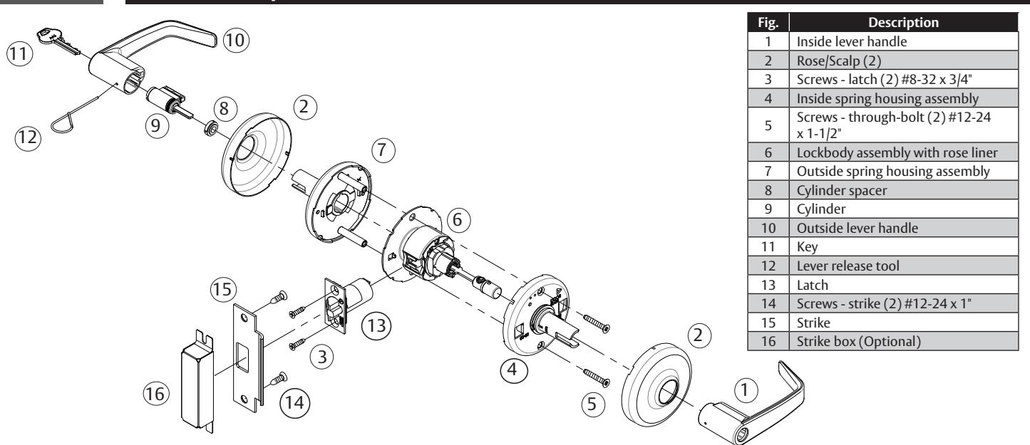
2 Product Components
3 Door Preparation
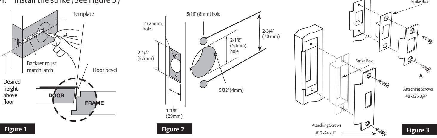
- 1. Use template FM567 to mark the door (See Figure 1).
- 2. Drill the door according to the template.
- 3. Verify the dimensions (See Figure 2).
- 4. Install the strike (See Figure 3)
IMPORTANT
- The accuracy of door preparation is critical for proper functioning and security of this lever handle lock. Misalignment can cause premature wear and a lessening of security.
- Be sure to verify backset before marking and drilling door.
For installation assistance contact Corbin Russwin:
1-800-543-3658 • techsupport.corbinrusswin@assaabloy.com •www.corbinrusswin.com.
Installation Instructions

4 Latch Installation
Insert latch in door. (Be sure bevel edge of bolt faces strike plate.) Attach with (2) #8-32 x 3/4" screws supplied.
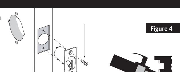
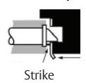
IMPORTANT: Deadlocking latch must stop on strike when door is closed.
5 Adjust Lock for Door Thickness (if necessary)
Lock is factory preset for 1-3/4" (44mm) doors unless specified. To adjust lock to door thickness if other than 1-3/4" (44mm):
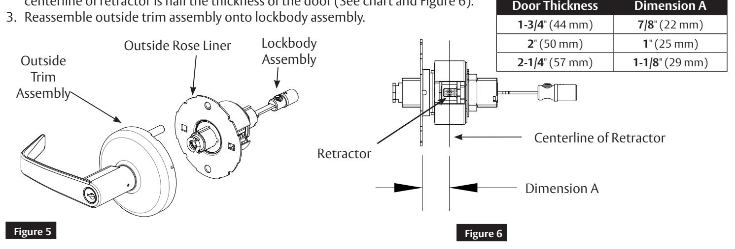
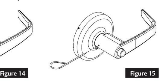
- 1. Remove outside trim assembly from the lockbody assembly. The lever, rose, and spring housing will remove as one piece from the lockbody (See Figure 5).
- 2. Rotate outside rose liner to adjust lock to fit door thickness, so distance (Dimension A) from inside surface of liner to centerline of retractor is half the thickness of the door (See chart and Figure 6).
6 Install Outside Assembly
To adjust lock to door thickness if other than 1-3/4" (44mm) refer to Section 5.
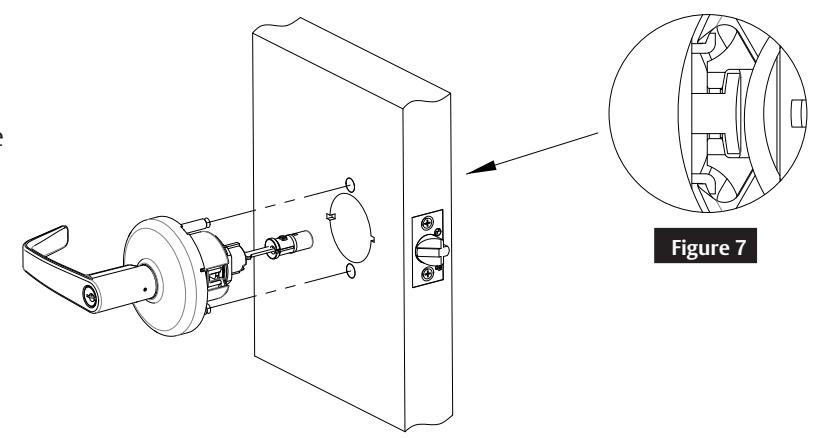
Insert outside trim assembly into door from outside making sure that lockbody hooks latch case and retractor engages bolt tail(s) (See Figure 7).
DO NOT FORCE. (If lockbody does not engage latch easily, check door preparation for errors.)
Latch bolt tail should be centered in depth of retractor. If it is not, refer to Section 5 to properly adjust the lock for door thickness.
Cylindrical Lockset
Installation Instructions

7 Install Inside Components
- 1. Remove rose from inside spring housing assembly.
- 2. Align and insert inside spring housing onto the installed lockbody.
- 3. Install screws to tighten the lock to the door.
- 4. Orient dimples on side of rose with openings on side of spring housing assembly (See Figure 8).
- 5. Install rose onto the inside spring housing assembly.
- 6. In the unlocked position, verify the button is adjusted properly. See Figure 9 for proper alignment. Adjust if necessary.
- 7. Install inside lever.
Note: Test for proper operation before closing door. Button in-line with shank
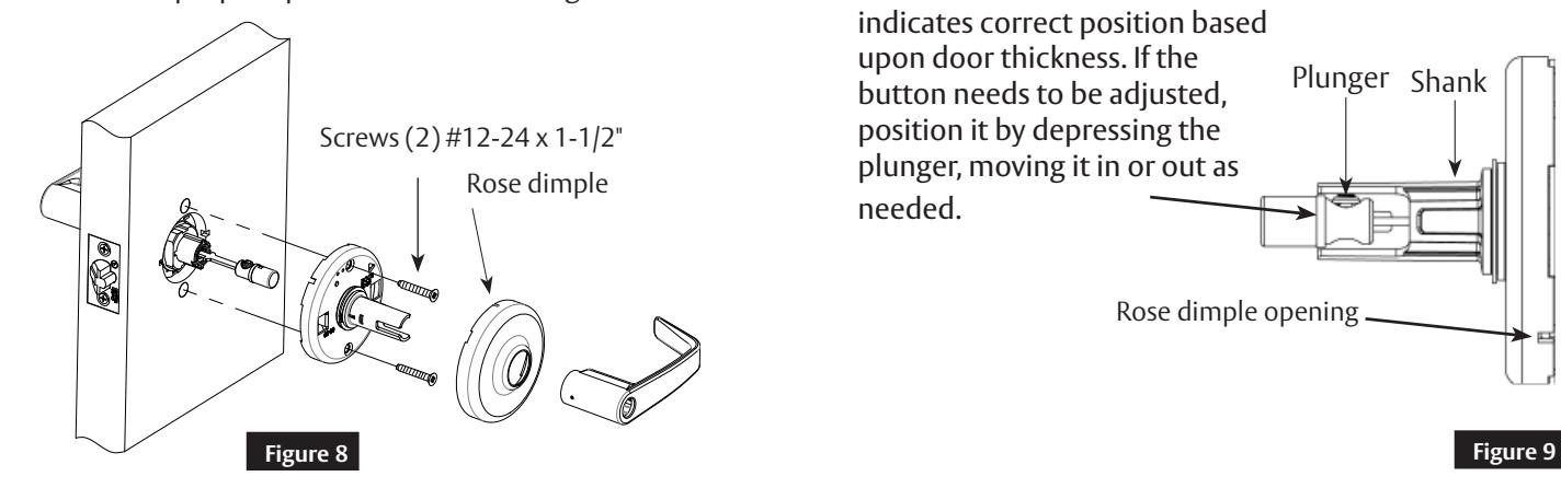
indicates correct position based upon door thickness. If the button needs to be adjusted, position it by depressing the plunger, moving it in or out as needed. Plunger Shank Rose dimple opening
8 Cylinder Installation
a Standard Cylinder (Figure 10)
IMPORTANT
Before installing cylinders:
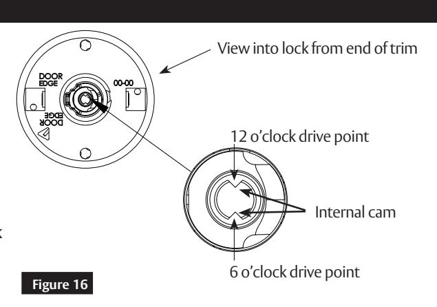
• Use a flat blade screwdriver to rotate cam until the driver points are in a 6 and 12 o'clock position (See Figure 16 on next page).
Verify that the cylinder spacer is already installed into the shank on the outside spring housing assembly. Cylinder spacer should be removed for 7-Pin cylinder. Note orientation of spacer, if it needs to be reinstalled.

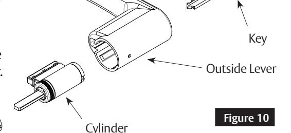

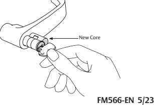
- Remove temporary construction core or plastic core. If keyed, use Control Key. Rotate 15° and pull.
- Insert permanent core into lever with control key. Rotate 15° and remove key.
Cylindrical Lockset
Installation Instructions

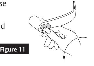
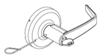
9 Lever Removal & Installation
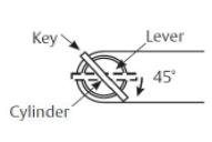
a Standard Cylinder (Figure 12)
Figure 12
To Remove:
Rotate key 45° and hold. Depress lever catch with lever release tool.
To Install:
With driver points at 6 and 12 (See Figure 16), rotate key 45° in either direction and slide lever on over the lever catch. Confirm the lever will not pull off.
b Interchangable or Removable Core (Figure 13)
To Remove:
Remove core and tailpiece, using key marked "control."
Insert slotted screwdriver or lever release tool into cylinder opening and make contact with lever catch.
Pull lever catch horizontally towards the opposite side of the cylinder opening and remove lever.
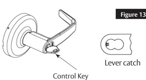
To Install:
Without the core installed, slide the lever on over the lever catch. Confirm the lever will not pull off. Install core and tailpiece, using key marked "control."
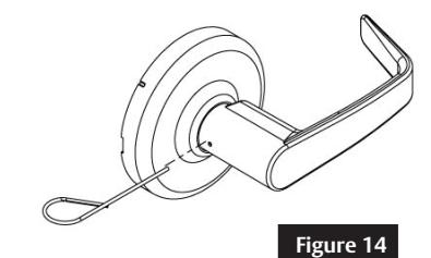
c Plain Lever (Figure 13) & Push/Turn Button (Figure 14)
To Remove:
Depress lever catch with lever release tool, remove lever.
To Install:
Slide the lever on over the lever catch. Confirm the lever will not pull off.
10 Lock Timing
Timing is required if cylinders were not provided factory installed. To verify and adjust timing:
a Functions CLX3352, CLX3355, & CLX3382
- 1. Remove cylinder lever(s) to view internal cam (See Figure 16).
- 2. Adjust internal cam on each side that has a cylinder. To adjust:
- a. Use a slotted screwdriver to rotate cam fully clockwise.
- b. Rotate cam back until driver points are at the 6 and 12 o'clock position.
- 3. Re-install levers with cylinders (See Section 9a).
- 4. Test cylinder(s) with key before closing door.
- 5. Confirm outside key rotates approximately 180° in both directions.
- 6. If outside key rotates 360°, repeat steps 1-5.
Cylindrical Lockset
Installation Instructions

10 Lock Timing, continued
b Functions CLX3362, CLX3375, CLX3376, & CLX3381
- 1. Perform steps 1 through 4 in section 10a.
- 2. Confirm outside key rotates from shed position approximately 225° counterclockwise to lock and approximately 180° clockwise to unlock.
Note: For CLX3376 function, clockwise key rotation from shed position is less than 90°.
3. If outside key rotates 360° from shed position, repeat steps 1 and 2.
11 Other Function Instructions
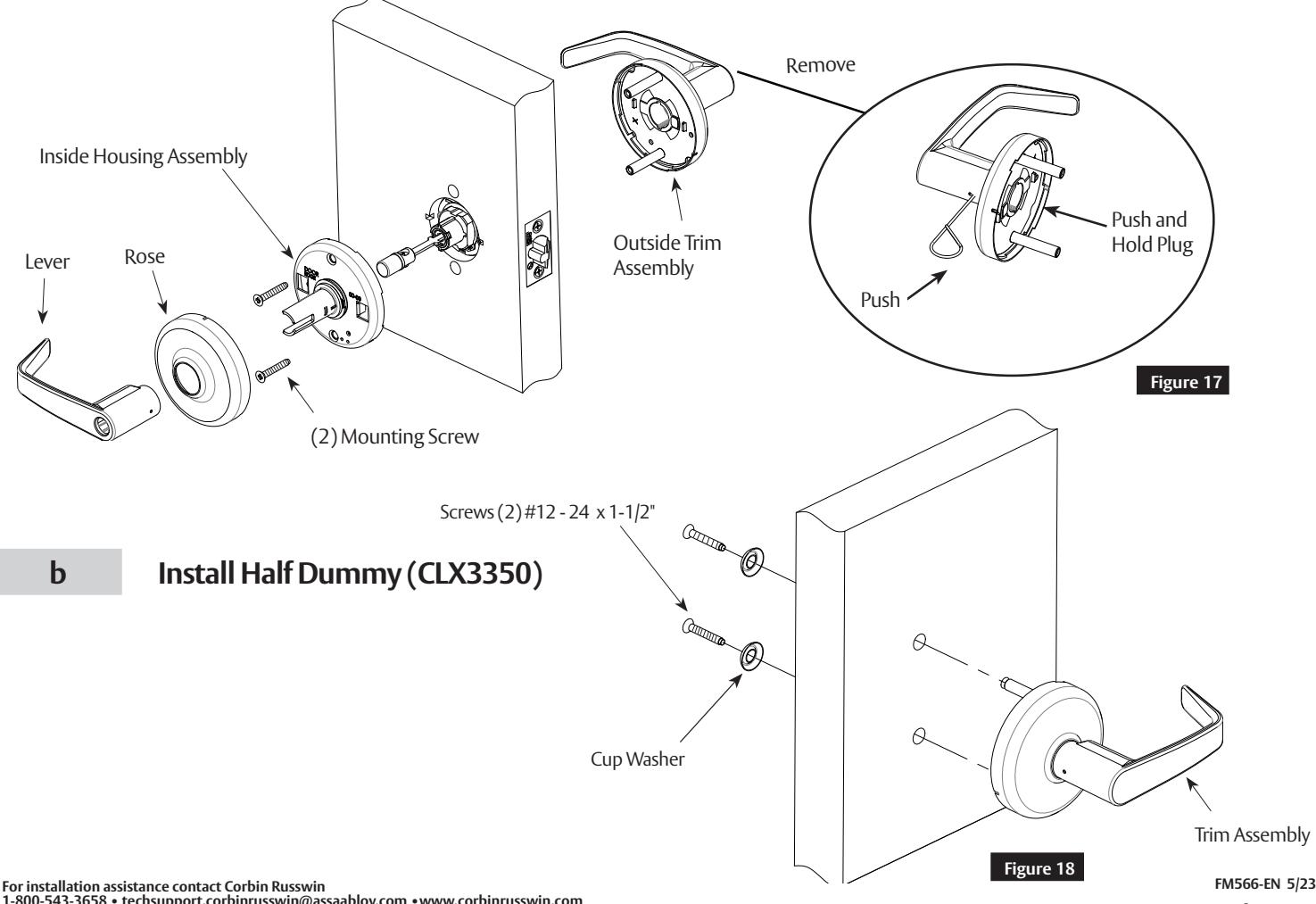
a Remove Outside Lever for Exit Latch (CLX3340NT)
- 1. Remove inside lever (See Section 9).
- 2. Remove rose.
- 3. Remove (2) mounting screws and inside housing assembly.
- 4. Remove outside trim assembly.
- 5. Push and hold plug back (located inside of outside trim assembly). See Figure 17.
- 6. Push lever catch with lever release tool and remove lever.
Cylindrical Lockset
Installation Instructions

11 Other Function Instructions, continued
c Install Full Dummy (CLX3370)
12 Miscellaneous Options
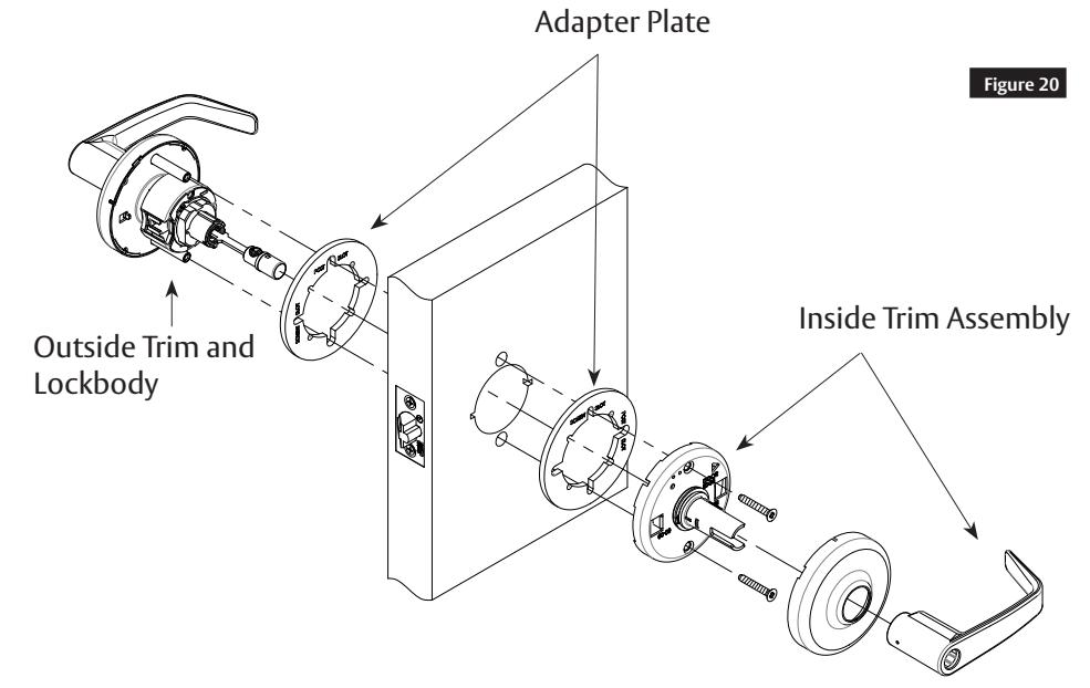
a 1-3/8" Doors (D138)
Install (1) adapter plate between the door and rose assemblies (both sides).
- Inside trim to be aligned with holes marked screw slot.
- Outside trim through-bolts to be aligned with through-bolt holes marked on adapter plate.
Cylindrical Lockset
Installation Instructions

12 Miscellaneous Options
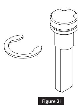
b Lever to Accept Schlage® LFIC (M69)
Provided less core. Tailpiece included (See Figure 21).
- 1. If needed, rotate clip to leave appropriate slot on tailpiece open for locking pin.
- 2. Remove key from core.
- 3. Unscrew threaded cap from end of core. (It will be necessary to depress the locking pin).
- 4. Place tailpiece inside the exposed end of core with locking pin in open slot.
- 5. Reverse step 3 to reinstall cap.
- 6. Install core in lock normally.
See FM207 for more details.
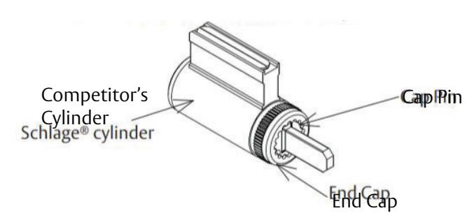
c Lever to Accept Schlage® or Yale® Fixed Core Cylinder (M06 or YC Option)
- 1. Provided less cylinder.
- 2. Depress cap pin and unscrew end cap to remove tailpiece from competitor's cylinder.
- 3. Insert new tailpiece in orientation shown.
- 4. Re-aassemble end cap over new tailpiece.
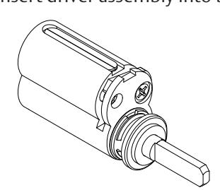
d Lever to Accept Yale® LFIC (YRC Option)
- 1. Provided less cylinder
- 2. Slide provided spacer over tailpiece
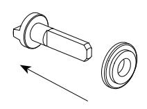
3. Insert driver assembly into back of core.
Cylindrical Lockset
Installation Instructions

12
Miscellaneous Options
e
CLX3329 Hotel Function Timing Adjustment
Timing of the hotel cylinder is set at the factory for the standard door thickness. If the change key or emergency key does not operate properly, follow the steps below:
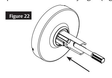
- 1. Set the lock to the unlocked position, remove lever and cylinder from the outside trim. See lever removal instruction on page 4.
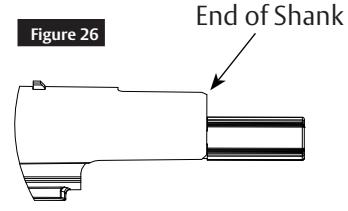
- 2. Insert adjustment tool (provided with lock) into interior cap located within the shank (Figures 22 & 23).
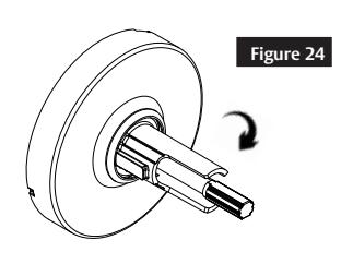
- 3. Rotate cap clockwise until fully tight (Figure 24).
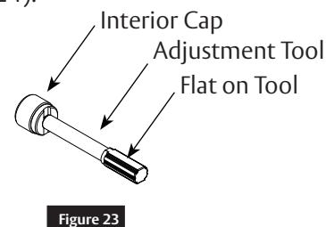
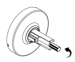
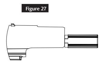
4. Rotate cap back counter-clockwise (Figure 25) until tool handle is approximately in line with the end of the shank as shown in Figure 26 for Fixed Core cylinder (FC) or in Figure 27 for Interchangeable Cylinder (LFIC). The flat on the tool should be at the 12 o'clock position.

- 5. Install cylinder in the lever (see cylinder installation instruction on page 3).
- 6. Turn key 90 degrees counter-clockwise and install lever (with cylinder) onto shank.
-
7. Test to confirm that both the operating and the emergency keys work properly in both the unlocked and locked (pushed/pushed and turn) positions.
- If the operating key is still working in the locked position, the interior cap needs to be turned out (CCW) 1/2 turn.
- If the emergency key is not working in the locked position, the interior cap needs to be turned in (CW) 1/2 turn.
Troubleshooting:
- If having issue fine tuning the adjustment, re-start from #3.
- If cylinder will not install, re-start from #3.

For installation assistance contact Corbin Russwin 1-800-543-3658 • techsupport.corbinrusswin@assaabloy.com • www.corbinrusswin.com
Pour le français, visiter: www.corbinrusswin.com/en/library/installation-instructions.