Corbin Russwin CL3800 Series Key In Lever Installation Instructions
Open the original PDF document
View PDFInstallation Instructions
Corbin 78° Russwin 78°
ASSA ABLOY
Grade 2 Key-In-Lever Cylindrical Lockset CL3800 Series

In U.S.: Corbin Russwin, Inc. 225 Episcopal Road Berlin, CT 06037 USA www.corbinrusswin.com
In Canada: ASSA ABLOY Door Security Solutions Canada 160 Four Valley Drive Vaughan, Ontario, Canada L4K4T9 www.assaabloy.ca
Technical Product Support: Phone: 888-607-5703
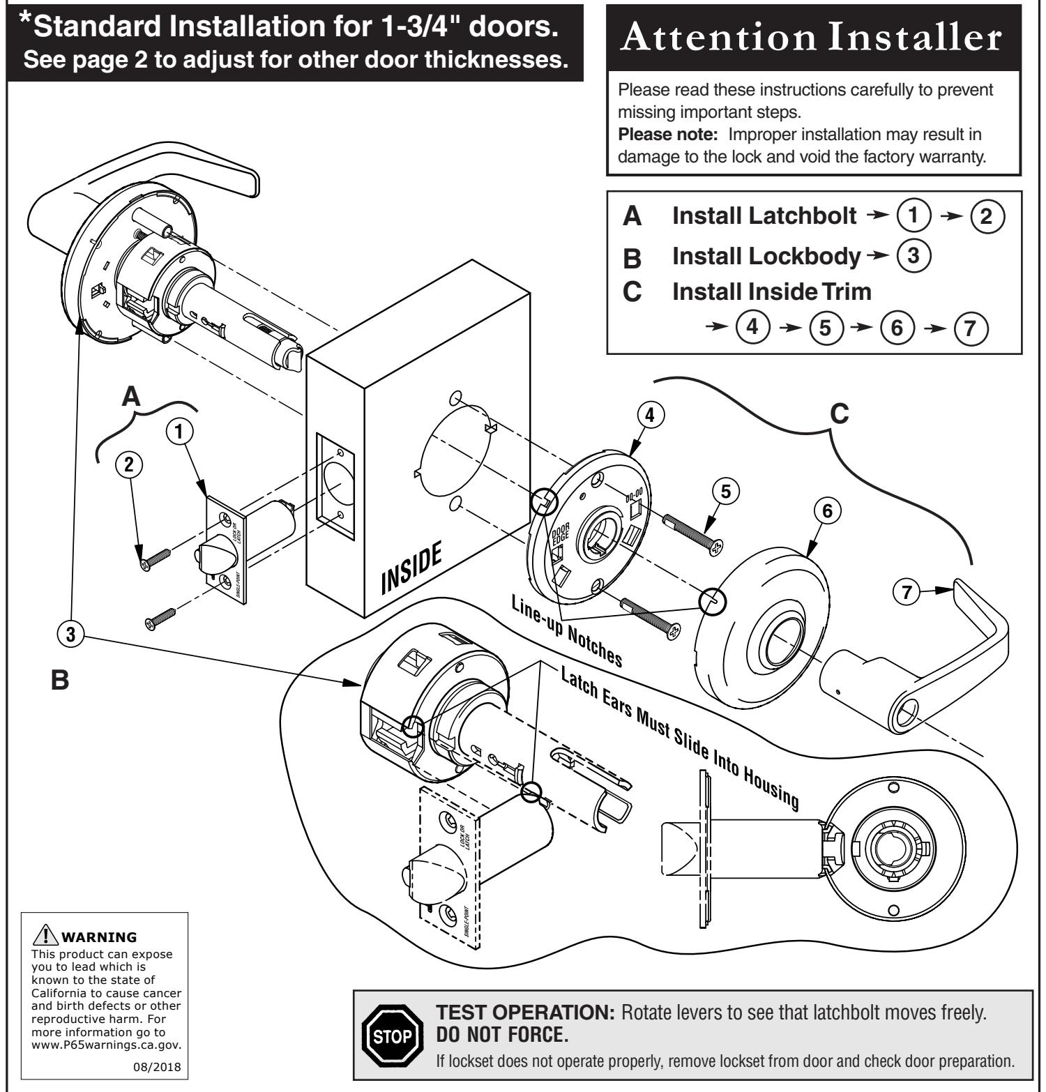
IMPORTANT: The accuracy of the door preparation is critical for the proper functioning and security of this lever handle lock. Misalignment can cause premature wear and a lessening of security.
Door & Frame Preparation
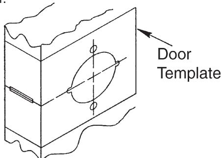
Mark door
Locate and mark horizontal center line at desired height above floor. Fold template over edge of door, centering on horizontal line. Mark centers of holes at proper backset. Mark both sides of the door.
Note:
Be sure to verify backset before marking & drilling door.
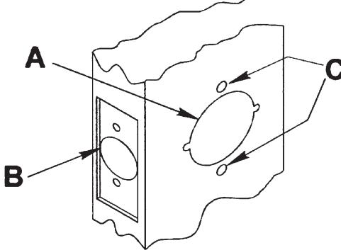
Drill door
- 2-1/8" (54mm) hole thru door. Cut ANSI tab notches as shown on template (except CL3850 and CL3870).
- Drill 1" (25mm) hole in edge of door. Cut out for latch front 5/32" (4mm) deep. 1-1/8" (29mm) wide x 2-1/4" (57mm) high. Check latch unit for proper width front and square or round corners (except CL3850 and CL3870).
- C. Drill two (2) 11/32" (8mm) Dia. holes through door for all functions.
Caution:
To avoid splintering wood doors, drill holes from both sides.
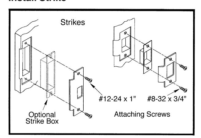
Install Strike
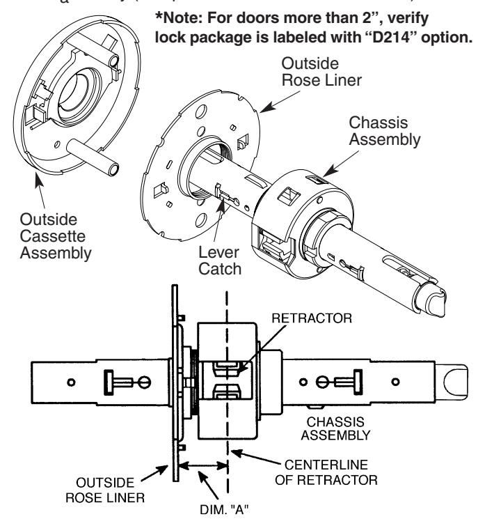
Adjust Lock for Door Thickness

Adjust lock to door thickness (44mm) if other than 1-3/4"
ASSA ABLOY
A. Remove outside lever (see page 4)
doors *. (Lock pre-set from factory for 1-3/4" door).
- B. Slide off outside cassette assembly.
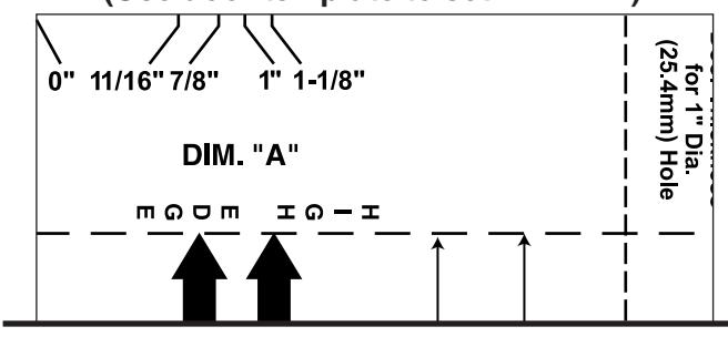
- C. Rotate rose liner to adjust lock to fit door thickness, so that the distance (Dim. "A") from the inside of the liner to the centerline of the retractor is one half of the thickness of the door (see chart and use door marker).
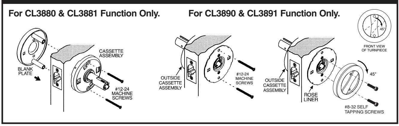
- D. Re-assemble outside cassette assembly onto chassis assembly (except CL3880 and CL3881 functions).
(Use door template to set Dim. "A")
|
Door
Thickness* |
"A" |
Screw
Length |
|---|---|---|
| 1-3/8" (35) | 11/16" (17) | 1-1/2" (38) |
| 1-3/4" (44) | 7/8" (22) | 2" (50) |
| 2" (50) | 1" (25) | 2-1/4" (57) |
| 2-1/4" (57) | 1-1/8" (29) | 2-1/4" (57) |
Dimensions are given in inches (mm).
Cylinder Installation
To Install Interchangeable Core (With lever already installed on lock)
See Figure 2.
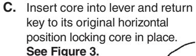
D. Withdraw key. Test lockset for correct function with operating key.
E. Control key has no further use in lockset installation and must be safeguarded for return to Security personnel when installation is complete.
CONTROL KEY
Figure 2
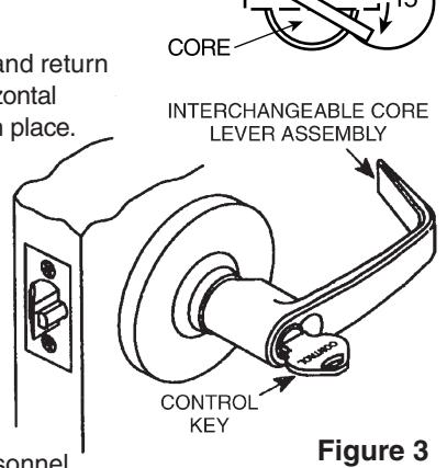
CL3855 Classroom Function Timing Before installing cylinder:
• Turn Cam so points are up and down, 6 o'clock and 12 o'clock
remove cylinder and check cam orientation.
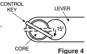
To Remove Interchangeable Core

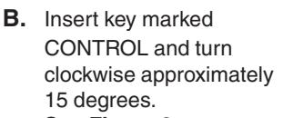
A. Insert key marked CONTROL and turn clockwise approximately 15 degrees. See Figure 4.
B. Pull core and tailpiece completely out of lever.
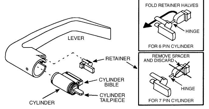
Install Standard Cylinder
Make sure lock is unlocked.
-
A.
Make sure cylinder tailpiece is aligned in same direction as cylinder bible. Slide cylinder all the way into lever.
- For 6-pin cylinder: Fold retainer at hinge and press fit retainer halves together as shown.
- For 7-pin cylinder: Break retainer at hinge and discard spacer section. Also remove black cylinder spacer from inside of chassis rollback for clearance.
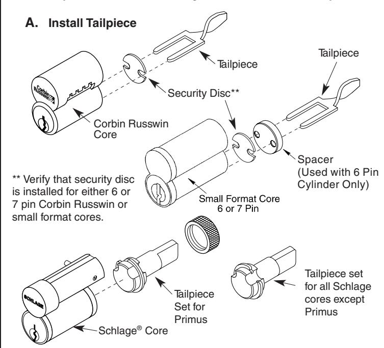
Standard Cylinder Tailpieces
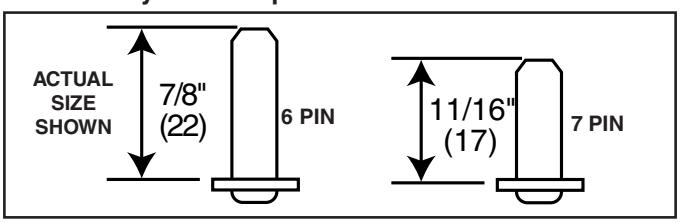
Dimensions are given in inches (mm).
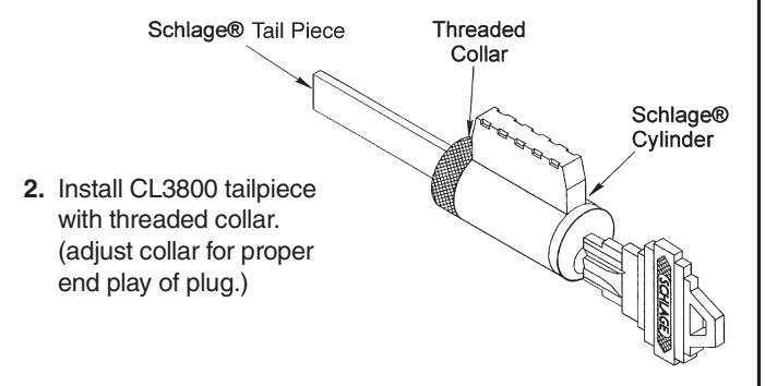
Corbin Russwin conversion kit for Schlage © cylinders with CL3800 lockset.
1. Remove threaded collar and Schlage® tailpiece.
Other product brand names may be trademarks or registered trademarks of their respective owners and are mentioned for reference only.

ASSA ABLOY
| LEVER STYLE | REMOVAL | INSTALL |
|---|---|---|
|
Push /Turn Button
RELEASE TOOL |
Hold in button,
push release tool into release hole, remove lever |
Push button in,
slide lever on. Make sure lever off will not pull |
|
Plain Lever
RELEASE TOOL |
Push release tool
into release hole, remove lever |
Slide lever over
lever catch. Make sure lever will off not pull |
|
Cylinder Lever
RELEASE TOOL |
Rotate key 45°
clockwise (from shed position), Push in release tool into release hole, remove lever |
Insert key and rotate
45° (from shed position), slide lever on. Make sure lever will not pull off |
|
Interchangeable Core Lever
LEVER CATCH (Move in direction of arrow) ROSE LEVER |
Remove cylinder and
tailpiece, (see page 3) Use flat blade screwdriver to pull back lever catch, remove lever |
Slide lever over
lever catch Make sure lever will not pull off |
Optional Installations