Corbin Russwin CL3600 Series Heavy Duty Lever Lockset Installation Instructions
Open the original PDF document
View PDF

CL3600 Series Heavy Duty Lever Lockset
for Functions:
CL3610 CL3629 CL3655 CL3659 CL3682 CL3620 CL3651 CL3657 CL3672
HELPFUL HINT: When facing a door from outside, RH/RHR doors have hinges on the right and LH/LHR doors have hinges on the left.
Disassemble Lockset
A. Remove inside and outside lever by inserting release tool into lever shank hole and depressing lever catch. Slide lever off.
For levers with push or turn buttons: While depressing button, insert release tool into lever shank hole and depress lever catch. Slide lever off.
- B. Remove inside spring cassette from chassis by depressing lever catch with release tool or flat blade screwdriver.
- C. Remove inside rose liner.
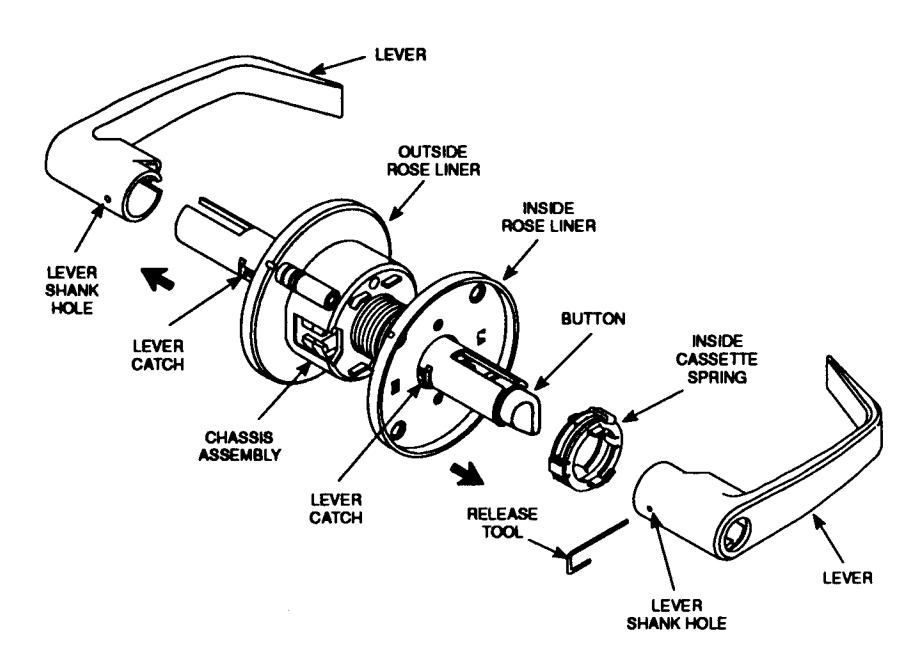
Figure 1
Adjust Lock to Door Thickness For Doors 13/8" – 2" (35 mm – 51 mm)
To adjust for door thickness, turn outside rose liner until the appropriate door thickness indicator line aligns with the chassis housing edge.
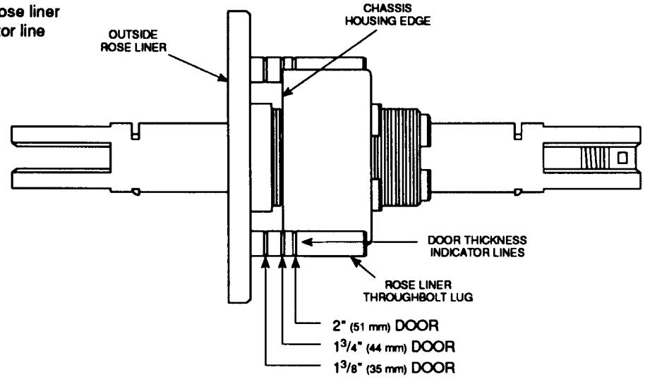
Figure 2
CL3600 Series Heavy Duty Lever Lockset
3.
Mark Door
NOTE: Accurate door prep, including throughbolt holes, is essential for proper operation.
For doors already prepped, make sure prep correctly matches template provided before drilling throughbolt holes.
- A. Locate and mark horizontal and vertical centerlines on door at desired height above floor.
- B. Fold template on dashed line as indicated. Place on HIGH EDGE of door bevel.
C. For non-prepped doors:
- Locate and mark centerline for 1" (25 mm) diameter latchbolt hole on door edge based upon door thickness and desired height above floor.
- Locate and mark centerline for 1" (25 mm) diameter strike hole on door jamb at same height as latchbolt hole.
- Locate and mark centerline for 2<sup>1</sup>/s" (54 mm) diameter cross bore hole on high side of door at height marked for centerline of latchbolt and strike.
D. For all doors:
- Locate and mark center for two <sup>7</sup>/16" (11 mm) diameter throughbolt holes.
- Locate and mark location for two <sup>5</sup>/<sub>32</sub>" (4 mm) square notches on each side of 2<sup>1</sup>/<sub>8</sub>" (54 mm) hole on horizontal axis as shown on template.
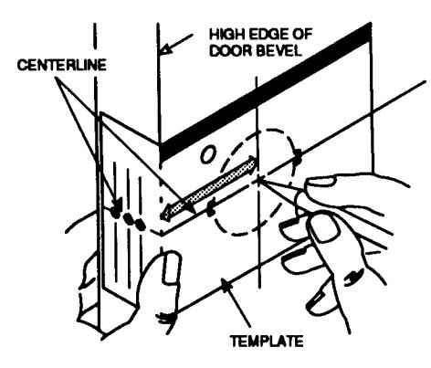
Figure 3-a
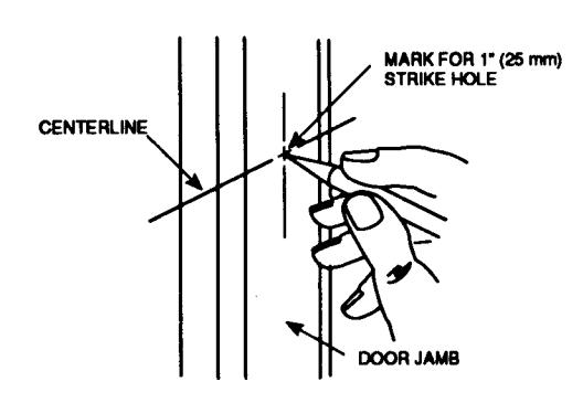
Figure 3-b
4.
Bore Holes
When drilling through door be careful not to damage door finish. Make sure all holes are drilled level and straight.
A. For non-prepped doors:
- Drill ¹/s" (3 mm) pilot hole straight through door where marked for centerline of 2¹/s" (54 mm) cross bore hole.
- Using pilot hole, drill 2<sup>1</sup>/s" (54 mm) cross bore hole straight through door.
- Drill <sup>1</sup>/<sub>8</sub>" (3 mm) pilot hole straight through door edge where marked for centerline of 1" (25 mm) latchbolt hole.
- Using pilot hole, drill 1" (25 mm) hole for latchbolt into edge of door.
- 5. Mortise edge for latch front.
NOTE: Latchbolt hole must be level and perpendicular to the (54 mm) cross bore hole.
B. For all doors:
- Drill two ¹/a" (3 mm) pilot holes straight through door where marked for centerlines of two ²/1e" (11 mm) throughbolt holes.
- Using pilot holes, drill two <sup>7</sup>/16" (11 mm) holes straight through door.
- File two <sup>5</sup>/<sub>32</sub>" (4 mm) square notches into both sides of door at horizontal ends of 2<sup>1</sup>/<sub>8</sub>" (54 mm) hole where marked.
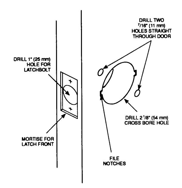
Figure 4
5.
Install Latch
A. Check the door swing and orient the latchbolt to the hand of the door. Note position of latchbolt for hand of door.

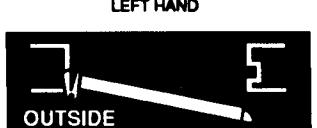


RIGHT HAND REVERSE

B. Insert latchbolt into hole in door as shown and secure with two #8 combination screws provided. Note: For existing doors with a <sup>7</sup>/8" (22 mm) edge bore, remove latchbolt sleeve.
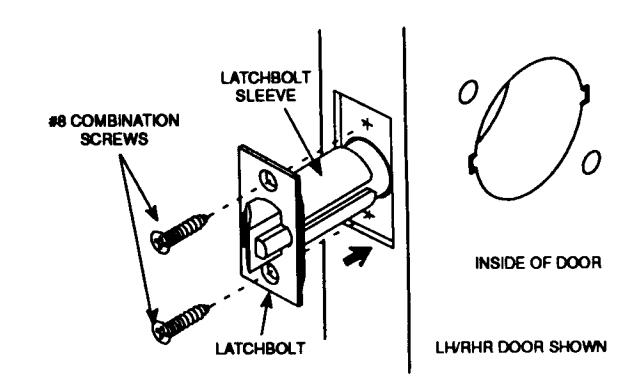
Figure 5
6.
Install Chassis
From outside, insert chassis assembly into cross bore hole. Be sure that the chassis assembly engages latch prongs and latch tail engages retractor as shown in Figure 6-b.
NOTE: Lockset requires adjustment if door thickness is not exactly 1<sup>3</sup>/<sub>4</sub>" (44 mm). To adjust chassis assembly for door thicknesses other than 1<sup>3</sup>/<sub>4</sub>" (44 mm), see Step 2.
IMPORTANT: Chassis assembly must be positioned in center of door.
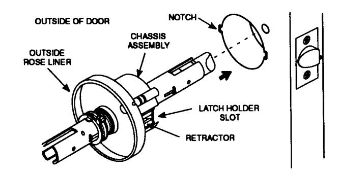
Figure 6-a
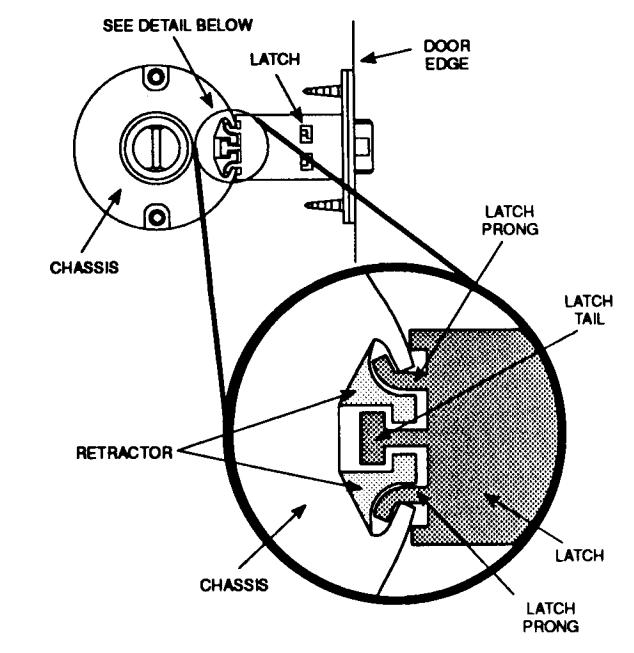
Figure 6-b
7.
Install Inside Rose Liner
- A. Position inside rose liner toward door as shown and attach onto chassis assembly. Make sure that rose liner tabs fit horizontally into slots notched in door.
- B. Insert two #8-32 machine screws into chassis assembly and tighten. Do not overtighten.
- C. For 1³/s" (35mm) thick doors: Insert two #10-24 x <sup>7</sup>/s" (22 mm) machine screws and star washers into throughbolt holes and tighten. For 1³/4" - 2" (44mm - 51 mm) thick doors: Insert two #10-24 x 1¹/s" (29 mm) machine screws and star washers into throughbolt holes and tighten.
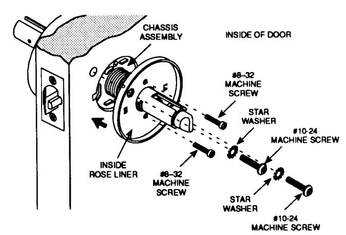
Figure 7

CL3600 Series Heavy Duty Lever Lockset

Test Operation
Rotate chassis rollbacks to see that latchbolt moves freely. DO NOT FORCE. If lockset does not operate properly, remove lockset from door and check door preparation. See Step 6 to re-install lockset.
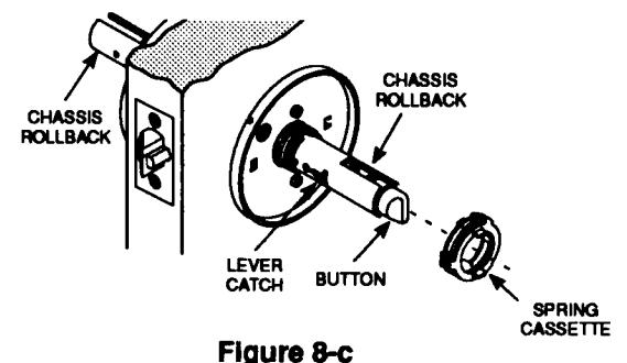
Install Inside Spring Cassette
For all locksets:
- Orient spring cassette with the arrow pointed in toward door. See area of detail Figure 8-a.
- B. Align tab on inside diameter of spring cassette with lever catch. See Figures 8-b and 8-c. Depress lever catch while sliding spring cassette over lever catch. As illustrated in Figure 8-a, spring cassette tab must seat securely in tab slot. For locksets with push or turn buttons: Depress lever catch and button to slide spring cassette over lever catch.
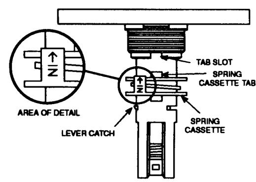
Figure 8-a
Figure 8-b
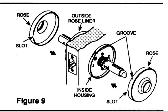
Attach Roses
Note: Ensure spring cassettes are fully engaged prior to installing roses.
- A. Position roses over inside and outside rose liners
- B. Align two grooves on rose sidewalls with two grooves on rose liner sidewalls.
Note: Slots on rose for removal with flat blade screwdriver should be oriented toward edge of door.
C. Press roses firmly onto rose liners so that grooves snap into notches.
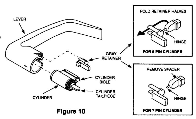
Install Cylinder
Corbin 728°
Note: If no cylinder is to be installed, proceed to Step 11.
-
A. Make sure cylinder tailpiece is aligned in same direction as cylinder bible. Slide cylinder all the way into lever.
- For 6-pin cylinder: Fold gray retainer at hinge and press fit retainer halves together as shown.
- For 7-pin cylinder: Break gray retainer at hinge as shown and discard spacer section.
- B. For all cylinders: Align and position gray retainer in lever shank with prongs facing toward cylinder. Press cylinder retainer firmly into lever shank securing cylinder.
Note: To replace cylinder, see Step 13.
CL3600 Series Heavy Duty Lever Lockset
4 4 Attach Levers
For non-keyed lever:
- A. Insert gray retainer as shown in Figure 11-a.
- B. See Figure 11-b. Align lever shank hole with lever catch. Slide lever assembly onto chassis up to lever catch. Depress lever catch while depressing button (if present) and push lever assembly until lever catch is engaged, securing lever assembly.
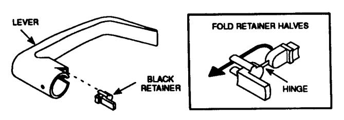
Figure 11-a
For keyed lever:
- A. Insert key into cylinder. Align lever shank hole with lever catch. Slide lever assembly onto chassis up to lever catch. Note: Gently rotating key back and forth 45° will help seat cylinder tallplece into lock body.
- B. See Figure 11-b. Turn key clockwise 45° retracting latch. Note: For classroom function retracting the latch is not required.
- C. Depress lever catch and push lever assembly until lever catch is engaged, securing lever assembly.
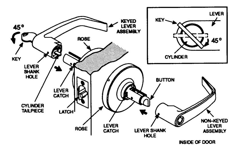
Figure 11-b
4 \( \) Locate and Install Strike
For non-prepped doors:
- A. Locate centerline of strike opening on door jamb at centerline of latchbolt. Trace outline around the strike on door jamb.
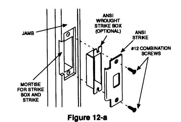
- B. Mortise door jamb to accommodate strike box and ANSI strike – see Figure 12-a (or optional curved lip box strike – see Figure 12-b) in alignment with center of latchbolt.
For all doors:
Insert strike box if required and fasten ANSI strike (or optional curved lip box strike) with combination screws provided.
Note: When strike box is not used, recess in door jamb must be at least 1/2" (13 mm) deep to allow latchbolt to extend to its full free length.
OPTIONAL CURVED LIP BOX STRIKE WORTISE FOR STRIKE
Figure 12-b

LOCKSET INSTALLATION IS NOW COMPLETE.
CL3600 Series Heavy Duty Lever Lockset
Replace Cylinder (If Required)
- A. Insert key into cylinder and rotate 45°. Maintain angle and depress lever catch with release tool through lever shank hole. Pull to remove outside lever assembly.
- B. Remove gray retainer from lever assembly. Slide cylinder out of lever.
To install cylinder, see Step 10.
To attach lever assembly to lockset, see Step 11.
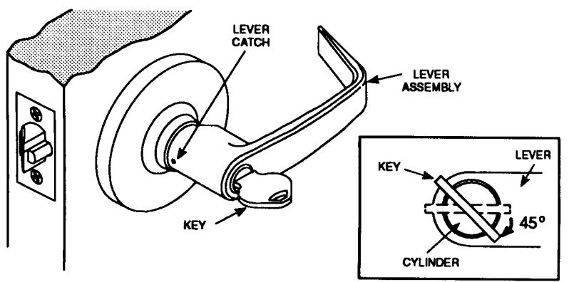
Figure 13

In U.S.: Corbin Russwin, Inc. 225 Episcopal Road Berlin, CT 06037 USA Phone: 860-225-7411 Fax: 860-828-7266
In Canada: Yale-Corbin Canada LTD. 3160 Orlando Drive Mississauga, Ontario, Canada L4V1R5 Phone: 905-672-6220 Fax: 905-672-9022