Corbin Russwin CL3300 Series Cylindrical Locks Installation Instructions_FM533
Open the original PDF document
View PDF

CL3300 Series
ANSI/BHMA Grade 1
Key-In-Lever
CL3300 Series
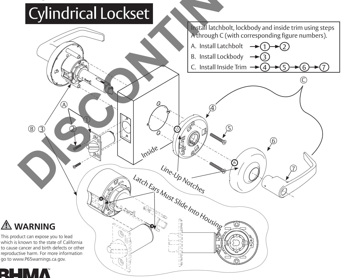
Cylindrical Lockset
Installation Instructions

| TOC | Table of Contents | |
|---|---|---|
| 1 | Door and Frame Preparation 3 | |
| a | Mark Door 3 | |
| b | Drill Door and Install Strike 3 | |
| 2 | Adjust Lock for Door Thickness 3 | |
| 3 | Cylinder Installation 4 | |
| a | CL3355 Classroom or CL3352 Intruder (Outside Cylinder) Function Timing 4 | |
| b | Interchangeable Core Installation 4 | |
| c | Interchangeable Core Removal 5 | |
| d | Install Standard Cylinder 5 | |
| e | Conversion Kit for Schlage® Cylinders with CL3300 Lockset 5 | |
| 4 | Lever Removal and Installation 6 | |
| 5 | Optional Installations 7 |
ATTENTION INSTALLER
- Read these instructions carefully to prevent missing important steps.
- Improper installation may result in damage to lock and void factory warranty.
STOP - TEST OPERATION:
- Rotate levers to see that latchbolt moves freely. DO NOT FORCE.
- If lockset does not operate properly, remove lockset from door and check door preparation.

1 Door and Frame Preparation
a Mark Door
- 1. Locate and mark horizontal center line at desired height above floor.
- 2. Fold template over edge of door, centering on horizontal line.
- 3. Mark centers of holes at proper backset. Mark both sides of door. (Figure 1)
IMPORTANT
- The accuracy of door preparation is critical for proper functioning and security of this lever handle lock. Misalignment can cause premature wear and a lessening of security.
- Standard installation is for 1-3/4" doors. (See "Adjust Lock for Door Thickness" on page 3 for other door thicknesses).
Attaching Screws
Door
Template
Mark
holes
Note:
Be sure to verify backset before marking and drilling door.
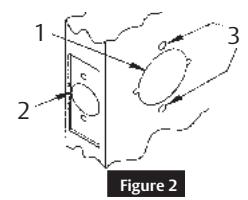
b Drill Door and Install Strike
- 4. Drill a 2-1/8" (54 mm) hole through door. Cut ANSI tab notches as shown on template (except CL3350 and CL3370).
- 5. Drill 1" (25 mm) hole in edge of door. Cut out for latch front 5/32" (4 mm) deep and 1-1/8" (29 mm) wide x Optional Strike Box 2-1/4" (57 mm) high. Check latch unit for proper width front and square or round corners (except CL3350 and CL3370).
- 6. Drill two (2) 11/32" (8 mm) diameter holes through door for all functions.Install strike. (Figure 2 and Figure 3)
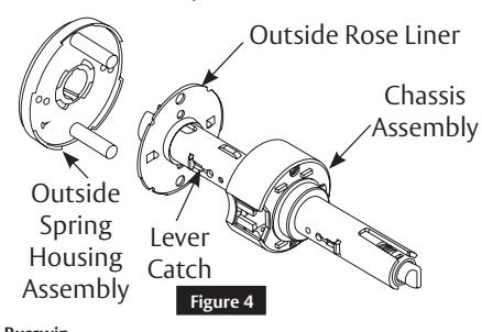
Adjust Lock for Door Thickness
Lock will be factory preset for 1-3/4" (44 mm) doors unless specified.
To adjust lock to door thickness if other than 1-3/4" (44 mm) doors:
- 1. Remove outside lever. (see page 6)
- 2. Slide off outside spring housing assembly.
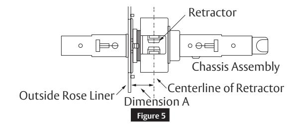
- 3. Rotate rose liner to adjust lock to fit thickness, so distance (Dimension A) from inside liner to centerline of retractor is half the thickness of the door (see chart in step 4 on page 3).
- 4. Reassemble outside spring housing assembly onto chassis assembly (not for CL3380 and CL3381 functions).
Mark
center
of hole
Strikes
| Door Thickness | Dimension A |
|---|---|
| 1-3/4 " (44 mm) | 7/8 " (22 mm) |
| 2 " (50 mm) | 1 " (25 mm) |
| 2-1/4 " (57 mm) | 1-1/8 " (29 mm) |
FM533 02/20
3
3 Cylinder Installation
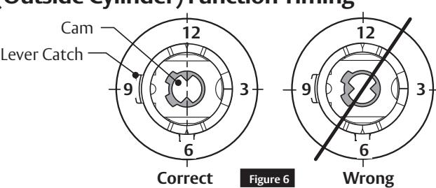
a CL3355 Classroom or CL3352 Intruder (Outside Cylinder) Function Timing
Before installing cylinder:
• Turn cam so points are up and down, 6 o'clock and 12 o'clock. (Figure 6)
After installing cylinder:
- Confirm key rotates 180° both ways.
- If cylinder rotates 360°, remove cylinder and check cam orientation.
b Interchangeable Core Installation
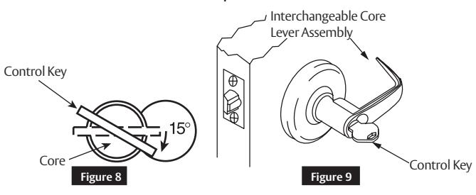
- 1. Install tailpiece. ( Figure 7)
- 2. Insert key marked CONTROL and turn clockwise approximately 15°. (Figure 8 )
- 3. Insert core into lever and return key to its original horizontal position locking core in place. (Figure 9 )
- 4. Withdraw key.
- 5. Test lockset for correct function with operating key.
- 6. Control key has no further use in lockset installation and must be safeguarded for return to security personnel when installation is complete.
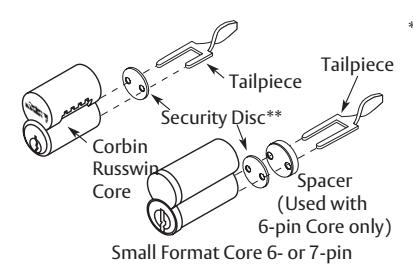
** Verify that security disc is installed for either 6-pin or 7-pin Corbin Russwin or small format cores.
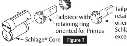
Tailpiece with retaining ring oriented for all Schlage cores except Primus
FM533 02/20

Figure 10
Cylinder Installation (continued)
Interchangeable Core Removal
- 1. Insert key marked CONTROL and turn clockwise approximately 15°. (Figure 10)
- 2. Pull core and tailpiece completely out of lever.
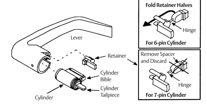
d Install Standard Cylinder
- 1. Make sure lock is unlocked.
- 2. Make sure cylinder tailpiece is aligned in same direction as cylinder bible.
-
3. Slide cylinder all the way into lever.
- For 6-pin cylinder: Fold retainer at hinge and press fit retainer halves together as shown.
- For 7-pin cylinder: Break retainer at hinge and discard spacer section. Also remove black cylinder spacer from inside of chassis rollback for clearance.
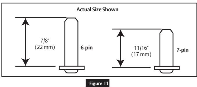
Standard Cylinder Tailpieces
Note:
Dimensions are given in inches (") and millimeters (mm).
Control Key
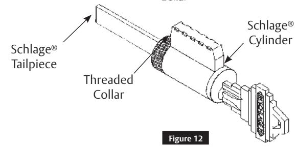
Conversion Kit for Schlage® Cylinders with CL3300 Lockset
- 1. Remove threaded collar and Schlage® tailpiece.
- 2. Install CL3300 tailpiece with threaded collar.
- 3. Adjust collar for proper end play of plug.

4 Lever Removal and Installation
| Lever Style | Removal | Install |
|---|---|---|
|
Push / Turn Button
Release Hole Lever Assembly Button |
Hold in button, push release tool
into release hole, remove lever. |
Push button in, slide lever on.
• Make sure lever will not pull off. |
|
Plain Lever
Release Hole Lever Assembly |
Push release tool into release hole,
remove lever. |
Push button in, slide lever on.
• Make sure lever will not pull off. |
|
Cylinder Lever
Release Hole Lever Assembly Key |
Rotate Key 45˚ clockwise (from
shed position). Push release tool into release hole, remove lever. Lever Key 45˚ Cylinder |
Push button in, slide lever on.
• Make sure lever will not pull off. |
|
Interchangeable Core Lever
Lever Catch (Move in direction of arrow) Rose Lever |
Remove cylinder and tailpiece (see
page 4). Use flat-head screwdriver to pull back lever catch, remove lever. |
Push button in, slide lever on.
• Make sure lever will not pull off. |
FM533 02/20
or in part without the express written permission of ASSA ABLOY Access and Egress Hardware Group, Inc. is prohibited.

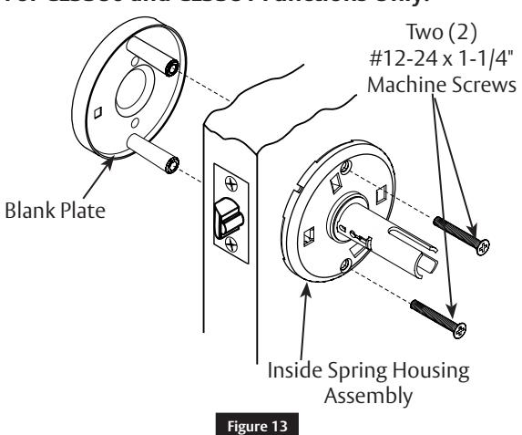
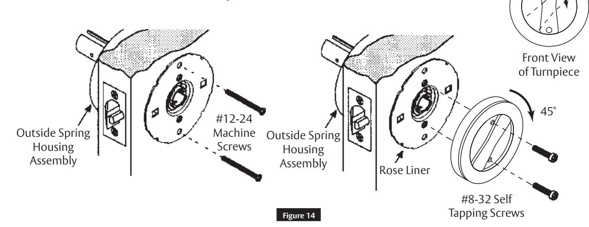
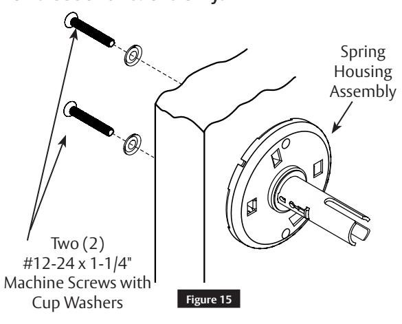
5 Optional Installations
For CL3380 and CL3381 Functions Only:
For CL3390 and CL3391 Functions Only:
For CL3350 Functions Only:
For CL3370 Functions Only:
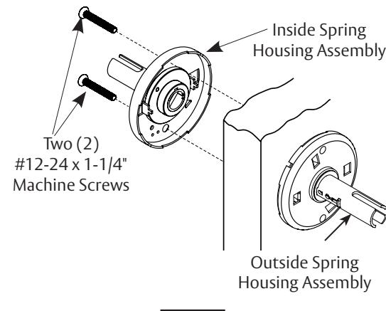
Figure 16
The ASSA ABLOY Group is the global leader in access solutions. Every day, we help billions of people experience a more open world.
ASSA ABLOY Opening Solutions leads the development within door openings and products for access solutions in homes, businesses and institutions. Our offering includes doors, frames, door and window hardware, locks, perimeter fencing, access control and service.

Corbin Russwin, Inc. 225 Episcopal Road Berlin, CT 06037 USA Phone: 800-543-3658 Fax: 800-447-6714 www.corbinrusswin.com
ASSA ABLOY is the global leader in door opening solutions, dedicated to satisfying end-users needs for security, safety, and convenience