Corbin Russwin CL3100 Series Cylindrical Locks Installation Instructions_FM345
Open the original PDF document
View PDFInstallation Instructions

CL3100 Series
Grade 1 Key-In-Lever
VR Lever Lock

This product can expose you to lead which is known to the state of California to cause cancer and birth defects or other reproductive harm. For more information go to www.P65warnings.ca.gov.
CL3100 Series
Installation Instructions

| TOC | Table of Contents | ||
|---|---|---|---|
| 1 | Standard Installation | 3 | |
| a | Install Latchbolt, Lockbody and Inside Trim | 3 | |
| 2 | Door and Frame Preparation | 4 | |
| a | Mark Door | 4 | |
| b | Drill Door | 4 | |
| c | Install Strike | 4 | |
| 3 | Lock Disassembly | 5 | |
| 4 | Latch Installation | 5 | |
| 5 | Driver Tip Alignment | 5 | |
| 6 | Sleeve Installation | 6 | |
| 7 | Cam Orientation | 7 | |
| 8 | Rose Installation | 7 | |
| 9 | Lever Installation | 8 | |
| 10 | CL3152 Classroom Intruder Operation Check | 9 | |
| 11 | Cylinder Removal (Conventional) | 9 | |
| 12 | CL3120 Outside Lever Removal | 9 | |
| 13 | IC Cylinder and Levers - Installation / Removal 10-11 | ||
| a | Remove IC Core | 10 | |
| b | Remove IC Core Lever | 10 | |
| c | Install IC Core Lever | 10 | |
| d | Insert IC Core | 11 | |
| 14 | Installation: CL3100 Lever Lock with High Security Lever (M111) 12-13 | ||
| a | Assemble Lock Body | 12 | |
| b | Install Security Attachment Screw | 12 | |
| c | Install Lever | 12 | |
| d | Remove Cylinder | 13 | |
| 15 | Dummy Trim Installation | 13 | |
| CL3150/70 Half/Full Dummy Trim C, E and K Rose | 13 | ||
| CL3150/70 Half/Full Dummy D Rose | 14 |
Attention Installer
Please read these instructions carefully to prevent missing important steps.
Notes
- Improper installation may result in damage to lock and void factory warranty.
- Other product brand names may be trademarks or registered trademarks of their respective owners and are mentioned for reference only.
To view the QR Code video clips within this document, download a free mobile app and scan the QR Code with your mobile device. The complete video can be viewed on YouTube at https://youtube/mrbX3uF49GM .
CL3100 Series
Installation Instructions

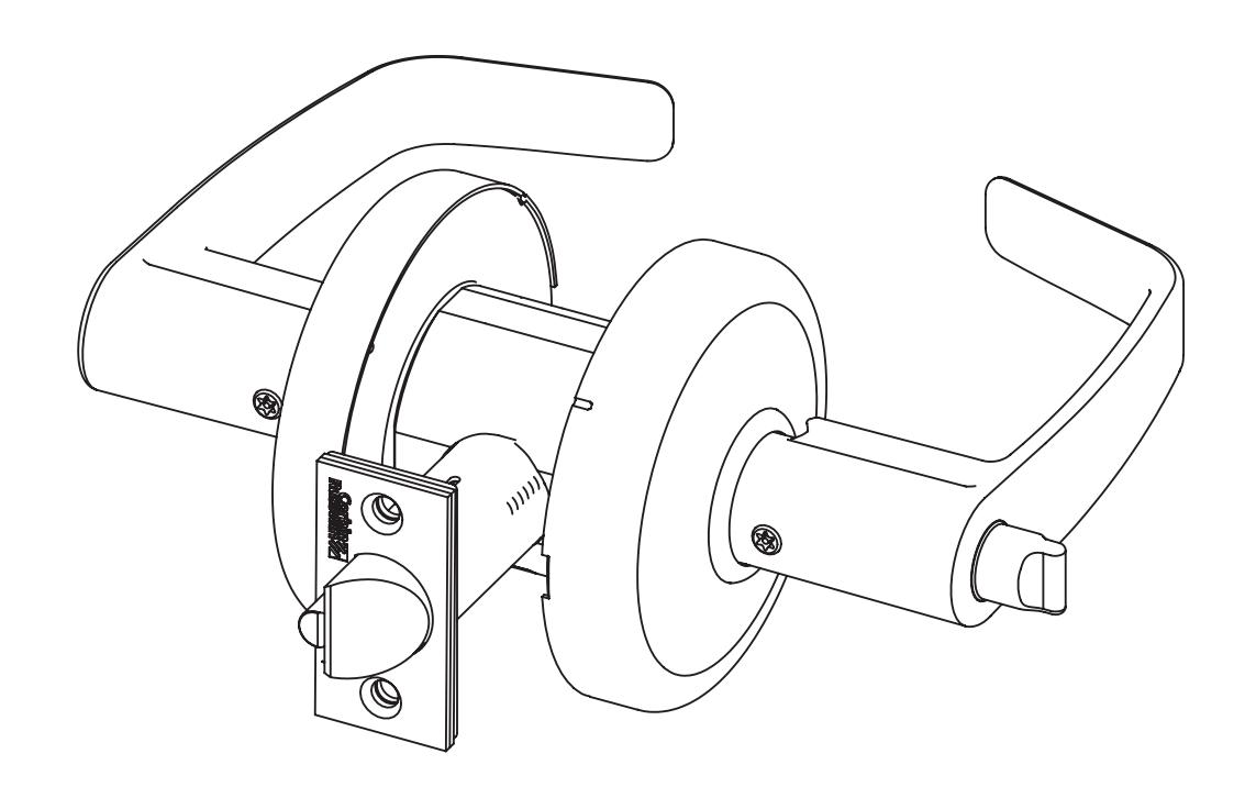
1 Standard Installation
a Install Latchbolt, Lockbody and Inside Trim
Important
The accuracy of door preparation is critical for proper functioning and security of lever handle lock. Misalignment can cause premature wear and lessening of security.
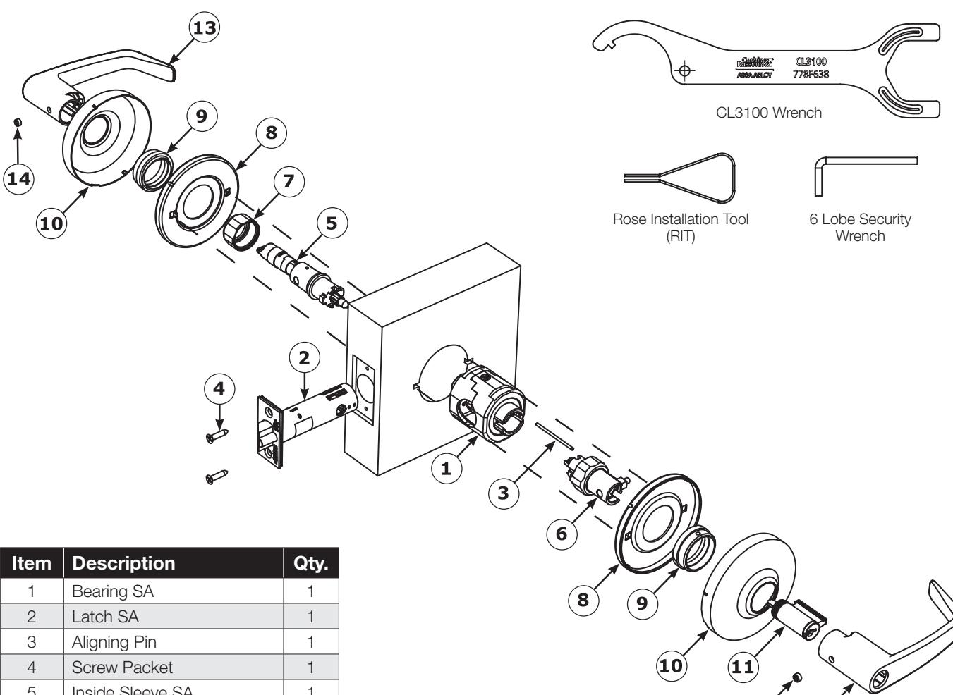
Inside Sleeve SA 1 Outside Sleeve SA 1 Collar, Sleeve SA 1 Plate, Rose Support 2 Collar, Rose Support Plate 2 10 Rose 2 Cylinder 1 Outside Lever 1 Inside Lever 1 6 Lobe Security Set Screw 1/4-28 x 11/64 2
Figure 1 CL3100 Cylinder Installation - Standard Installation

TEST OPERATION:
Rotate levers to be sure latchbolt moves freely.
DO NOT FORCE.
If lockset does not operate properly, remove lockset from door and check door preparation.
CL3100 Series
Installation Instructions

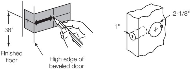
Beveled door
2
Door and Frame Preparation
a
Mark Door
- Fold door marker (FM347) on the door and mark the hole centers.
- Bore 2-1/8" hole.
- Bore 1" hole.
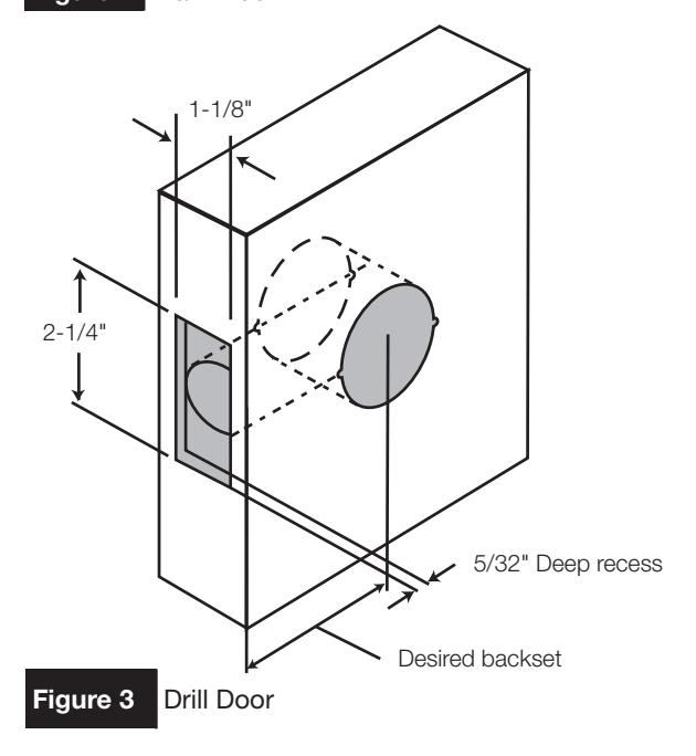
b
Drill Door
• Cut rectangular front recess.

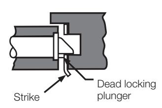
C
Install Strike
- Mark recess for latch bolt.
- Mark outline of strike.
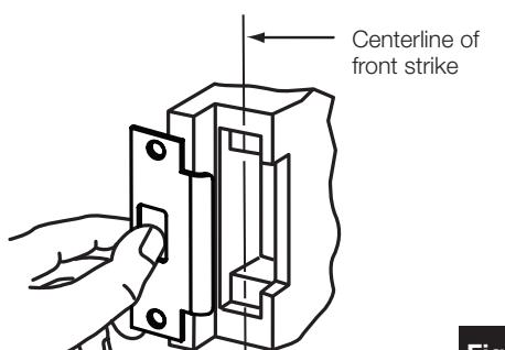
Figure 4 Install Strike
- Cut recess for latch bolt.
- Install strike; secure with two (2) screws.
IMPORTANT
Dead locking plunger stops on strike when door is closed.
CL3100 Series
Installation Instructions

Lock Disassembly
- 1. Unthread and remove INSIDE collar and sleeve.
- 2. Unthread and remove OUTSIDE collar and sleeve.
Note
Push aligning pin out of the way of outside collar.
- 3. Remove aligning pin from bearing assembly.
- 4. Separate latch from bearing assembly.
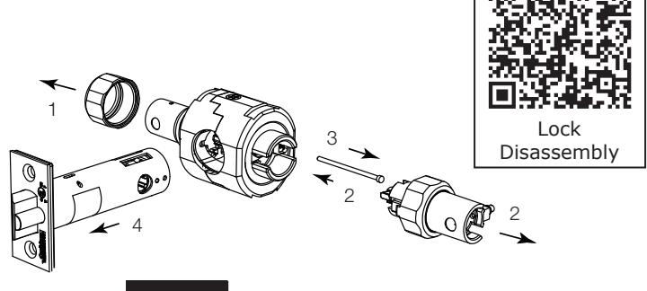
Figure 5 Lock Disassembly
Latch Installation
Hold door open with door stop.
- 1. Insert bearing assembly.
- 2. Insert latch assembly.
- 3. Insert aligning pin from secure side (outside) of door.
- 4. Install latch plate screws. Do not tighten completely until lock installation is finished.
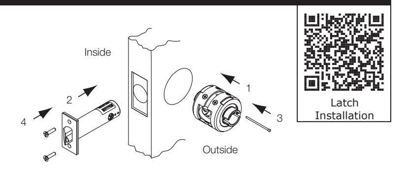
Figure 6 Latch Installation
Driver Tip Alignment

IMPORTANT:
Sleeves with colored driver tips require that the slotted cam be rotated, allowing the spring loaded spline adapter to move freely in and out of the outside sleeve.
Driver tips with red markings must match up before assembling lock. Test to ensure that spline adapter can move freely.
Some driver tips have two (2) color markings for function identification. See chart on the following page.
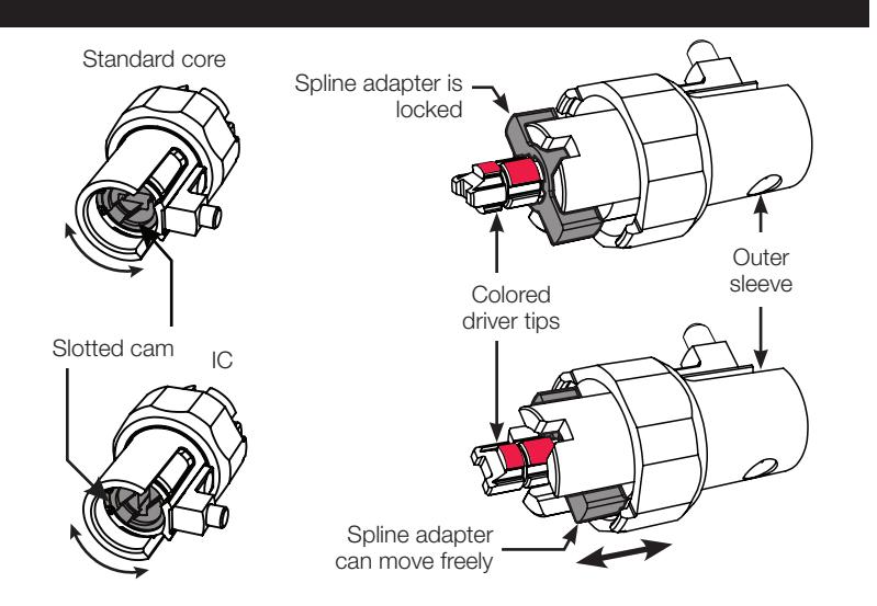
Figure 7 Driver Tip Alignment
CL3100 Series
Installation Instructions

Function Specific Instructions - Sleeve Installation
See Specific Instructions Per Function. Identify Function On Box. (Example: CL3151)
For functions not shown, proceed to step 6, sleeve installation.
| Outside Sleeve |
Driver
Tip Color |
Function
Number |
Function
Description |
Inside Sleeve |
|---|---|---|---|---|
| NONE | CL3132 | Utility/Institutional | Align driver tips matching the painted sections (page 5 step 5) and orient cam to depress lever catch button (page 7 step 7). | |
| Align driver tips and orient the cam as illustrated on | RED | CL3157 | Storeroom/Closet | |
| page 5 step 5. Spline adapter will move freely. | RED | CL3172 |
Exits/Public Toilets/
Apartment |
|
| wiii move neery. | RED | CL3151 | Entrance/Office | |
| RED | CL3161 | Entrance/Office | ||
| RED | CL3193 | Service Station | Sleeve Installation (page 6 step 6) | |
| Align driver tipe |
RED and
BLUE |
CL3120 |
Privacy/Bedroom/
Bathroom |
|
| Align driver tips (page 5 step 5). Spline adapter will move freely. |
RED and
GREEN |
CL3152 | Classroom Intruder | |
| auapter will move freely. |
RED and
GREEN |
CL3175 |
Corridor/Dormitory
Lock |
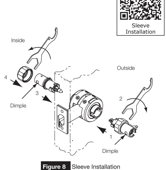
Sleeve Installation
- 1. With driver tips aligned, insert outside sleeve first. Dimple must face door edge.
- 2. Thread outside collar by hand. Tighten to bearing assembly with wrench.
- 3. Insert inside sleeve. Dimple must face door edge.
- 4. Thread inside collar by hand. Tighten to bearing assembly with wrench.
CAUTION
If excessive wrench torque is required, stop and check alignment of driver tips: page 5 step 5.
CL3100 Series
Installation Instructions

Cam Orientation
- 1. Lock lever by button, if applicable.
- 2. Turn slotted cam until lever catch button can be depressed.
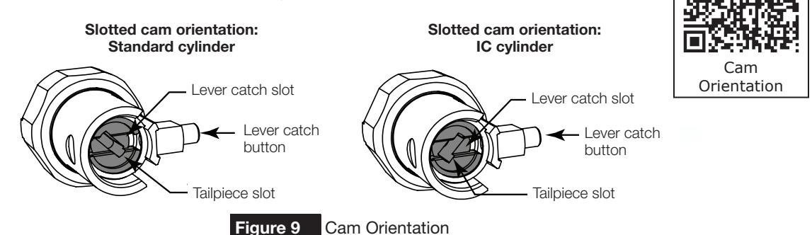
Figure 9
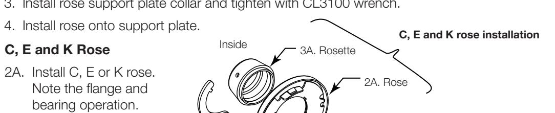
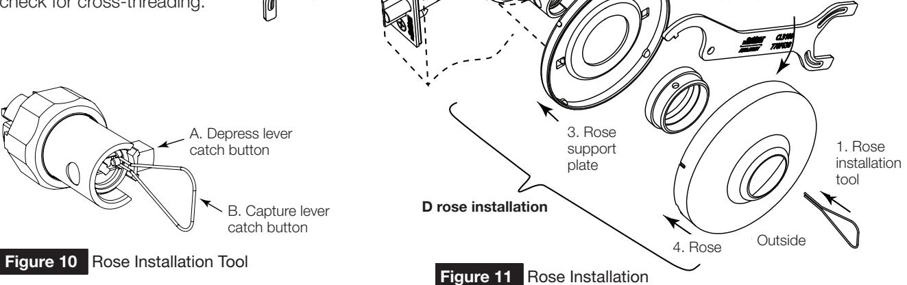
Rose Installation
D Rose
- 1. Orient cam and depress lever catch button (see cam orientation diagram page 7 step 7). The lever catch button will slide into the lever catch slot in the cam. Use the rose installation tool (RIT) to retain the lever catch button - see Figure 10 below for RIT instructions (for D rose installation only). Lock lever by button, if applicable.
- 2. Install rose support plate. Note the flange orientation and door prep.
- 3. Install rose support plate collar and tighten with CL3100 wrench.

D Rose Installation
CAUTION
If excessive wrench torque is required, stop and check for cross-threading.
3A. Install rosette and tighten
with the CL3100 wrench.
For Installation Assistance contact Corbin Russwin 1-888-607-5703 • techsupport.corbinrusswin@assaabloy.com
Bearing assembly
1. Lever catch button
3. Tighten rose
support plate
CL3100 Series
Installation Instructions

Function Specific Directions - Lever Installation
For functions not shown, proceed to step 9, Lever Installation.
| Inside Sleeve |
Function
Number |
Function
Description |
Outside Sleeve |
|---|---|---|---|
| Lock lever by button. | CL3120 |
Privacy/Bedroom/
Bathroom |
Rotate cam with emergency key until lever catch button can be depressed. |
| CL3161 | Entry/Office | ||
| CL3151 | Entrance/Office | Rotate cam until lever catch button | |
| CL3193 | Service Station | can be depressed. | |
| CL3157 | Storeroom/Closet | ||
|
Align tailpiece and tailpiece slot in cam.
Rotate key 45° CW until lever catch button can be depressed. Install lever. |
CL3132 | Utility/Institutional | Align tailpiece and tailpiece slot in cam. Rotate key 45° CW until lever catch button can be depressed. Install lever. |
| Rotate cam CCW until it stops. | CL3172 |
Exits/Public Toilets/
Apartment |
Rotate cam until lever catch button can be depressed. |
| Rotate cam CCW until it stops. Then rotate back 45° until lever catch button can be depressed. | CL3162 | Communicating | Rotate cam CCW until it stops. Then rotate |
| Rotate cam CCW until it stops. | CL3152 | Classroom Intruder | back 45° until lever catch button can be |
| CL3155 | Classroom | depressed. | |
| CL3175 | Corridor/Dormitory Lock |
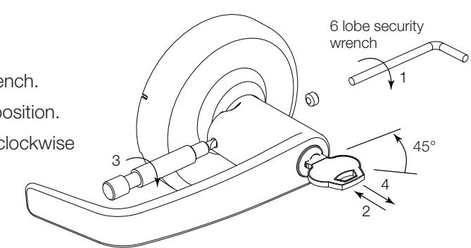
9 Lever Installation
For conventional cylinder, place cylinder into lever. Insert key and turn 45° CLOCKWISE to align cylinder tailpiece with cylinder tailpiece slot in cam (cam orientation - page 7 step 7).
NOTE
6-pin standard cylinder requires a spacer for cylinder to seat properly in the lever. For IC cylinder/lever removal and installation, see page 10 step 13.
- 2. Install outside lever. Push on lever until lever engages.
- 3. Secure with 6 lobe security set screw until tight.
- 4. Install inside lever.
- 5. Secure with 6 lobe security set screw until tight.
- 6. Complete tightening of two (2) latch bolt screws.
- 7. Check operation of levers and latch bolt before closing door.
STOP f
TEST OPERATION:
Rotate levers to see that latchbolt moves freely. D0 NOT FORCE. If lockset does not operate properly, remove lockset from door and check door preparation.
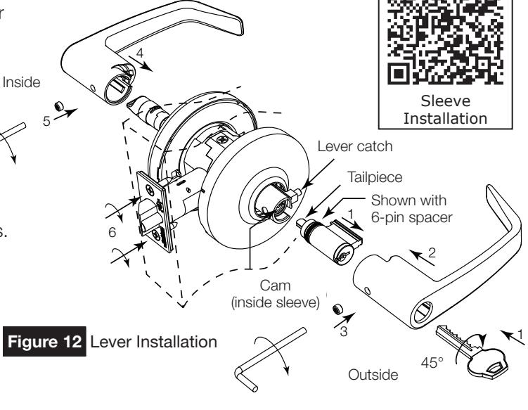
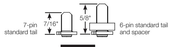
Figure 13 Lever Tails
FM345 01/19
CL3100 Series
Installation Instructions

10 CL3152 Classroom Intruder Operation Check
Note
When inside key locks outside lever, outside key retracts the latchbolt but cannot unlock the outside lever. Outside key must be rotated back completely clockwise before removing the key.
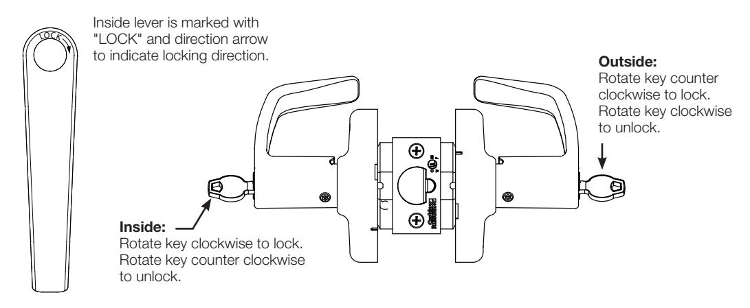
Figure 14 Classroom Intruder Operation Check
11 Cylinder Removal (Conventional)
- 1. Remove 6 lobe security set screw.
- 2. Insert key and rotate 45° clockwise to release lever catch.
- 3. Depress lever catch and remove lever.
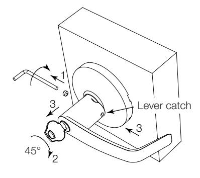
Figure 15 Cylinder Removal
Note
Interchange core cylinders do not require removing the lever to remove (page 11 step 13D).
12 CL3120 Outside Lever Removal
- 1. Remove 6 lobe security set screw.
- 2. Orient cam in outside sleeve with flat blade screwdriver to release lever catch button (page 7 step 7).
- 3. Depress lever catch and remove lever.
CL3100 Series
Installation Instructions

13 IC Cylinder and Levers - Installation / Removal
Corbin Russwin Interchangeable Cores (C6, CL6, CT6, CTP, C7, CL7, CT7) Small Format Interchangeable Cores SFIC (M08). Schlage LFIC (M69). Yale LFIC (YRC, YRC7)
a Remove IC Core
- 1. Insert control key and turn counter clockwise until stop is reached.
- 2. With key in this position, pull out core.
- 3. Remove key.
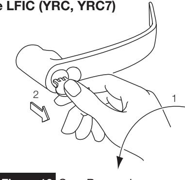
Figure 16 Core Removal
b Remove IC Core Lever
- 1. Remove cylinder (as above).
- 2. Remove 6 lobe security set screw.
- 3. Use a flat blade screwdriver to rotate cam within lever sleeve 45° clockwise to align lever catch slot with lever catch button. (See cam orientation page 7 step 7).
- 4. Depress catch and remove lever.
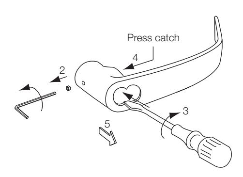
Figure 17 Core Lever Removal
c Install IC Core Lever
1. Assemble lever onto sleeve.
Note
If IC core is available, insert it into the lever first (see 13D).
- 2. Use a flat blade screwdriver (or, with the IC core in the lever, use the key and turn to engage the tailpiece and slot) to rotate cam within lever sleeve 45° clockwise to align wide slot with lever retainer catch.
- 3. Push lever until catch engages. Check engagement.
- 4. Secure with 6 lobe security set screw.
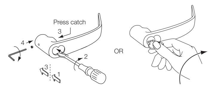
Figure 18 Core Lever Installation
CL3100 Series
Installation Instructions

13 IC Cylinder and Levers - Installation / Removal (cont.)
d Insert IC Core
- 1. Insert 6- or 7-pin tailpiece, with appropriate spacer disk, into the two (2) holes on the back of the cylinder core. (See spacer type below).
- 2. Insert control key and turn counter clockwise.
- 3. Slide core into lever. If core will not fully insert, the cam may need adjustment for proper tailpiece - slot alignment.
- 4. Rotate control key clockwise to lock in lever.
- 5. Remove control key. Hold cylinder with finger and remove key. Figure 19 Core Lever Installation
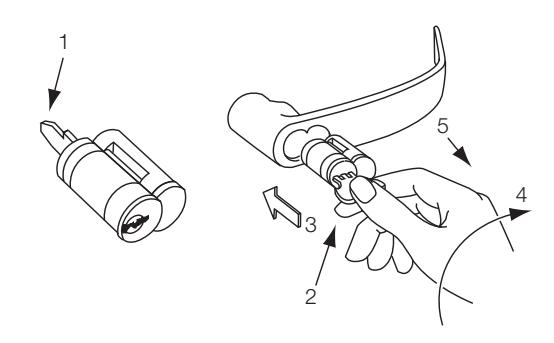
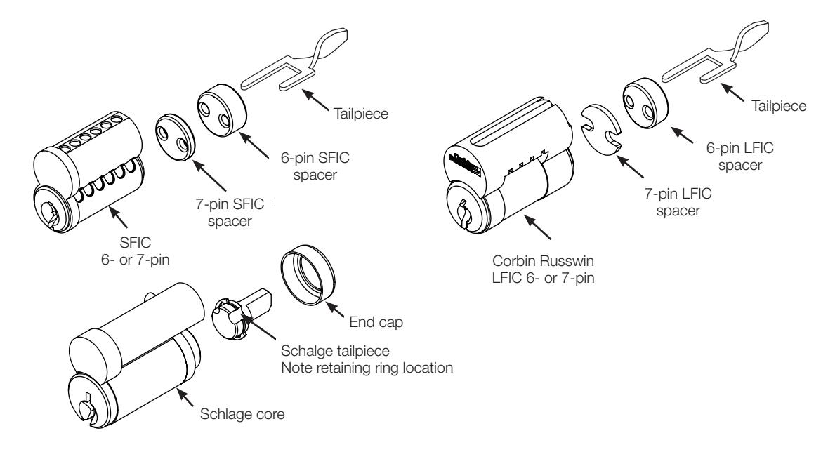
Figure 20 Tailpiece Installation
| Spacer Type | ||||||||
|---|---|---|---|---|---|---|---|---|
| Core Type | Thickness | Color/Material | ||||||
|
6-pin LFIC
Pyramid |
0.197 | Blue/Delrin | ||||||
| 7-pin LFIC | 0.055 | Steel-Zinc Plate | ||||||
| 6-pin SFIC | 0.234 | Black/Delrin | ||||||
| Core Type | 0.093 | Black/Delrin | ||||||
CL3100 Series
Installation Instructions

14
Installation: CL3100 Lever Lock with High Security Lever (M111)
a
Assemble Lock Body
- 1. Prep door and install lock bearing and latch according to door and frame preps that appear on page 3 step 1.
- 2. Complete assembly of lock with security lever attachment according to the following steps.
b
Install Security Attachment Screw
Using screwdriver provided, unscrew the security attachment screw from lever catch on the outside sleeve.
Important
Keep screw for reinstallation.
2. Install outside and inside sleeves and roses according to sleeve installation instruction on page 6 step 6.
Note
The cam in the outside sleeve must be rotated so the large slot is horizontal. This allows the security screw to thread into the cam. See cam orientation, page 7 step 7.
Insert the security attachment screw into lever catch assembly and tighten until screw head is within approximately 1/8" of lever catch. Do not overtighten.
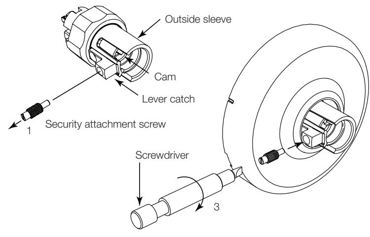
Figure 21 Security Attachment Screw
C
Install Lever
Important
Before installing levers read "Specific Instruction Per Function - Before Installing Lever" on page 6.
- 1. Place cylinder in outside lever. Insert key and rotate 45° clockwise.
- 2. With key rotated, push lever onto sleeve until hole on inside of lever is over security attachment screw. If screw interferes with assembly, check that screw is fully threaded into lever catch.
- 3. Using screwdriver provided, rotate security attachment screw counter clockwise until flush with surface of lever.
- 4. Secure lever with 6 lobe security set screw.
- 5. Rotate key to horizontal and remove.
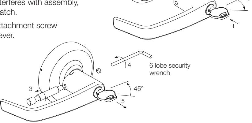
Figure 22 Install Lever
CL3100 Series
Installation Instructions

14
Installation: CL3100 Lever Lock with High Security Lever (cont.)
Remove Cylinder
- 1. Remove security screw on outside of lever with 6 lobe wrench.
- 2. Insert key and rotate key 45° clockwise; keep key in this position.
- 3. Using screwdriver, tighten the security attachment screw clockwise until it clears the lever.
- 4. Remove lever and remove key.
- 5. Remove cylinder from lever and install new cylinder.
- 6. Reinstall lever following steps on previous page.
5. Rosette
4. Rose
Figure 23 Cylinder Removal
15
Dummy Trim Installation
CL3150/70 Half/Full Dummy Trim C, E and K Rose
1. Align mounting plate on both sides of the door with the five (5) holes prepared in the door.
The dimple faces the door edge.
2. Install screw from the opposite side of the door.
Note
Be sure to install mounting plate aligning clearance hole and threaded hole.
- 2A. Install washer and screw from the opposite side of the door (half dummy).
- 3. Install four (4) surface screws (#4 flat head Phillips screws) in the mounting plate.
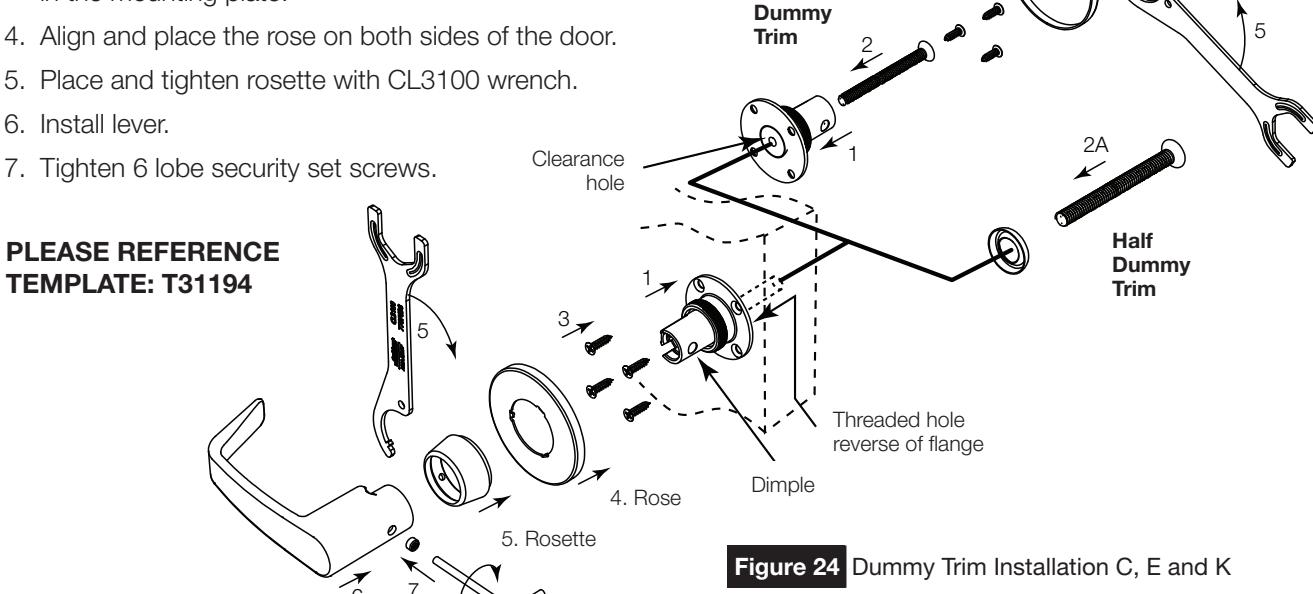
Full
For Installation Assistance contact Corbin Russwin 1-888-607-5703 • techsupport.corbinrusswin@assaabloy.com
CL3100 Series
Installation Instructions

15
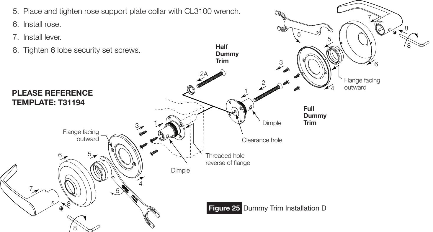
Dummy Trim Installation (cont.)
CL3350/70 Half/Full Dummy Trim D Rose
1. Align mounting plate on both sides of the door with the five (5) holes prepared in the door.
Note
The dimple faces the door edge.
2. Install screw from the opposite side of the door.
Note
Mounting plate with clearance hole and threaded hole.
- 2A. Install washer and screw from the opposite side of the door (half dummy).
- 3. Install four (4) surface screws (#4 flat head Phillips screws) in the mounting plate.
- 4. Align and place the rose support plate on both sides of the door.
Note
The flanges are pointing away from the door.
CL3100 Series
Installation Instructions

Page intentionally left blank.

Corbin Russwin 225 Episcopal Road Berlin, CT 06037 Phone: 800-543-3658 Fax: 800-447-6714 www.corbinrusswin.com