Corbin Russwin Access 800 CL33800 TCAC2 Series Installation Instructions
Open the original PDF document
View PDF

Installation Instructions for CL33800 TCAC2 Series Cylindrical Lockset

FM223 10/18
Please read these instructions carefully to prevent missing important Steps.
Please Note: Improper installations may result in damage to the lock and void the factory warranty.
Important: The accuracy of the door preparation is critical for proper functioning and security of this lock. Misalignment can cause premature wear and a lessening of security.
For installation assistance contact Corbin Russwin Inc., at 1-800-810-WIRE (9473)

Table of Contents
| Page | |
|---|---|
| 1) Warning | 1 |
| 2) General Description/Specifications/Features | 2 |
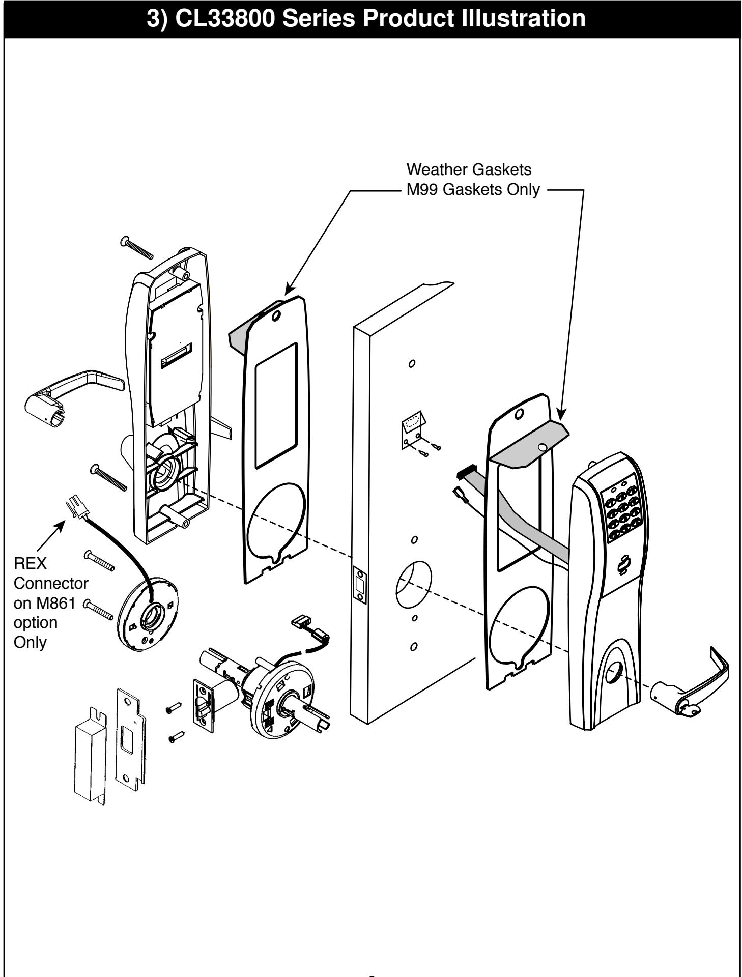
| 3) CL33800 Series Product Illustration | 3 |
| 4) Installation Instructions | 4-9 |
| 5) Installation of RF Technology Lock | 10 |
| 6) Operational Check | 11 |
| 7) Hard Wiring Instructions | 12 |
| 7.1) Important | 12 |
| 7.2) Installation Notes | 12 |
|
7.3) Electro ynx
L ® Connector System |
12 |
| 7.4) M861 Forced Door Propped Door Option | 13 |
| 7.5) M35 Power / Remote 14 Unlocking | 14 |
|
7.6) M35 Power / Remote Unlocking with M861 Forced Door
Propped Door Option |
15 |
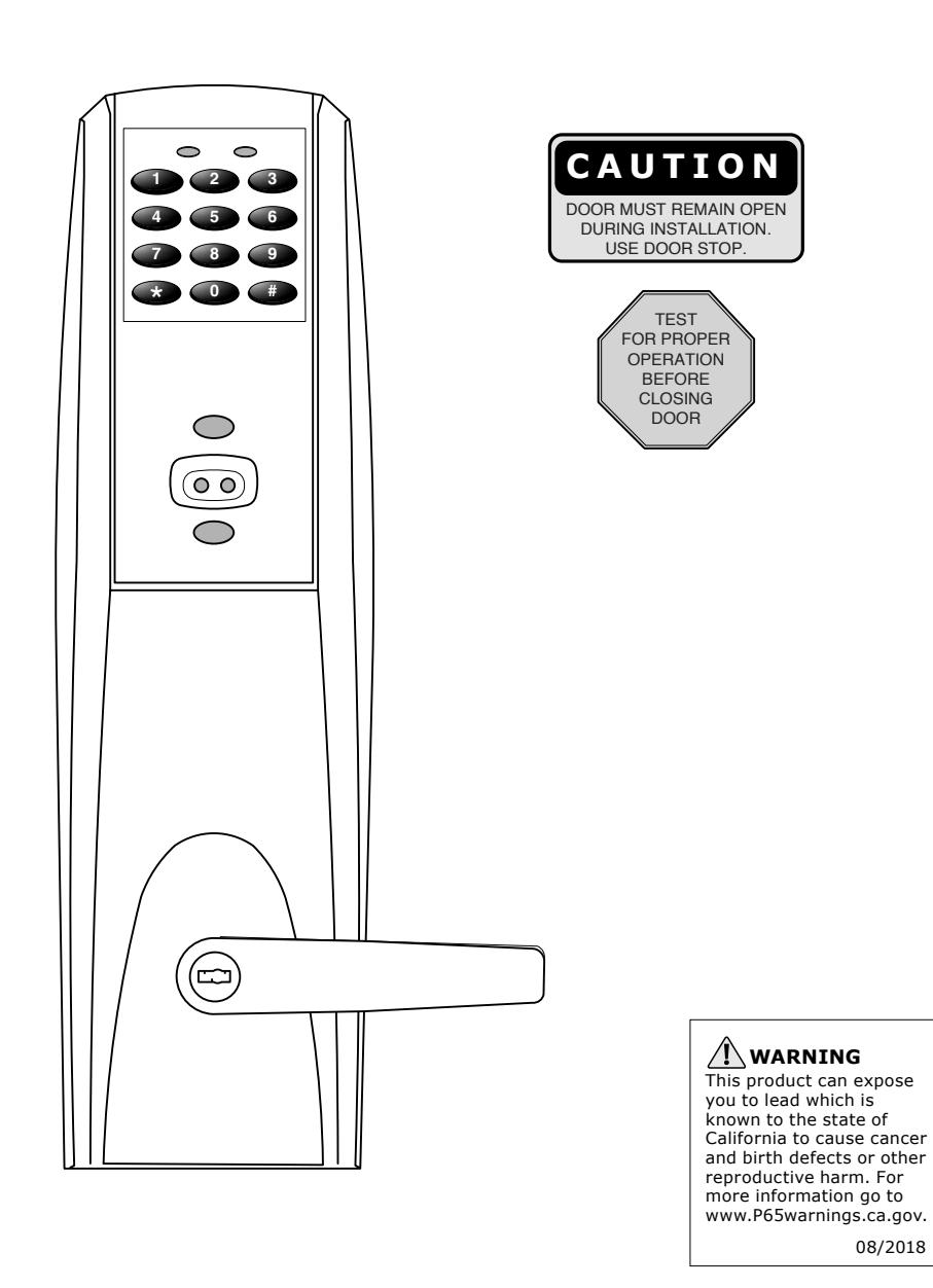
1) Warning
Changes or modifications to this unit not expressly approved by the party responsible for compliance could void the user's authority to operate the equipment.
This device complies with Part 15 of the FCC Rules. Operation is subject to the following two conditions: (1) this device may not cause harmful interference, and (2) this device must accept any interference received, including interference that may cause undesired operation. Note: This equipment has been tested and found to comply with the limits for a Class B digital device, pursuant to Part 15 of the FCC Rules. These limits are designed to provide reasonable protection against harmful interference in a residential installation. This equipment generates, uses and can radiate radio frequency energy and if not installed and used in accordance with the instructions, may cause harmful interference to radio communications. However, there is no guarantee that the interference will not occur in a particular installation. If this equipment does cause harmful interference to radio or television reception, which can be determined by turning the equipment off and on, the user is encouraged to try to correct the interference by one or more of the following measures:
- � � Reorient or relocate the receiving antenna
- � � Increase the separation between the equipment and receiver
- � � Connect the equipment into an outlet on a circuit different from that to which the receiver is connected
- � � Consult the dealer or an experienced TV technician for help
This Class B digital apparatus complies with Canadian ICES-003.
WARNING: To comply with "Fire Listed" doors, only alkaline batteries must be used.

2) General Descriptions/ Specifications/ Features
General Description
The Access 800 Cylindrical Lock is designed for areas which require stand alone authorized entry. It is a self- contained microprocessor-controlled keypad with non-volatile memory. The keypad will hold a total of 100(M800)/2000 (M801, M802, M803, M804, M805, M806) different user codes. User codes "01", "02" and "03" are utilized for Master, Emergency and Supervisory Codes respectively. This product is operated by six (6) "AA" alkaline batteries. Corbin Russwin Inc. locks are designed with quality components to provide high security, performance and durability.
Specifications
- Latch 1/2" standard Inside lever retracts latch 3/4" throw fire rated double doors • Locks furnished for 1-3/4" to 2" doors (optional) (M16- prefix) • U.L. Listed
- Cylinder override
- Outside lever controlled by keypad, or key retracts latch
- Deadlocking latch For 2-1/4" doors specify option D214
Features
- Battery operated with 6 "AA" Alkaline may start with zero
- Low battery alert–4 chirps after standard User Codes disables all codes for a
- External remote "request to enter" connector Yellow LED on solid
- Master, Emergency or Supervisory code will M800 allows last 15 transactions to be unlock door when low battery has expired output to portable printer via infrared link
- Accessware™ with Access HH Software software
- RF Fob and Proximity Card, Tag, Fob are optional
- Non volatile memory Operates utilizing any two to six digits per • Motor driven, locking mechanism code. Digits may be repeated and codes
-
Cylinder override Entry of a programmable number of wrong user code entry programmable number of seconds
- Programming done at the keypad (Except M801 M806 allows last 2000 transactions to M802 & M805) or with a PDA using be output to a PC via a PDA and Accessware


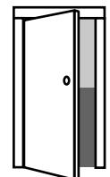
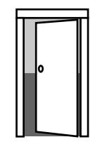
Verify Hand and Bevel of door. Illustrations shown are as viewed from the outside or secure side of opening. 1
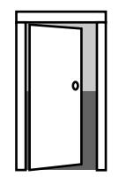
Left Hand Hinges Left. Open Inward. "LH"
Left Hand Reverse Bevel Hinges Left. Open Outward "LHR"
Right Hand Hinges Right. Open Inward. "RH"
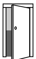
Right Hand Reverse Bevel Hinges Right. Open Outward "RHR"
2 Prep door according to supplied Corbin Russwin Inc. door marker.
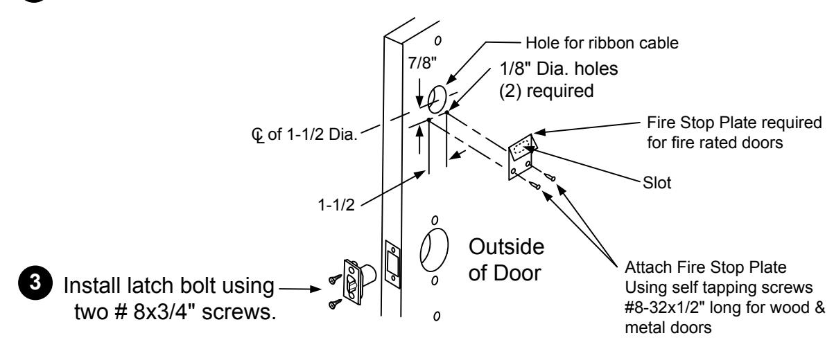
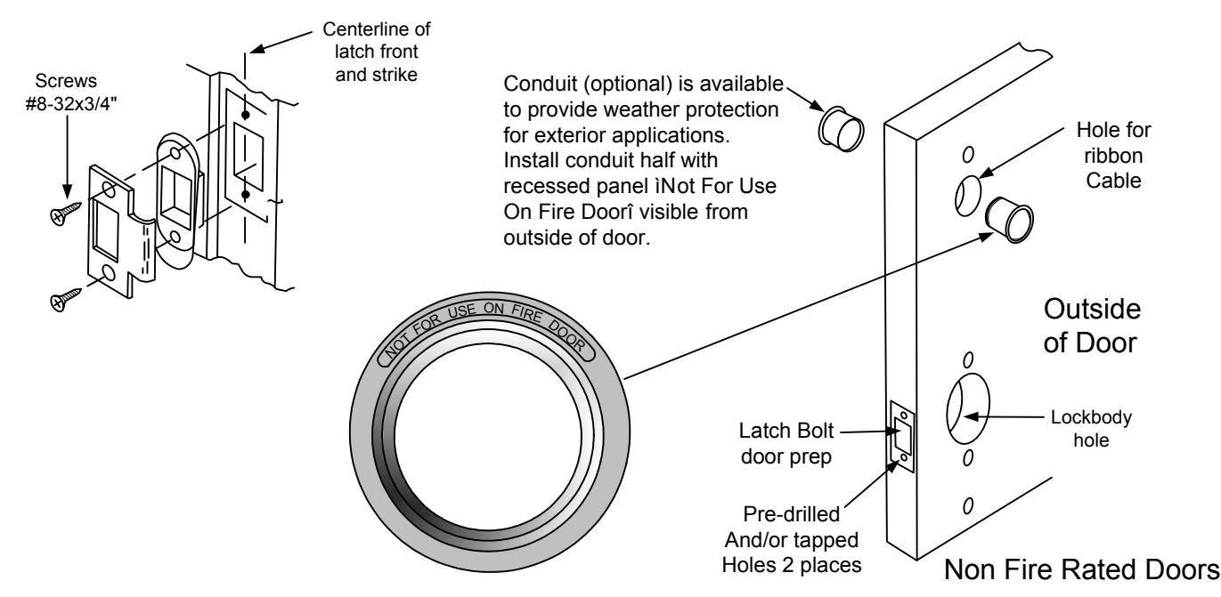
4 Install Strike Plate using two # 8-32x3/4" screws.

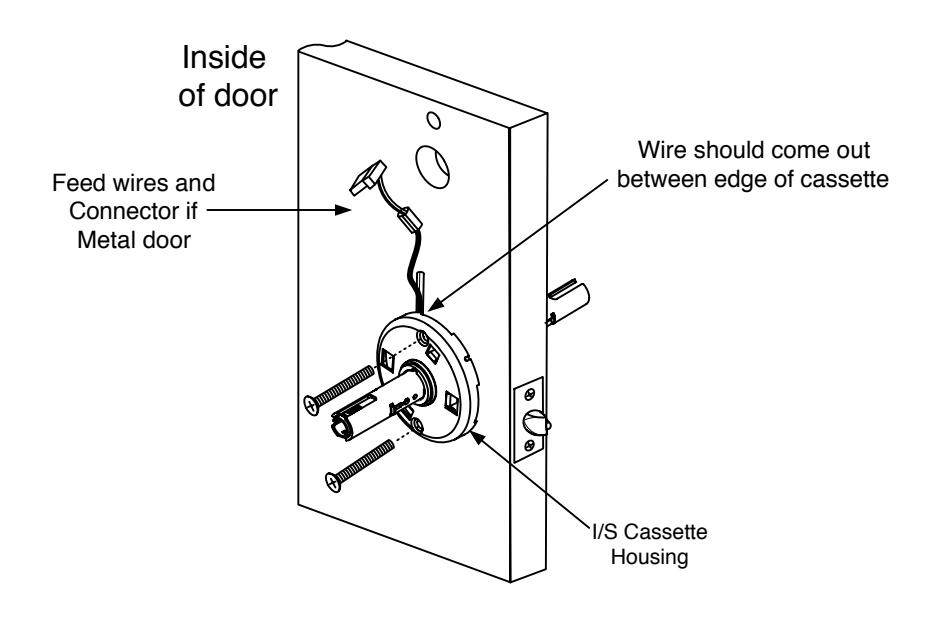
5 Installing chassis to Door
Feed lockbody wire harness through 2-1/8" diameter lockbody hole and then install lockbody into door.
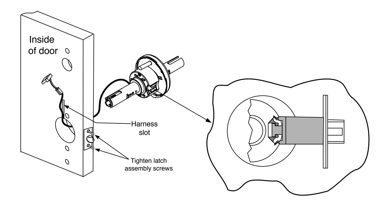
Insure lockbody wire harness is positioned in the vertical slot. Attach inside cassette housing and secure with screws. 6

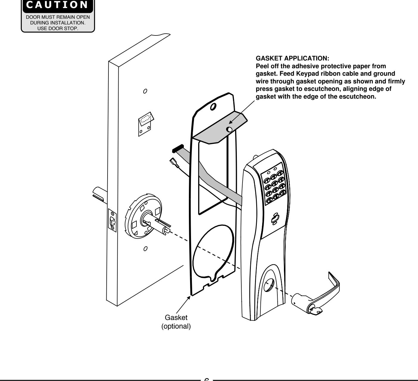
7 Outside Escutcheon Installation
- 1A. For fire rated doors feed ribbon cable connector and ground wire from outside escutcheon through the fire stop plate.
- 1B. For non-fire rated door applications, optional gaskets may be used as a weather seal between the escutcheon and the door surfaces. An optional conduit is also available for further protection. Feed ribbon cable connector and ground through the conduit (if used).
- 2. Slide the outside escutcheon over the lock, and hold the escutcheon to the door surface.

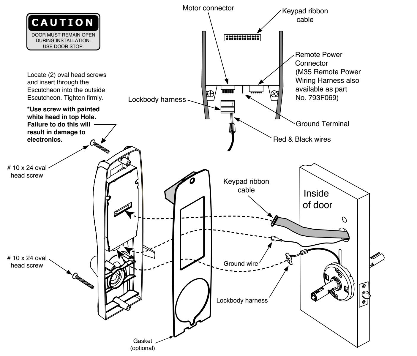
8 Inside Escutcheon installation and Electrical connections
- 1. Remove black battery cover from the escutcheon with High Security T20 Torx bit provided.
- 2. Connect ground wire to terminal, connect keypad ribbon cable to controller, and connect lock body motor harness to motor connector.
- 3. Feed all excess wire through inside door hole and/into outside escutcheon cavity, being careful not to pinch wires.
NOTE: Connectors go on only one way, do not offset connector and be sure they are completely seated.
- 4. Insert 2 #10 x 24 screws through top and bottom of inside escutcheon (use painted screw on top) and thread into outside escutcheon. Straighten escutcheons and tighten securely, being careful to avoid pinching wires.
- 5. Slide the Inside Lever onto the tube.
NOTE: For RF Technology versions refer to Section 5 to install through-bolt screws.

9 Installation and removal of Lever and Standard Cylinder
| LEVER STYLE | REMOVAL | INSTALL |
|---|---|---|
| PLAIN LEVER | PUSH RELEASE TOOL | SLIDE LEVER OVER |
| RELEASE HOLE ASSEMBLY RELEASE TOOL |
Push release tool
Into release hole, Remove lever |
Slide lever over
Lever catch Pull on lever. Make sure lever will not pull off |
| CYLINDER LEVER | ROTATE KEY | INSERT KEY AND ROTATE |
| RELEASE HOLE RELEASE TOOL RELEASE KEY | Rotate key 45 clockwise (from shed position), Push in release tool into Release hole, remove lever | Insert key and rotate 45 (from Shed position), slide lever on Make sure lever will not pull off |
Install Standard Cylinder
Make sure lock is unlocked.
A. Make sure cylinder tailpiece is aligned in same direction as cylinder bible. Slide cylinder all the way into lever.
For 6 pin cylinder: Fold retainer at hinge and press fit retainer halves together as shown. For 7 pin cylinder: Break retainer at hinge and discard spacer section. Also remove black cylinder spacer from inside of chassis rollback for clearance.
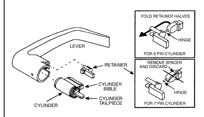
Standard Cylinder Tailpieces
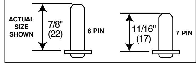
Dimensions are given in inches (mm).

10
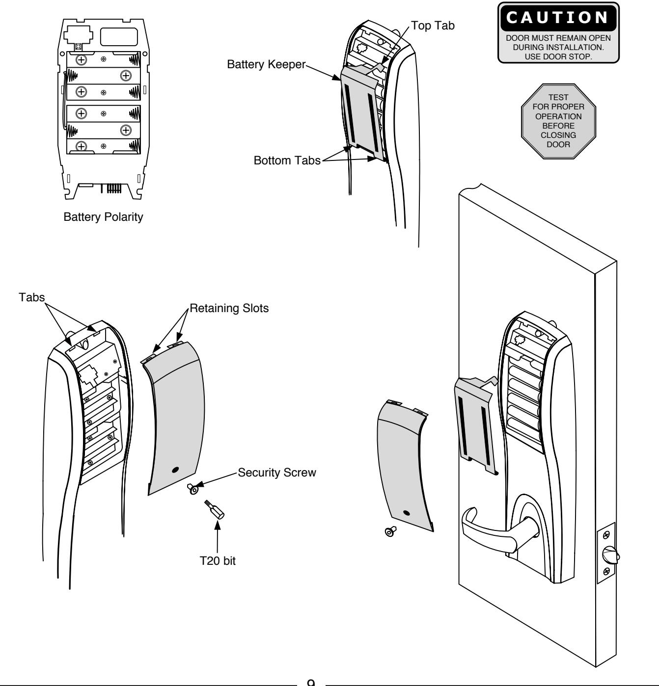
Battery Installation
- 1. Remove battery keeper by lifting top tab and pulling away from the unit.
- 2. Install (6) AA Batteries into controller compartment being careful to align +/- polarity properly.
- 3. Install Battery Keeper by first inserting bottom tabs in bottom slots of controller. Lift the top tab over batteries and snap into position.
- 4. Attach battery cover to inside controller escutcheon making sure to line up tabs with retaining slots in battery cover. Secure with security screw using security bit T20.

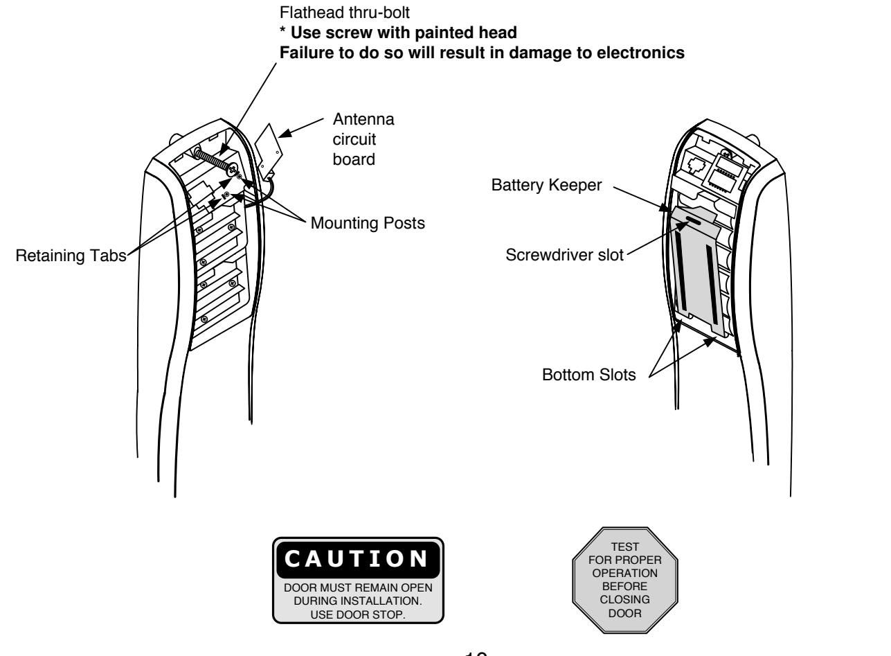
5) Installation of RF Technology Lock
11 The RF Technology Lock (M804, M805, M806) is installed as described in section 4 with the following exceptions:
Installation of the top through-bolt screw Removal procedure for the battery keeper
1. Installation of the top through-bolt screw:
The antenna board must be carefully moved to access the upper through-bolt screw. Care should be taken to prevent damage to the antenna retaining tabs during this process.
Press the two tabs away from the antenna board and lift the board off the mounting posts. Insert the oval head through-bolt and secure the escutcheon in place. After tightening the top through-bolt, replace the antenna board by placing it on the mounting posts and pressing into the retaining tabs.
2 . Removal and Installation Procedure for Battery Keeper
To remove the battery keeper, a flat blade screwdriver or similar tool must be used. Insert screwdriver into slot at top of battery keeper. Lift up and pull the top of the keeper away from the batteries.
To install the battery keeper insert bottom tabs in bottom slots of controller, then press keeper over batteries and snap into position.

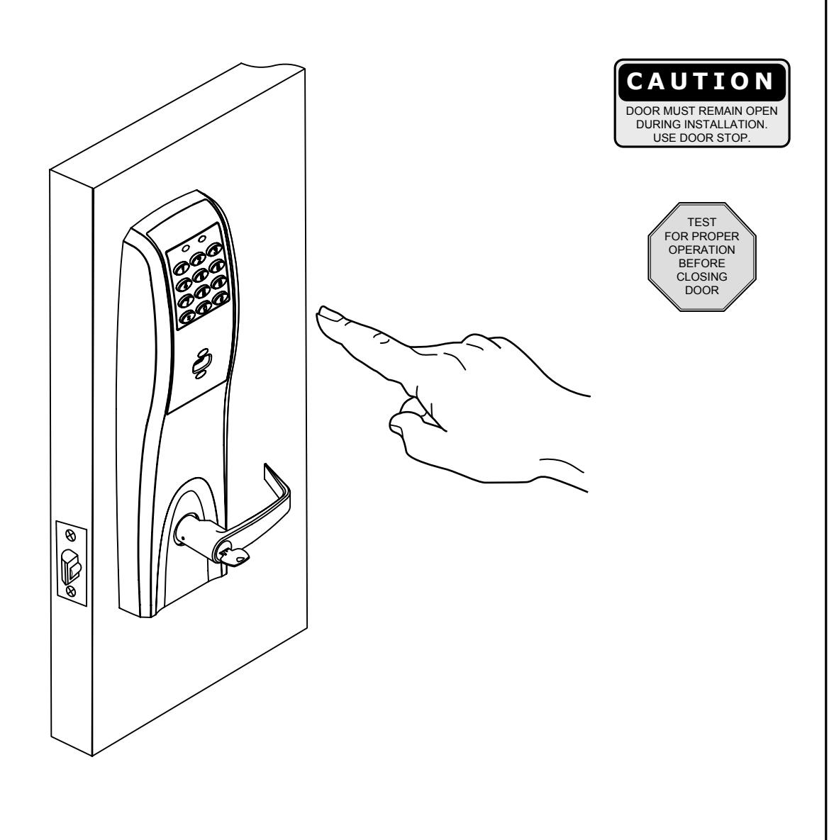
6) Operational Check
-
12 Lock Operational Check For devices with cylinders:
- 1. Insert key into cylinder and rotate.
- 2. The key will retract the latch.
- 3. Enter 1234 to unlock outside lever.
- 4. If lock is prox only (M802) or RF Technology with prox (M805) refer to keypad programming instructions (FM226) to program lock using Accessware software.
7) Hard Wiring Instructions
Hardwiring options include one or a combination of the following: M861 Forced Door Propped Door Option, M35 Power/Remote Unlocking Harness
7.1) Important
- 1. Caution: disconnect all input power before beginning installation to prevent electrical shock and equipment damage.
- 2. Installer must be a trained, experienced service person.
- 3. All wiring must comply with applicable local electrical codes, ordinances and regulations.
7.2) Installation Notes
- 1. With new applications, an ElectroLynx® door harness with 8 and 4 pin connectors will be pre-installed inside door by ASSA ABLOY door manufacturer when specified during ordering process.
- 2. Wiring to pigtail harness is per facility wiring requirement. ElectroLynx® connector terminations and wire colors all match.
- 3. If door does not have an ElectroLynx® type door harness, cut connectors off product and hard wire, or consult factory for appropriate mating harness.
7.3) ElectroLynx® Connector System Notes:
The system is designed to be installation friendly with pluggable connectors from the electric hinge through the door to the rail. The only wiring required is to the loose wires on the pigtail harness assembly on the frame side of the electric hinge.
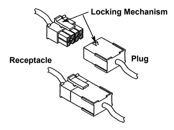
IMPORTANT:
The plug and receptacle connectors are designed to mate and lock together as shown in the figure. Plug the connectors into each other with the locking mechanism aligned as indicated.
Do NOT Force connectors on any other way.

As part of their promise to provide innovative, fast and effective high security solutions to their customers, ASSA ABLOY Group companies offer ElectroLynx®, a universal quick-connect system that simplifies the electrification of the door opening.
ElectroLynx® is a registered trademark of ASSA ABLOY Inc.

7) Hard Wiring Instructions
7.4) M861 Quick Code, Forced Door Propped Door Option.
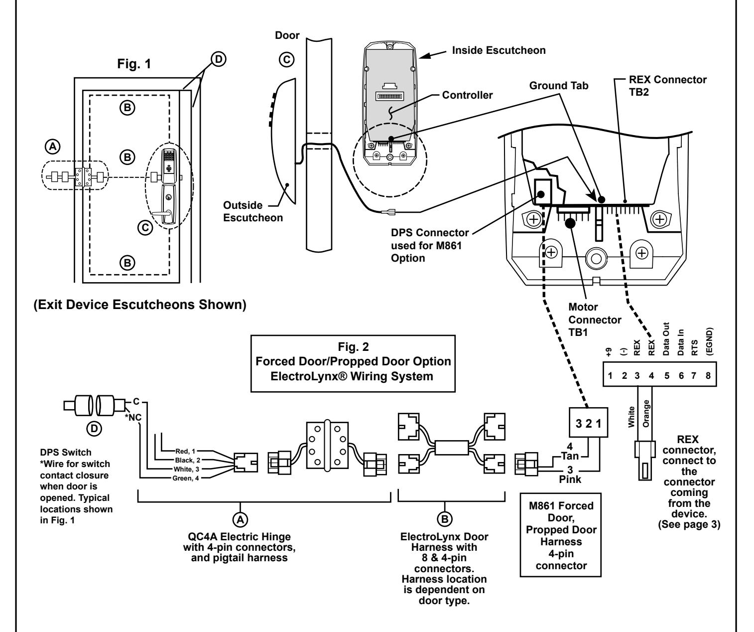
Installation:
-
1. ElectroLynx® System Wiring Instructions (refer to Fig. 1 and Fig. 2)
- a. Look for the mating part on ASSA ABLOY doors and frames. Then plug in all connectors as shown in Fig. 2 during product installation.
- b. Hard wire DPS switch as shown.
-
2. Non-ElectroLynx System Wiring Instructions (refer to Fig. 1 and Fig. 2)
- a. Cut the 4-pin connector off the Forced Door Propped Door harness and hard wire to ElectroLynx® two conductor door harness.
- b. Hard wire door harness to power transfer device.
- c. Hard wire DPS switch to power transfer device.

Hard Wiring Instructions
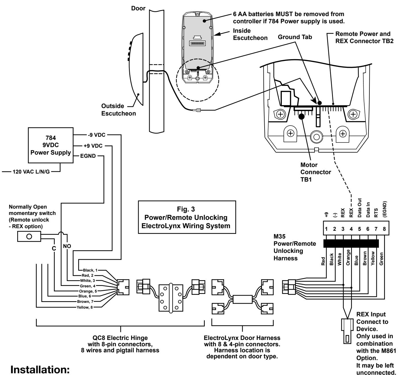
7.5) M35 Power/Remote Unlocking Harness.
-
1. ElectroLynx® System Wiring Instructions (refer to Fig. 1 and Fig. 3)
- a. Look for the mating part on ASSA ABLOY doors and frames. Then plug in all connectors as shown in Fig. 3 during product installation.
- b. Hard wire 784 power supply as shown.
-
2. Non-ElectroLynx System Wiring Instructions (refer to Fig. 1 and Fig. 3)
- a. Cut the 8-pin connector off the Power/Remote Unlocking harness and hard wire to non-ElectroLynx door harness. Remote power requires three conductors and remote unlock requires two conductors.
- b. Hard wire door harness to power transfer device.
- c. Hard wire 784 power supply as shown.
7.6) M35 Power/Remote Unlocking with M861 Propped Door, Forced Door. 1 2 3 4 5 6 7 8 +9 (-) REX REX Data Out Data In RTS (EGND) 784 9VDC Power Supply Fig. 4 Power/Remote Unlocking Forced Door, Propped Door 120 VAC L/N/G EGND +9 VDC -9 VDC 6 AA batteries MUST be removed from controller if 784 Power supply is used. Door Outside Escutcheon Inside Escutcheon Ground Tab Remote Power and REX Connector TB2 Motor Connector TB1 Controller 7) Hard Wiring Instructions Normally Open momentary switch (Remote unlock - REX option)
ElectroLynx Wiring System
Installation:
DPS Switch *Wire for switch contact closure when door is opened. Typical locations shown in Fig. 1
Black, 1 Red, 2 White, 3 Green, 4 Orange, 5 Blue, 6 Brown, 7 Yellow, 8
Red, 1 Black, 2 White, 3 Green, 4
C *NC
C NO
-
1. ElectroLynx® System Wiring Instructions (refer to Fig. 1 and Fig. 4)
- a. Look for the mating part on ASSA ABLOY doors and frames. Then plug in all connectors as shown in Fig. 4 during product installation.
ElectroLynx Door Harness with 8 & 4-pin connectors. Harness location is dependent on door type.
- b. Hard wire forced/propped, hard power and/or remote unlock (REX) as shown.
-
2. Non-ElectroLynx System Wiring Instructions (refer to Fig. 1 and Fig. 4)
- a. Cut the 8-pin connector off the Power/Remote Unlock harness and hard wire to non-ElectroLynx door harness. Remote power requires three conductors and remote unlock requires two conductors.
- b. Hard wire door harness to power transfer device.
QC12 Electric Hinge with 8 and 4-pin connectors, 12 wires and pigtail harness
c. Hard wire forced/propped, hard power and/or remote unlock (REX), as shown.
END OF INSTALLATION INSTRUCTIONS
Red Black White Orange Blue Brown Yellow Green
3 2 1
M35
Power/Remote Unlocking Harness
4 Tan 3 Pink
M861 Forced Door, Propped Door Harness 4-pin connector
REX Input Connect to Device (See page 3)


In U.S.A.: Corbin Russwin, Inc. 225 Episcopal Road Berlin, CT 06037-4004 www.corbinrusswin.com
<u>Technical Product Support</u> Phone: 800-810-WIRE (9473)
In Canada: ASSA ABLOY Door Security Solutions Canada 160 Four Valley Drive Vaughan, Ontario, Canada L4K 4T9 www.assaabloy.ca