Corbin Russwin Access 700 PIP1 and PWI1 Exits Installation Instructions_FM326
Open the original PDF document
View PDFInstallation Instructions
700 ™

ED5000(S)N Series Exit Devices
9700 TCPIP1 & PWI1 Series Trim

This product can expose you to lead which is known to the state of California to cause cancer and birth defects or other reproductive harm. For more information go to www. P65warnings.ca.gov.
AVERTISSEMENT
Ce produit peut vous exposer au plomb qui, dans l'état de la Californie, est reconnu pour causer le cancer, des anomalies congénitales ou d'autres problèmes de reproduction. Pour plus d'informations, visitez: www. P65warnings.ca.gov.
WARNING
Attention Installer: Improper installation may result in damage to the product and void the factory warranty.
For installation assistance contact Corbin Russwin 1-800-543-3658 • techsupport.corbinrusswin@assaabloy.com
Copyright © 2019, 2023, ASSA ABLOY Access and Egress Hardware Group, Inc. All rights reserved. Reproduction in whole or in part without the express written permission of ASSA ABLOY Access and Egress Hardware Group, Inc. is prohibited.
9700 TCPIP1 & PWI1 Series Trim
Installation Instructions

|
Regulatory Compliance 4
Warning 4 General Description 5 Regulatory & Power Specifi cations 5 |
|---|
| 5 |
| Power Supply Specifi cations 5 |
| 6 |
| 6 |
| Electrical Specifi cations 6 |
| 7 |
| Parts Breakdown 7 |
| PIP (PoE) Wiring and Installation 8 |
| Overview - Corbin Russwin ED5000N PIP (PoE) Typical Application 8 |
| 10 |
| PoE Door Harness 11 |
| IN100 Installation Instructions 12 |
| Verify Hand and Bevel of Door 12 |
| Prep Door According to Supplied Door Marker (FM410) 12 |
For installation assistance contact Corbin Russwin
9700 TCPIP1 & PWI1 Series Trim
Installation Instructions

| TOC | Table of Contents, continued |
|---|---|
| c | Trim Assembly Instructions 13 |
| d | Install Rim Exit Device 14 |
| e | Install Head Cover 15 |
| 9 | Mortise Exit Installation Instructions 16 |
| a | Verify Hand and Bevel of Door 16 |
| b | Prep Door According to Supplied Door Marker (FM410) 16 |
| c | Install Mortise Assembly 17 |
| d | Install Exit Device 18 |
| e | Install Head Cover 19 |
| 10 | PIP (PoE) & PWI (WiFi) Installation Instructions 19 |
| a | Install Outside Escutcheon and (optional) Weatherseal Gasket 19 |
| b | Install Outside Escutcheon and Mounting Plate Assembly 20 |
| c | Installation of Connectors 21 |
| d | Installation of Controller22 |
| e | Supplying Power to the Controller 23 |
| f | Inside Cover Installation23 |
| 11 | Operational Check 24 |
| a | Inside Cover Installation24 |
9700 TCPIP1 & PWI1 Series Trim
Installation Instructions


1 Regulatory Compliance
Changes or modifi cations to this unit not expressly approved by the party responsible for compliance could void the user's authority to operate the equipment.
FCC:
This equipment has been tested and found to comply with the limits for a Class B digital device, pursuant to Part 15 of the FCC Rules. These limits are designed to provide reasonable protection against harmful interference in a residential installation. This equipment generates, uses, and can radiate radio frequency energy and, if not installed and used in accordance with the instructions, may cause harmful interference to radio communications. However, there is no guarantee that interference will not occur in a particular installation. If this equipment does cause harmful interference to radio or television reception, which can be determined by turning the equipment off and on, the user is encouraged to try to correct the interference by one or more of the following measures:
- Reorient or relocate the receiving antenna.
- Increase the separation between the equipment and receiver.
- Connect the equipment into an outlet on a circuit different from that to which the receiver is connected.
- Consult the dealer or an experienced radio/TV technician for help.
Industry Canada:
This Class B digital apparatus meets all requirements of the Canadian Interference Causing Equipment Regulations. Operation is subject to the following two conditions: (1) this device may not cause harmful interference, and (2) this device must accept any interference received, including interference that may cause undesired operation.
Cet appareillage numérique de la classe B répond à toutes les exigences de l'interférence canadienne causant des règlements d'équipement. L'opération est sujette aux deux conditions suivantes: (1) ce dispositif peut ne pas causer l'interférence nocive, et (2) ce dispositif doit accepter n'importe quelle interférence reçue, y compris l'interférence qui peut causer l'opération peu désirée.
This equipment complies with FCC radiation exposure limits set forth for an uncontrolled environment. This equipment should be installed and operated with minimum distance 20cm between the radiator and your body. This transmitter must not be co-located or operating in conjunction with any other antenna or transmitter.
Cet équipement est conforme aux limites d'exposition aux radiations de la FCC définies pour un environnement non contrôlé. Cet équipement doit être installé et utilisé à une distance minimale de 20 cm entre le radiateur et votre corps. Cet émetteur ne doit pas être co-localisé ou fonctionner en conjonction avec une autre antenne ou un autre émetteur.
Under Industry Canada regulations, this radio transmitter may only operate using an antenna of a type and maximum (or lesser) gain approved for the transmitter by Industry Canada. To reduce potential radio interference to other users, the antenna type and its gain should be so chosen that the equivalent isotropically radiated power (e.i.r.p.) is not more than that necessary for successful communication.
Conformément à la réglementation d'Industrie Canada, le présent émetteur radio peut fonctionner avec une antenne d'un type et d'un gain maximal (ou inférieur) approuvé pour l'émetteur par Industrie Canada. Dans le but de réduire les risques de brouillage radioélectrique à l'intention des autres utilisateurs, il faut choisir le type d'antenne et son gain de sorte que la puissance isotrope rayonnée équivalente (p.i.r.e.) ne dépasse pas l'intensité nécessaire à l'établissement d'une communication satisfaisante.
2 Warning

- Please read these instructions carefully to prevent missing important steps.
- Please Note: Improper installations may result in damage to the lock and void the factory warranty.
- Important: The accuracy of the door preparation is critical for proper functioning and security of this lock.
- Misalignment can cause premature wear and a lessening of security.

This product can expose you to lead which is known to the state of California to cause cancer and birth defects or other reproductive harm. For more information go to: www.P65warnings.ca.gov.
Ce produit peut vous exposer au plomb qui, dans l'état de la Californie, est reconnu pour causer le cancer, des anomalies congénitales ou d'autres problèmes de reproduction.
Pour plus d'informations, visitez: www.P65warnings.ca.gov.

Any retrofit or other field modification to a fire rated opening can potentially impact the fire rating of the opening, and Corbin Russwin makes no representations or warranties concerning what such impact may be in any specific situation. When retrofitting any portion of an existing fire rated opening, or specifying and installing a new fire-rated opening, please consult with a code specialist or local code official (Authority Having Jurisdiction) to ensure compliance with all applicable codes and ratings.

To avoid possible damage from electrostatic discharge (ESD), some basic precautions should be used when handling electronic components:
- Minimize build-up of static by touching and/or maintaining contact with unpainted metal surfaces such as door hinges, latches, and mounting plates especially when mounting electronic components such as readers and controllers onto the door.
- Leave components (reader and controller) protected in their respective anti-static bags until ready for installation
- Do not touch pins, leads or solder connections on the circuit boards
9700 TCPIP1 & PWI1 Series Trim
Installation Instructions


3 General Description
Designed specifically for the campus market, the Corbin Russwin Access 700 PoE and WiFi locks offer simultaneous support for multiple industry-leading credentials and support HID Mobile Access® powered by Seos®.
Ideal for mixed credential environments, these locks enable an easy, cost-effective transition from magnetic stripe credentials to smart cards and mobile access. Using the facility's Ethernet network, the Access 700 PIP1 Power over Ethernet (PoE) provides full online access control with standard network cabling and minimizes energy consumption, while the Access 700 PWI1 WiFi lock uses 802.11b/g/n infrastructure to significantly reduce hardware and labor costs.

4 Regulatory and Power Specifi cations

a Electronic Authentication Specifi cations (Mobile Credentials)
For Mobile Credential-Enabled versions of this electronic lock (indicated by "BIPS" in the product order string):
- Mobile Credentials are transmitted to the lock via Bluetooth Smart or NFC ISO/IEC14443 and must use a mobile device enabled with these technologies.
- Credential and mobile device versions are specified by the credential provider.
- User must acquire the latest HID "Mobile Access" application available from Apple iStore or Android PlayStore.
- This product is not intended for outside wiring as covered by Article 800 in the National Electrical Code, NFPA 70.
- Compliance with IEEE 802.3 (at or af) specifications was not verified as part of UL294/B.

The system shall not be installed in the fail-secure mode unless permitted by the local authority having jurisdiction and shall not interfere with the operation of Listed panic hardware.
- UL Listed** UL 294 Indoor Use
- CUL Listed S319: Class 1

b Power Supply Specifi cations
PIP (PoE version)
-
Power over Ethernet
- Use UL294 Listed, PoE Injector or Class 2 power limited power supply (55VDC, 90mA).
PWI (WiFi version)
-
Battery Power
- Alkaline AA Batteries (6): 9V, 300mA

To comply with "Fire Listed" doors, batteries must be replaced with alkaline batteries only.
-
Optional Hard Power (UL294 Listed Power Supply Required)
- 9-24VDC, 300mA
Note: Wiring methods shall be in accordance with the National Electrical Code (ANSI/NFPA70), CSA 22.1, Canadian Electrical Code (CEC), Part I, Safety Standard for Electrical Installations, local codes and the authorities having jurisdiction.
UL 294 Access Control Ratings
Destructive Attack Level 1 Line Security Level 1 Endurance Level 4 Standby Power Level 1
9700 TCPIP1 & PWI1 Series Trim
Installation Instructions


5 Specifi cations / Features

a Hardware Specifi cations
- Latch Stainless steel, 3/4" (19mm) throw deadlocking fire latch
- Deadlocking latch prevents manipulation when door closed
- Door Thickness 1-3/4" (44mm) to 2" (50mm) Standard Optional 2" (50mm) to 2-1/4" (57mm) optional
- Outside lever controlled by any combination of keypad, magnetic swipe, iCLASS reader, or mechanical key
- Complete locksets with on-board memory
- ADA Compliant
- Easily retrofits existing Access 700 door preps (exit devices)
- ANSI/BHMA A156.25 Listed Grade 1 Compliant

b Electrical Specifi cations
HID® multiCLASS SE® technology offers support for the following credentials:
- 2.4 GHz credential compatibility:
-
Secure Identity Object™ (SIO) on Mobile IDs (Bluetooth Smart)
- 13.56 MHz credential compatibility:
- iCLASS®
- -iCLASS SE ® (SIO-enabled)
- iCLASS Seos ®
- SIO on MIFARE ® Classic
- -SIO on MIFARE® DESfire® EV1
- MIFARE® Classic
- -DESfire® EV1
-
-NFC-enabled mobile phones
- 125 kHz credential compatibilty:
-
-HID Prox®
- Magnetic Stripe
- -10,000 users per lock; 30,000 event audit trail*
- Multiple time zone and holiday access scheduling
- First-In unlock configuration, based on specified time schedule
- Uses existing Magstripe keycards (track 2)
- -Magnetic Stripe Card Coercivity: HiCo (4000 Oersted) or LoCo (300 Oersted)
* As supported by your OEM provider
9700 TCPIP1 & PWI1 Series Trim
Installation Instructions

6 Product Illustrations
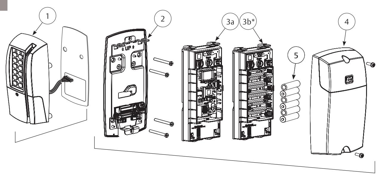
a Parts Breakdown
| Item | Description | ||
|---|---|---|---|
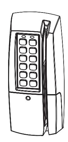
| 1 | Outside Escutcheon Assembly | ||
| 1a | (Optional) Gasket | ||
| 2 | Inside Mounting Plate Assembly (includes Gasket) | ||
| 3a | PoE Controller Assembly | ||
| 3b | WiFi Controller Assembly* (batteries included) | ||
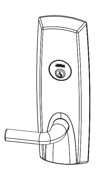
| 4 | Inside Escutcheon Assembly with Privacy Button | ||
| 5 | AA alkaline batteries (6) | ||
| *Bluetooth® Smart option | |||
-
Tools Required:
- a. #2 & #3 Phillips Screw Driver
- b. Flat Blade Screw Driver (Standard size)
- c. 1/8" Security Allen Wrench1/8" Allen Wrench
- d. 7/64" Allen Wrench
- e. T20 Security Torx Driver
9700 TCPIP1 & PWI1 Series Trim
Installation Instructions

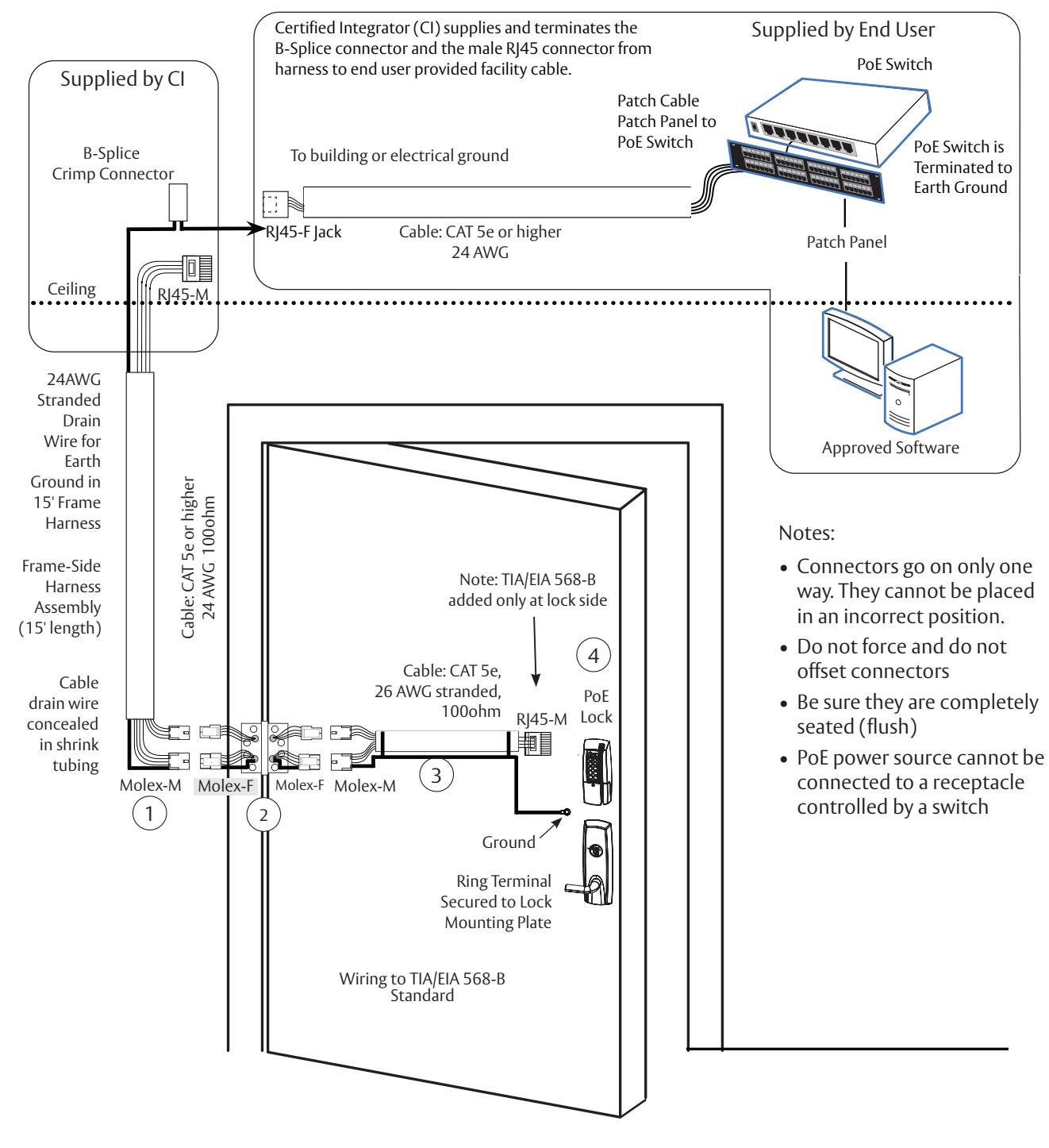
7 PIP (PoE) Wiring and Installation
a Overview - Corbin Russwin ED5000N PIP (PoE) Typical Application
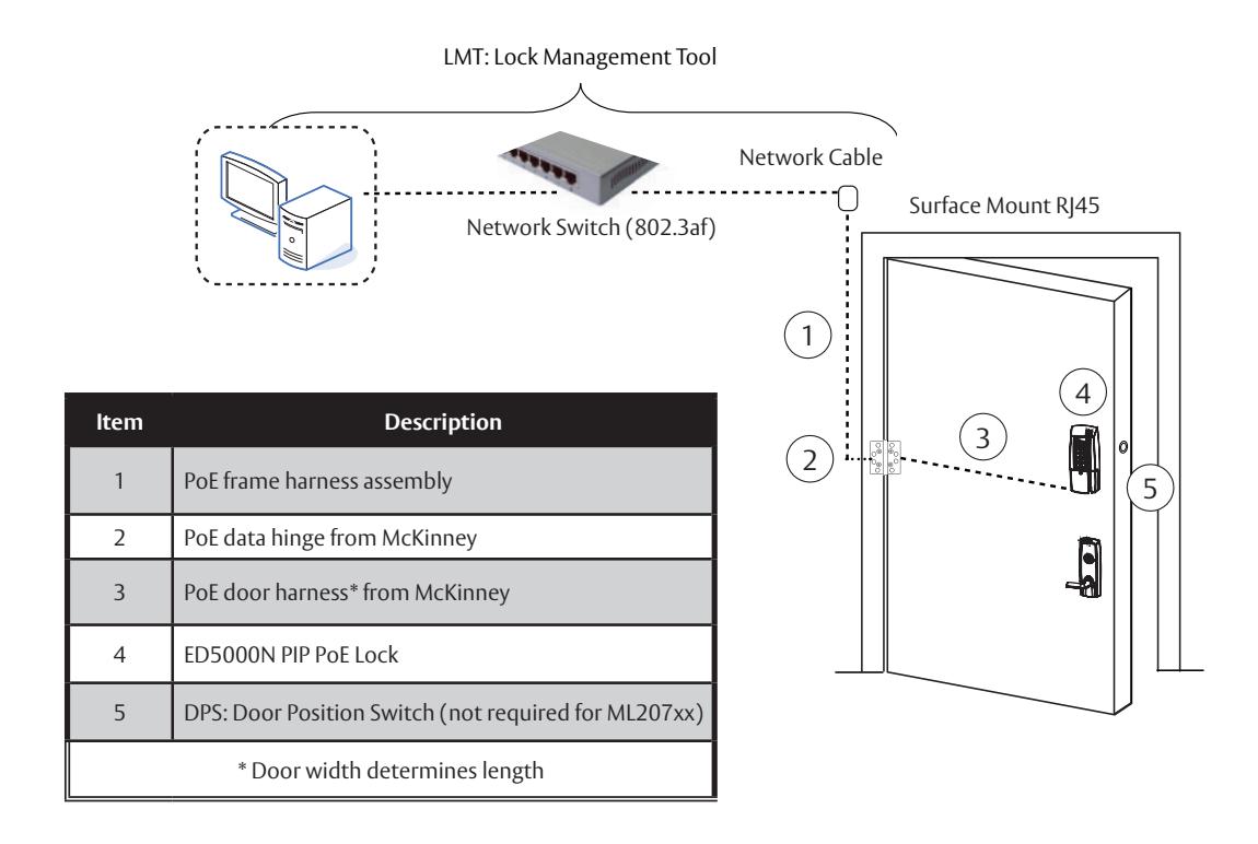
9700 TCPIP1 & PWI1 Series Trim
Installation Instructions

7 PIP (PoE) Wiring and Installation, continued
9700 TCPIP1 & PWI1 Series Trim
Installation Instructions


7 PIP (PoE) Wiring and Installation, continued
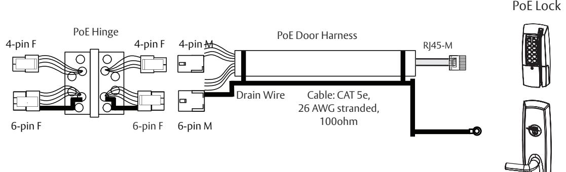
b Frame Harness Installation
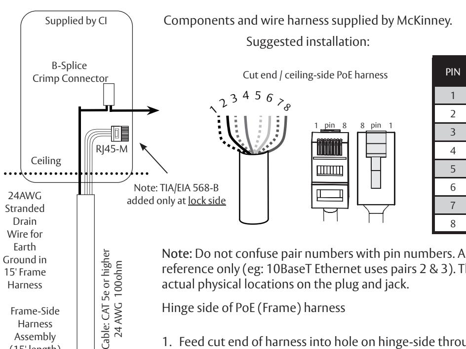
| PIN | Wire |
Pair
Number |
|---|---|---|
| 1 | White/Orange | 2 |
| 2 | Orange | 2 |
| 3 | White/Green | 3 |
| 4 | Blue | 1 |
| 5 | White/Blue | 1 |
| 6 | Green | 3 |
| 7 | White/Brown | 4 |
| 8 | Brown | 4 |
Note: Do not confuse pair numbers with pin numbers. A pair number is used for reference only (eg: 10BaseT Ethernet uses pairs 2 & 3). The pin numbers indicate actual physical locations on the plug and jack.
Hinge side of PoE (Frame) harness
- 1. Feed cut end of harness into hole on hinge-side through single access hole.
- 2. Push one connector back through the hole and feed into the other access hole.
- 3. Each of the hinge-side harness connectors should end up threaded through a different access hole and matched to the same size pin connector from the door harness:
- 4. 4-pin male molex connector
- 5. 6-pin male molex connector with ground wire

Frame-Side Harness Assembly (15' length)
Cable drain wire concealed in shrink tubing
Harness
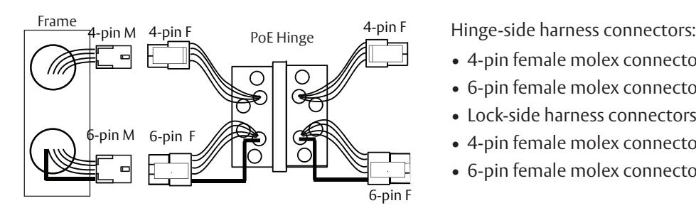
- 4-pin female molex connector
- 6-pin female molex connector with ground wire
- Lock-side harness connectors:
- 4-pin female molex connector
- 6-pin female molex connector with ground wire
FM326 3/23
Molex-M
9700 TCPIP1 & PWI1 Series Trim
Installation Instructions


7 PIP (PoE) Wiring and Installation, continued

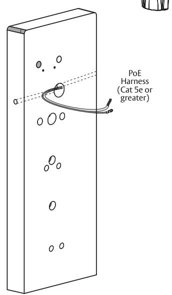
c PoE Door Harness
Note: Order of installation may vary. Refer to appropriate sections for instructions.
Hinge-side harness connectors:
4-pin male Molex connector
6-pin male Molex connector with ground wire
Lock-side harness connectors:
Ring terminal
Male RJ45 connector (crimped after cable is fed through door)
Notes:
Connectors go on only one way. They cannot be plugged to incorrect position.
Do not force and do not offset connectors.
Be sure they are completely seated (flush).
PoE Lock
Order of installation may vary. Refer to appropriate sections for instructions.
- 1. Prop door open.
- 2. Using the ring terminal, carefully route the assembly through the door channel toward lock.

*Do not terminate PoE harness (with RJ45 M) until cable has been routed through door and inside mounting plate assembly. See Section 9, C - "Installing the Connectors."
9700 TCPIP1 & PWI1 Series Trim
Installation Instructions

8 Rim Exit Installation Instructions

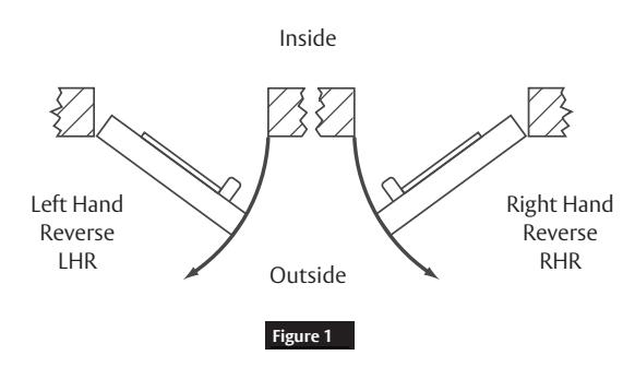
a Verify Hand and Bevel of Door
Door should be fitted and hung. Verify box label for size of exit device, function and hand.
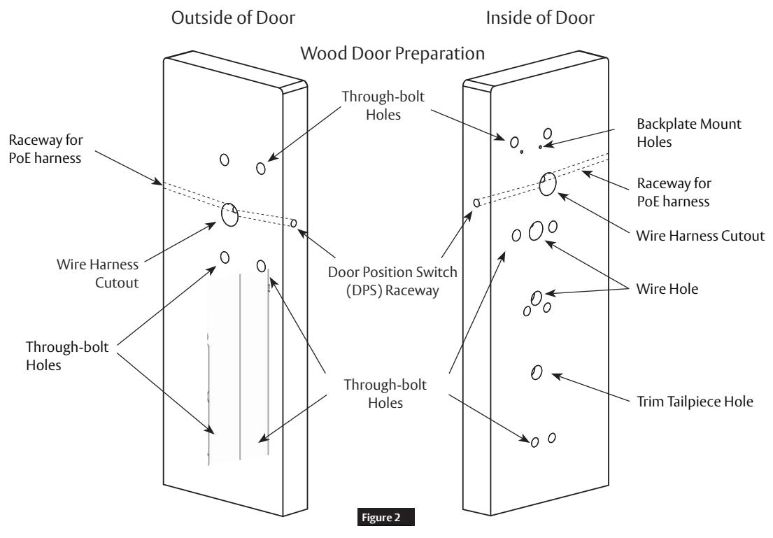
b Prep Door According to Supplied Door Marker (FM410)
Note: For door manufacturer templates visit www.corbinrusswin.com and reference template #'s T31169 & T31170.
9700 TCPIP1 & PWI1 Series Trim
Installation Instructions

8 Rim Exit Installation Instructions, continued

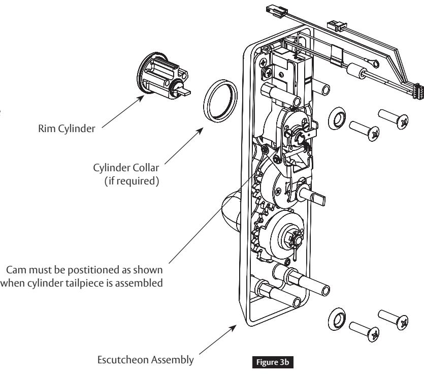
c Trim Assembly Instructions
1. Check cylinder components
Notes:
- Cylinders longer than 1-1/8" (29mm) require collars.
- Refer to Cylinder Collar Chart. (Figure 3a)
- For Mortise, skip to Step 8.
- 2. If required, modify by cutting cylinder tailpiece.
Note: Correct length is 1/16" to 3/16" (2 to 5mm) beyond cylinder housing cam.
-
3. Assemble cylinder.
- a. Insert cylinder housing prongs into matching notches of escutcheon.
- b. Pass cylinder tailpiece through cylinder collar (if required) and slot in cylinder cam.
- c. Fasten cylinder in escutcheon recess or collar using 2 mounting screws.
Note: Do not overtighten screws.
d. Escutcheon Assembly (Figure 3b)
Notes:
- The lever is handed (LHR shown).
- The Lever Return Spring handing can be identified by the color of the spring.
- LHR: Part Number 651F618 (Red)
- RHR: Part Number 651F628 (Blue)
| Cylinder Collar Chart | |||||
|---|---|---|---|---|---|
| Cylinder Length | Collar | ||||
| Inches | Millimeters | ||||
| 1-1/8" | 29mm | None | |||
| 1-1/4" | 32mm | 422F88* | |||
| 1-1/2" | 38mm | 686F98* | |||
| *Specify Finish | |||||
Figure 3 a
9700 TCPIP1 & PWI1 Series Trim
Installation Instructions


8 Rim Exit Installation Instructions, continued

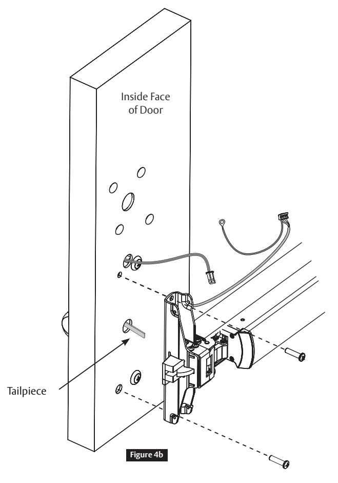
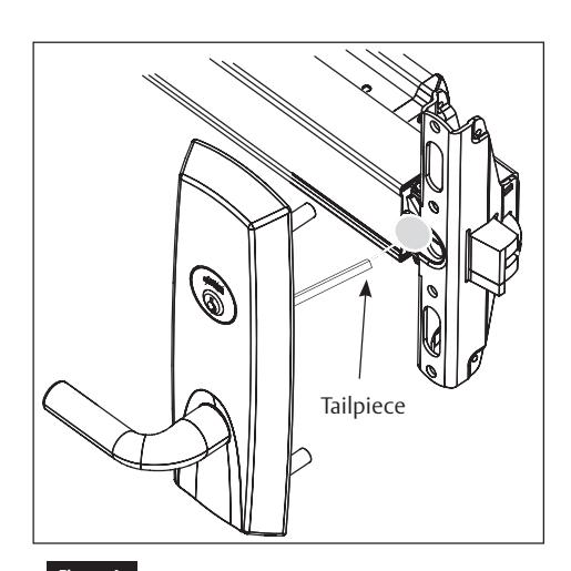
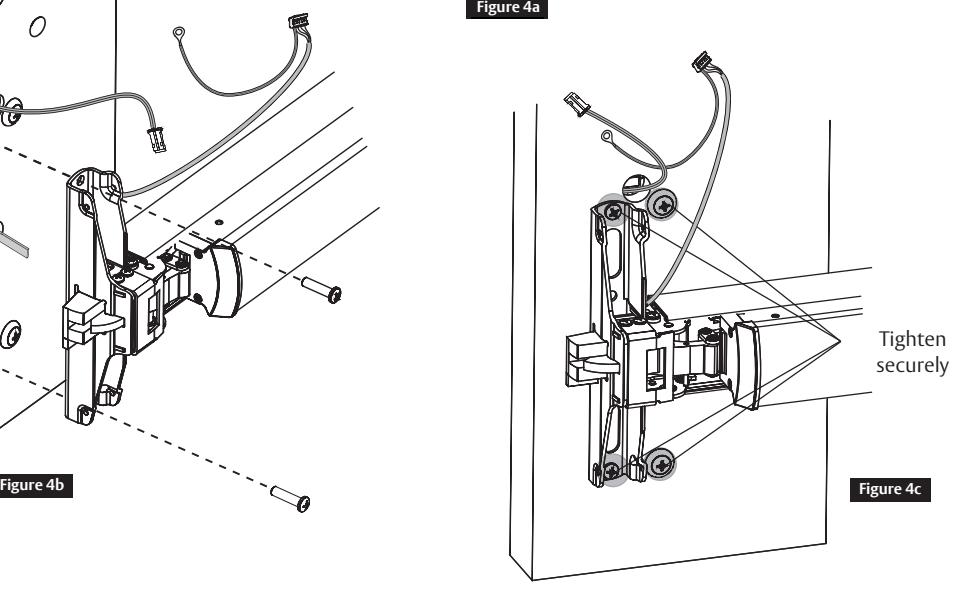
d Install Rim Exit Device
- 1. Seat device against door being careful to align vertical trim tailpiece to engage with cross hole of device cam. (Figure 4a)
- 2. Fasten device to trim assembly using (2) 1/4-20 pan head screws. (Figure 4b)
- 3. Follow instructions packed with device to secure device to door.
- 4. Tighten all (4) screws. (Figure 4c)

When installing trim, pull wires completely through door to avoid contacting motor assembly, as this may cause loss of function.
9700 TCPIP1 & PWI1 Series Trim
Installation Instructions


8 Rim Exit Installation Instructions, continued

e Install Head Cover
- 1. Lay device wire harnesses across ¾" hole. (Figure 5a)
- 2. Fold excess wires next to latch assembly. Note: Avoid feeding excess wires back through the door as they may interfere with trim operation.
- 3. Attach head cover using (2) #8-32 flat head screws. (Figure 5b) Note: Take care not to pinch wires between cover and door.
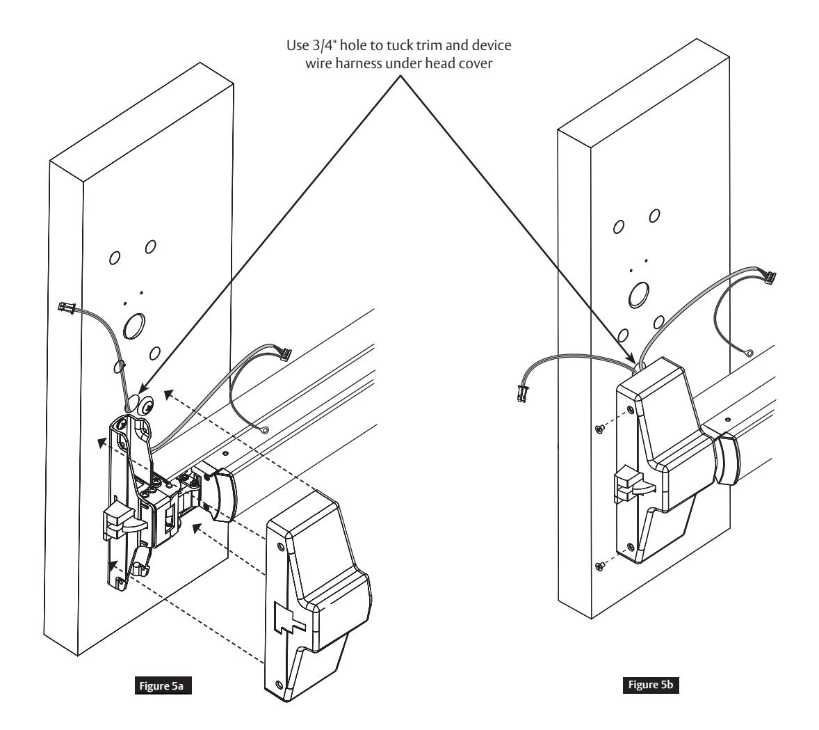
Note: To Complete Rim Exit Installation Proceed to Section 9, "PIP (PoE) & PWI (WiFi) Installation."
9700 TCPIP1 & PWI1 Series Trim
Installation Instructions

9 Mortise Exit Installation Instructions
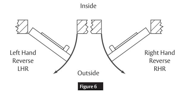
a Verify Hand and Bevel of Door
Note: Door should be fitted and hung.
1. Verify box label for size of exit device, function and hand.
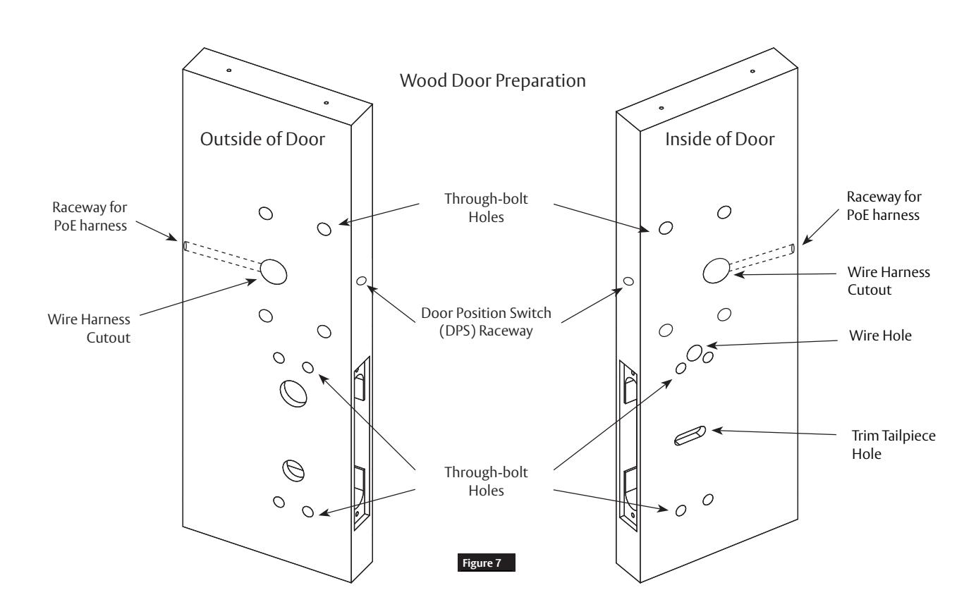
b Prep Door According to Supplied Door Marker (FM410)
Note: For door manufacturer templates visit www.corbinrusswin.com and reference template #'s T31169 & T31170.
9700 TCPIP1 & PWI1 Series Trim
Installation Instructions


9 Mortise Exit Installation Instructions, continued

c Install Mortise and Outside Trim Assembly
- 1. Ensure tailpiece is oriented vertically.
- 2. Feed trim wire harness through wire harness hole. (Figure 8a)
- 3. Mount trim assembly to door pulling slack wire towards device side of door. Note: Be careful not to pinch wire harness.
- 4. When mounting trim, lift tailpiece to pass through hole on device side. (Figure 8b) Note: Ensure tailpiece is still oriented vertically.
5. Fasten trim assembly to door using (2) 1/4-20 oval head screws and (2) finish washers. (Figure 8b) Note: Finger tighten only. Figure 8a Figure 8b
9700 TCPIP1 & PWI1 Series Trim
Installation Instructions


9 Mortise Exit Installation Instructions, continued

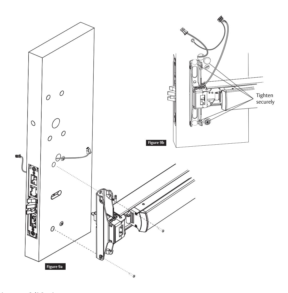
d Install Exit Device
- 1. Seat device against door being careful to align vertical trim tailpiece to engage with cross hole of device cam. (Figure 9a)
- 2. Fasten device to trim assembly using (2) 1/4-20 pan head screws. (Figure 9a)
- 3. Follow instructions packed with device to secure device to door.
- 4. Tighten all (4) screws. (Figure 9b)
9700 TCPIP1 & PWI1 Series Trim
Installation Instructions


9 Mortise Exit Installation Instructions, continued

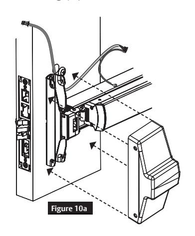
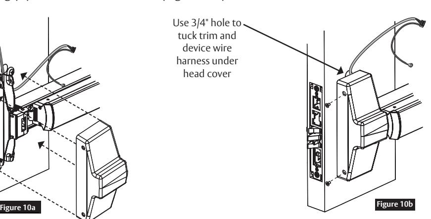
e Install Head Cover
- 1. Lay device wire harnesses across ¾" hole. (Figure10a)
- 2. Tuck wires into hole when installing cover so that wires are not pinched between head cover and door.
- 3. Attach head cover using (2) #8-32 flat head screws. (Figure10b)
10 PIP (PoE) & PWI (WiFi) Installation Instructions

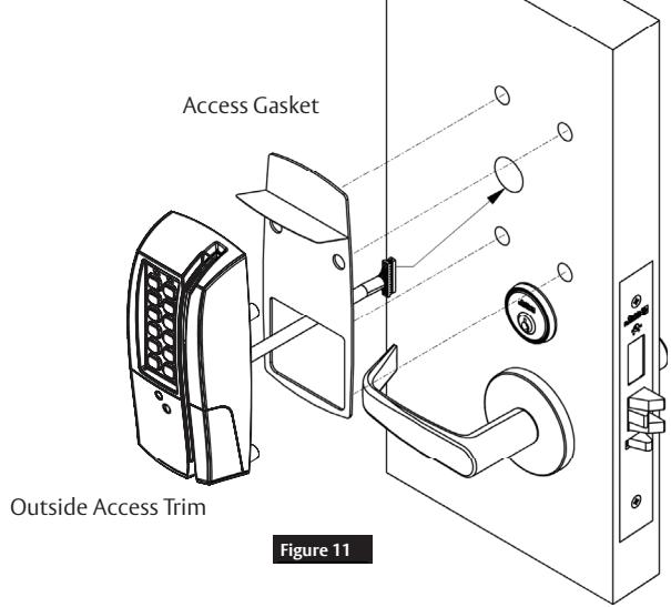
a Install Outside Escutcheon and (optional) Weatherseal Gasket
Notes:
Outside gasket is optional, for non-fire rated doors only. For non-fire rated door applications, a gasket (Part number 52-0782) may be used as a weather seal between the escutcheon and the outside door surface.
- 1. Peel off adhesive backing and attach to outside escutcheon.
- 2. Insert the mounting posts through holes, as shown.
- 3. Feed reader cable through opening. (Figure11)
9700 TCPIP1 & PWI1 Series Trim
Installation Instructions

10 PIP (PoE) & PWI (WiFi) Installation Instructions, continued

b Install Outside Escutcheon and Mounting Plate Assembly
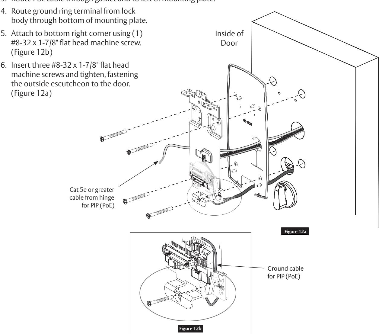
- 1. On the inside of the door, position the mounting plate with gasket over the indicated holes.
- 2. Feed reader cable and ground ring terminal through central opening on mounting plate. (Figure 12a)
- 3. Route PoE cable through gasket and to left of mounting plate.
9700 TCPIP1 & PWI1 Series Trim
Installation Instructions

10
PIP (PoE) & PWI (WiFi) Installation Instructions, continued

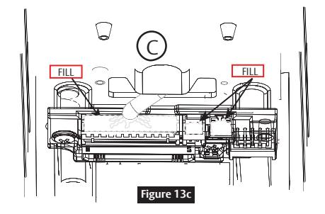
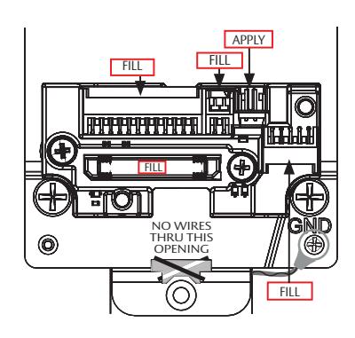
Installation of Connectors

- Do not allow debris to enter connector contacts
- Ensure connectors are covered with silicone dielectric compound (grease)*

- 1. Snip end of packet to dispense grease
- 2. Apply grease, ensuring all connector pins and contacts (Figure 13a) are covered.
Note: Do not overfill or over-apply**
- * Supplied tube contains 5 grams of silicone dielectric compound (grease)
- ** Evenly distribute grease, wiping away excess; full application requires approximately 2.5 grams

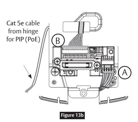
Do not run wires through bottom hole in plate. (Figure 13a, b) - It will damage wires and the controller connector. Route wires around flange, do not route wires through the flange hole. (Figure. 13b)
Secure the following connectors. (Figure 13b, c)
1. Secure the 10-pin lock body assembly connector.
Secure Mounting Plate
- a. Tuck excess cable into wire hole on inside of door.
- b. Secure the mounting assembly while ensuring proper alignment of outside reader.
- c. Fully tighten the (4) through-bolts on the inside of the door to secure the reader and plate to the door.
- 2. Secure the 24-pin card reader connector. (Figure 13b, c)
- 3. Ensure all openings on back of secured reader connector are covered completely with grease. (Figure 13c)

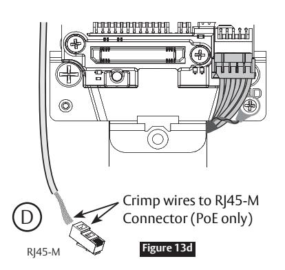
- 4. Crimp** RJ45 to cat5e cable from hinge (Fig. 3d).
- **For more detail, refer to Section 6, "PIP (PoE) Wiring and Installation."

FM326 3/23
Experience a safer and more open world
9700 TCPIP1 & PWI1 Series Trim
Installation Instructions

10 PIP (PoE) & PWI (WiFi) Installation Instructions, continued

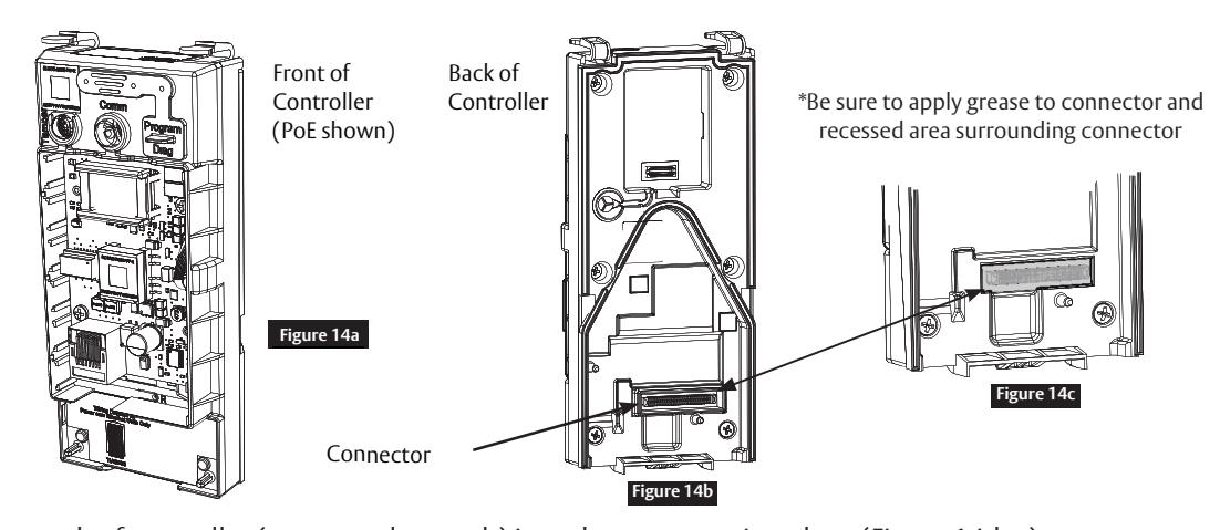
d Installation of Controller
Warning: Before you install the controller:
• Apply dielectric grease to connector* located on back of Controller. (Figure 14b)

Do not allow debris to enter connector contacts.Ensure connectors are covered with silicone dielectric compound (grease)*
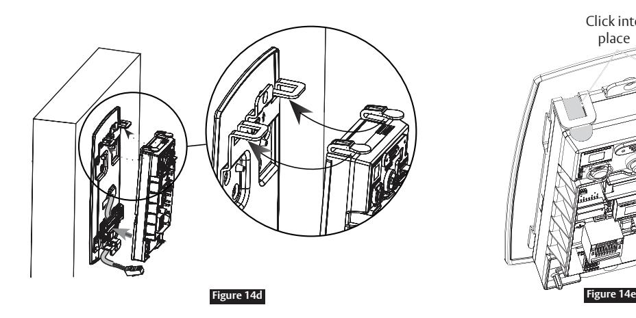
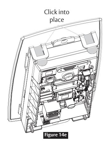
- 1. Insert bottom tab of controller (ensure a clear path) into slot on mounting plate. (Figure 14d, e)
- 2. Ensure proper alignment of board-to-board connectors (Figure 14d) while pivoting controller toward door until two tabs on top click securely into place on mounting plate. (Figure. 14e)

To avoid possible damage to board-to-board connectors, care should be taken when securing controller to mounting plate. If there is resistance when securing, detach controller to determine cause before re-attaching controller.
9700 TCPIP1 & PWI1 Series Trim
Installation Instructions

10 PIP (PoE) & PWI (WiFi) Installation Instructions, continued

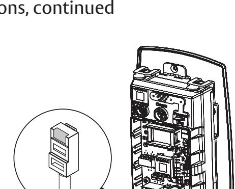
e Supplying Power to the Controller

Before inserting PoE plug into PoE connector, apply dielectric grease to top of plug, covering the pin area (Figure 15a).
PIP (PoE)
- 1. Once controller is securely in place, connect RJ45 male connector to female RJ45 port on controller board. (Figure 15a)
- 2. If power is enabled, LED will flash and lock motor will cycle.
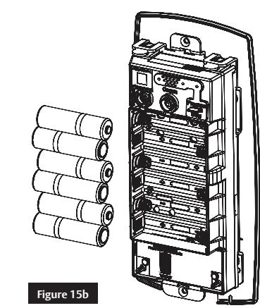
PWI (WiFi)
- 1. Once controller is securely in place, place (6) "AA" alkaline batteries in the compartment, being careful to align polarity properly. (Figure 15b)
- 2. After batteries are installed, there is a slight delay; LED will flash and the lock motor will cycle.

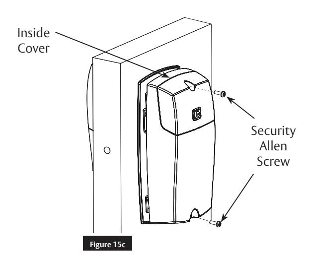
f Inside Cover Installation
- 1. Install cover by hooking top edge on inside mounting plate.
- 2. Carefully press bottom of cover toward door without pinching wires.
- 3. Secure the cover with the security allen wrench.


11 Operational Check

a Inside Cover Installation
Important: Be sure to test functions prior to closing door.
In all cases, perform the following checks:
- 1. Ensure that inside lever retracts latch.
- For units with cylinders, the following checks apply:
Note: Insert key into cylinder and rotate:
- a. There should be no friction against lock case or any other obstructions. If friction or binding occurs, re-adjust cylinder to eliminate issues.
- b. The key should retract the latch and the key should rotate freely.
- c. The key should extend and retract the deadbolt.
- For units without a keypad, add card using LCT software* and test.
- For units with a keypad, add pin and card using LCT software* and test.
-
2. LED signaling:
- a. After using a valid credential, a green flash followed by three fast amber flashes indicates a low power condition.
- b. Check the input voltage.
- c. If the input voltage is low, disconnect the lock from the power source and check the power source voltage. If the power source voltage is correct, inspect the lock wiring for a possible short.
- d. If the lock loses power, it will flash rapid blue for approximately one minute. Note: Lock will default to programmed fail safe or fail secure and will no longer be functional.
- 3. When you have completed the tests, close the door, ensuring latchbolt fully extends into strike plate without binding.
*Refer to Network and Lock Configuration Tool user manual (WFMN1) for information on how to configure and program locks.