Corbin Russwin A6, N6, and PR6 Lever Trim for ED8000 Series Wide Stile Installation Instructions_FM554
Open the original PDF document
View PDFInstallation Instructions

A6, N6 and PR6 Series Lever Trim
For use with ED8000 Series
Pushbar Exit Device

This product can expose you to lead which is known to the state of California to cause cancer and birth defects or other reproductive harm. For more information go to www.P65warnings.ca.gov.
Pushbar Exit Device
Installation Instructions

| TOC | Table of Contents | |
|---|---|---|
| 1 | Pre-Installation 2 | |
| a | Determine Hand of Door 2 | |
| b | Mark Centerline 3 | |
| c | Prepare Door 3 | |
| d | Prepare Trim 4 | |
| 2 | Installation 4 | |
| a | Install Trim 4 | |
| b | Remove and Reinstall Standard Cylinder 5 | |
| c | Interchangeable Core Locksets 6 | |
| 1 | Pre-Installation | |
| a | Determine Hand of Door |
Important:
- Failure to follow these instructions could affect operation of this product and void warranty.
- Exit devices must be securely fastened to properly reinforced doors with fasteners which will not loosen or pull out. Add reinforcement when necessary.
- • Before installing, be sure exit device is proper hand for door. (Figure 1)

Pushbar Exit Device
Installation Instructions

1 Pre-Installation (continued)
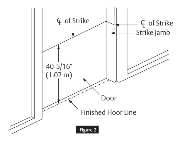
b Mark Centerline
To establish centerline of device, draw line across door and stop 40-5/16" (1.02 m) above finished floor unless doors have been pre-prepped. (Figure 2 )
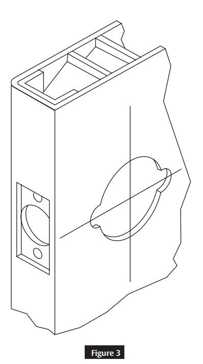
c Prepare Door
For doors with ANSI A1115.1 cylindrical lock cut-out:
• No further mounting or prep holes required. ( Figure 3 )
For non-Prepped doors:
• Use template furnished to spot and drill 2-1/8" (54 mm) hole through door.
For installation assistance contact Corbin Russwin
Installation Instructions

1 Pre-Installation (continued)
d Prepare Trim
Use break-off grooves (Figure 4 ) or cut trim tailpiece to extend 3/16" (5 mm) beyond device mounting surface, door face or shim surface. (Figure 5 )


2 Installation
a Install Trim
- 1. Insert trim into 2-1/8" (54 mm) hole and place device against inside surface of door. Be sure tailpiece of trim assembly engages into cross hole of cam in device head.
- 2. Insert two (2) #10-24 machine screws (packed with trim) into holes A and B of device head and thread into trim posts. ( Figure 6)
Note:
Trim posts are not included on trims for 1-3/8" (3 5mm) doors, so machine screws thread directly into plate.

Installation Instructions

2 Installation (continued)
b Remove and Reinstall Standard Cylinder
Remove Lever:
- 1. Insert key in cylinder and turn 45° clockwise.
- 2. Insert lever release tool into hole on side of lever and depress lever retainer.
- 3. While retainer is depressed, pull lever off.
Remove Cylinder:
- 1. Remove key.
- 2. Remove plastic filler.
- 3. Slide cylinder out.
Reinstall Cylinder:
- 1. Slide cylinder into lever.
- 2. Install plastic filler.
Reinstall Lever:
- 1. Insert key part way. Slide lever onto rollback as far as it will go, using key to guide cylinder into engagement.
- 2. Insert key fully and turn 45° clockwise.
- 3. Push lever the rest of the way onto rollback.
- 4. Remove key and pull lever to be sure it is properly retained on rollback.

For installation assistance contact Corbin Russwin
Pushbar Exit Device
Installation Instructions

2 Installation (continued)
c Interchangeable Core Locksets
If interchangeable core is already installed in lever:
• No further action is necessary.
For unprepped doors:
- 1. Locate recore driver packer and special CONTROL key.
- 2. Place spacer onto recore driver prongs and insert recore driver into holes in rear of core.
- 3. Insert CONTROL key and turn 15° clockwise to retract control lug.
- 4. Slide core with recore driver into lever.
- 5. As shown in Figure 8, core must be installed with keyed plug toward edge of door.
- 6. Turn CONTROL key counterclockwise and remove.
Notes:
- Control key has no further use in lockset installation and must be safeguarded for return to Security personnel when installation is complete.
- When assembling cylinders other than Corbin Russwin,keep blade of driver entering lever parallel to lever.

or in part without the express written permission of ASSA ABLOY Access and Egress Hardware Group, Inc. is prohibited.
Pushbar Exit Device
Installation Instructions


Corbin Russwin, Inc. 225 Episcopal Road Berlin, CT 06037 USA Phone: 800-543-3658 Fax: 800-447-6714 www.corbinrusswin.com